Note: Descriptions are shown in the official language in which they were submitted.
CA 02876759 2014-12-15
WO 2014/005171
PCT/AU2013/000584
-1 -
CEILING FAN
Introduction
This invention relates to a ceiling fan and more
particularly relates to a ceiling fan with retractable
blades.
Background of the Invention
The problem with many ceiling fans is that the
radially projecting blades become unsightly dust
collectors when the fan is not in use. Ceiling fans that
often incorporate light fittings and it has been proposed
to incorporate retractable blades that retract within the
confines of the light fitting when not in use and expand
radially outwardly when in use to operate as conventional
fan blades.
Problems with fans of this kind concern ensuring a
balanced configuration especially as the blades move
between the retracted and operative positions. A further
problem with fans of this kind is the limit on the length
of the blades to enable then to retract within the
confines of the light fitting. This usually requires the
blades to nest with the tip of one blade above the root of
the adjacent blade, thus leading to an unsightly slack of
blades. If the blades are made shorter to reduce the need
for overlapping then the blades lack the aerodynamics to
move sufficient air to operate efficiently as a fan.
It is these issues that have brought about the
present invention.
Summary of the invention
According to one aspect of the present invention
there is provided a fan blade comprising a mount
supporting a plurality of superimposed fan blade segments
arranged to slide relative to one another from a retracted
CA 02876759 2014-12-15
WO 2014/005171
PCT/AU2013/000584
-2 -
storage configuration to an extended operative
configuration.
According to another aspect of the present invention
there is provided a ceiling fan comprising an electric
motor adapted to drive a rotating plate that supports a
plurality of equally spaced fan blades that extend
radially of the plate, each fan blade comprising a root
and a tip joined by leading and trailing edges, the root
being adapted to be secured to the plate, wherein each
blade comprises a plurality of fan blade segments arranged
to slide telescopically one within the other whereby the
fan blade segments can be located substantially within the
periphery of the plate in a retracted configuration and
can extend radially outwardly in an operative
configuration.
Description of the Drawings
Embodiments of the present invention will now be
described by way of example only with reference to the
accompanying drawings in which:
Figures la, lb and lc are respectively plan, side and
perspective views of a fan in an expanded operative
configuration,
Figures 2a, 2b, and 2c are respectively plan, side
and perspective views of the fan in a retracted
inoperative configuration,
Figures 3a and 3b are respectively plan and side
elevational views of the fan in the retracted
configuration illustrating a drive assembly,
Figures 4a, 4b and 4c are respectively plan, side and
perspective views of the fan in the expanded operative
configuration with components omitted for clarity,
Figure 5 is a plan view of part of components for the
fan in the expanded configuration,
Figure 6 is a plan view of one blade assembly in the
expanded configuration,
CA 02876759 2014-12-15
WO 2014/005171
PCT/AU2013/000584
-3-
Figure 7 is a cross sectional view taken along the
lines A-A of Figure 6,
Figure 8 is a cross sectional view taken along the
lines B-B of Figure 6, and
Figure 9 is a cross sectional view taken along the
lines C-C of Figure 6.
Description of the Preferred Embodiments
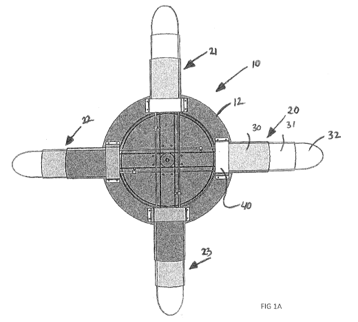
The ceiling fan 10 as illustrated in the accompanying
drawings comprises an electric motor 11 that is hung from
the ceiling. The electric motor 11 is coupled to a
circular plate 12 whereby the motor 11 rotates the plate
12 about a vertical axis. The plate 12 is adapted to
support four equally spaced fan blade assemblies 20, 21,
22, 23. Each blade assembly 20 to 23 comprises three fan
blade segments 30, 31, 32 that can slide relative to one
another from a retracted position (Figure 2) where the fan
blade segments are within the confines of the plate 12 to
an outward operative position (Figure 1) in which the fan
blade segments 30-32 project radially outwardly of the
plate 12 to facilitate movement of air as the plate 12 is
rotated by the electric motor 11. It is understood that
the electric motor 11 can be either on top of or below the
plate 12.
Each blade assembly 20- 23 is positioned on the
periphery of the plate 12 via a mount 40 that is secured
to the plate 12. As shown in Figure 2a the mounts 40 are
equally spaced around the periphery of the plate to be
diametrically opposed to one another.
In this embodiment the blade comprises three blade
segments, namely the first outer segment 30, an
intermediate segment 31 that is telescopically mounted
within the outer segment 30, and an inner blade tip 32
that is again telescopically mounted within the
intermediate section.
CA 02876759 2014-12-15
WO 2014/005171
PCT/AU2013/000584
-4 -
Each mount 40 comprises a pair of support legs 41, 42
having outwardly extending flanges 43, 44 that enable the
legs to be screwed to the surface of the plate 12. The
support legs 41, 42 support a bridging member 45 that
defines a slot 46 that accommodates a first outer blade
segment 30. The slot defines a passageway that allows the
blade segments 30 to be a smooth sliding fit within the
slot 46. The legs 41, 42 of the mount assembly are also
arranged so that the slot is on an incline of between 10
and 15 degrees (see Figure 2b). The angle on the slot
gives the blade, which is otherwise flat, an angle of
incidence to give the desired air movement when in the
extended and operative position.
The blade segments 30, 31, 32 all slide relative to
one another so that in the retracted position (Figure 2)
the tip 32 is wholly within the intermediate segment 31
which is wholly within the outer segment 30. In the
extended position shown in Figure 2 the tip 32 projects
radially outwardly of the intermediate segment 31 which is
in turn radially outwardly of the outer segment 30. The
telescopic arrangement of the three blade segments allows
the segments to slide outwardly and the force to urge this
outward movement is the centrifugal force generated by
rotation of the plate 12 by the electric motor 11.
Each diametrically opposed pair of blade assemblies
21, 22 or 23, 24 are interconnected by a chain 50 that
rotates about a sprocket 51 located on the underside of
each mount 40. The chain is also coupled to a centrally
located sprocket 52 that is in turn coupled to a coil
spring 53 located within a housing 54. The chain 50 is
attached to an elongate rod 60 via an adjustable linkage.
As shown in Figure 6 the rod 60 extends parallel to
the chain 50 and is coupled to an inner end of the outer
CA 02876759 2014-12-15
WO 2014/005171
PCT/AU2013/000584
-5 -
blade segment 32. Movement of the chain 50 pills the rod
60 radially inwards to pull the outer blade segment 32
into the intermediate segment 31 until the inner end of
the blade segment 32 abuts stop 63 on the inner end of the
intermediate segment 31. Further movement of the rod 60
causes inward displacement of the intermediate segment 31
until it engages stops 64 on the inner end of the first
blade segment 30. Al these segments 30, 31, 32 are then
pulled by the rod 60 under the mount 40 to assume the
fully retracted position shown in Figure 2.
As the centrifugal force of the fan 10 forces the
blade 30-32 segments outwardly the movement of the
segments causes rotation of the sprocket 51 under the
mount 40 to drive the chain 50 to in turn rotate the
central sprocket 52 against the spring 53. As the fan 10
slows down the coil spring 53 urges the central sprocket
52 to rotate the chain 50 and pull back the fan segments
30-32 to the retracted position. In this manner, the
sprocket and chain drive not only controls the outward
movement of the fan segments but through the spring 53
brings the segments back into the retracted position when
not in use. To avoid collision of the chains 50 two
central sprockets 52 are provided in different vertical
planes with the upper sprocket driving the fan blade
assemblies 20 and 21 and the lower sprocket driving the
other pair of fan blade assemblies 22 and 23.
The fan blade segments 30-32 are moulded in plastics
to define leading and trailing edges. The blade segments
30-32 are substantially flat and the tip segment 32 has a
curved end.
The fan described above has a number of advantages
over conventional fans with retractable blades. Because
the blades do not pivot from the operative to the
retracted positions there is no danger of collision
CA 02876759 2014-12-15
WO 2014/005171
PCT/AU2013/000584
-6 -
between the blades during the retraction process.
Furthermore, the fact that the blade segments expand
radially or in a longitudinal sense means that the blades
can be designed to have increased length to thereby
increase the airflow. Furthermore, the telescopic
location of the blade segments allows the fan to assume a
compact and comparatively thin configuration in the
retracted position which makes the fan, especially when it
incorporates a light fitting, much more attractive in the
retracted position than is the case with other fans with
retractable blades where the blades form an unsightly nest
above the light fitting.
In the claims which follow and in the preceding
description of the invention, except where the context
requires otherwise due to express language or necessary
implication, the word "comprise" or variations such as
"comprises" or "comprising" is used in an inclusive sense,
i.e. to specify the presence of the stated features but
not to preclude the presence or addition of further
features in various embodiments of the invention.