Note: Descriptions are shown in the official language in which they were submitted.
1
Control means of central flow system and central flow system
TECHNICAL FIELD
The present invention relates to an arrangement for automatic air treatment.
BACKGROUND ART
In surgery rooms of today, there is often a suction outlet. The suction outlet
is intended to
ventilate for example anesthetic gas leaking around the anesthesia mask or
anesthesia as the
patient exhales. These suction outlets are often linked to an extraction
system consisting of a
central suction unit, which through a piping system is connected to several
sockets in different
surgery rooms.
A problem associated with prior art central vacuum systems is that
installation of them
requires manual adjustment. Central vacuum systems also require manual
adjustment during
operation. This manual adjustment is sometimes done by means of a control knob
in the
surgery room.
The known central vacuum systems may have difficulties adjusting suction flow
to varying
loads on the central vacuum system, because of problematic pipe installation.
If for example
many surgeries are ongoing in parallel and multiple suction outlets are used
simultaneously,
the flow may vary at the individual suction outlets. Readjustment may need to
be made on the
control panels if you change or replace the patient systems connected to the
suction outlets
so that the flow resistance changes. Usually, negative pressure needs to be
set extremely high
in the systems, which draws energy unnecessarily.
There is also central vacuum systems that are controlled by valves, which are
controlled based
on the amount of harmful gases in the air. In these systems, there is a
function of delay in that
harmful gases are emitted before they are captured by the central vacuum
system. Moreover,
usually the flow is not measured, but only the vacuum level and thus, the
flows cannot be set
for the various suction outlets coupled to the central vacuum system.
CA 2876815 2019-12-17
2
There is therefore a need for an improved central vacuum system that solves or
at least
mitigates at least one of the above problems.
SUMMARY OF THE INVENTION
An object of the present invention is to reduce or solve at least one of the
above problems.
A first embodiment of the present invention provides a control means for a
channel
connectable to a central flow system configured to create an underpressure or
overpressure in
said channel. The control means is configured to increase or decrease the flow
resistance in
said channel. The control means is configured to reduce flow resistance when
the flow in said
channel drops below a preset flow and to increase the flow resistance when the
flow in said
channel rises above said preset flow.
An object of the present invention is thus achieved by a control means
connectable to a
channel in a central flow system configured to create an underpressure or
overpressure in said
channel. Since the control means is configured to reduce flow resistance when
the flow in said
channel falls below a preset flow and to increase the flow resistance when the
flow in said
passage exceeds said preset flow, the preset flow can be maintained in such a
suction outlet
coupled to the channel despite varying loads on the suction outlets and/or the
central flow
system.
An advantage of the present invention is that the preset flow for instance in
a suction outlet in
a central flow system can be maintained despite varying loads on the suction
outlets and/or
the central flow system.
A further advantage of the present invention is that the installation of a
central flow system is
substantially simplified when individual adjustment of separate suction
outlets in a central
flow system is not necessary. The control means automatically sets the correct
flow
resistance.
Further advantages and features of embodiments of the present invention will
be apparent in
the following detailed description.
CA 2876815 2019-12-17
3
BRIEF DESCRIPTION OF THE DRAWINGS
Figure 1 shows a schematic block diagram of a central flow system according to
prior art.
Figure 2 shows a schematic block diagram of an example of a control means
according to the
present invention.
Figure 3 shows a schematic block diagram of an example of a control means
according to the
present invention.
Figure 4 shows a schematic block diagram of an example of a control means
according to the
present invention.
Figure 5 shows a schematic block diagram of an example of a control means
according to the
present invention.
Figure 6 shows a schematic block diagram of a central flow system according to
one
embodiment of the present invention.
Figure 7 shows a schematic block diagram of a central flow system according to
one
embodiment of the present invention.
DETAILED DESCRIPTION
Figure 1 shows a central flow system 10 according to prior art. The central
flow system 10 can
e.g. be installed in a hospital in order to provide the surgery rooms in a
hospital with a suction
outlet to ventilate anesthetic gases exhaled by a patient. The central flow
system 10 includes a
central fan 20 configured to create a vacuum in at least a channel 60
connected to said central
fan 20. Figure 1 illustrates only one channel 60 connected to said central fan
20, but there are
usually several channels 60 connected to the central fan 20. In the channel
60, a control
means 30 is configured to increase or reduce the flow resistance of said
channel 60. The flow
resistance of the control means 30 is controlled through a control panel 80
connected to said
control means 30. On the control panel 80, the flow resistance of the control
means 30 may
be increased or decreased. A flow sensor 90 is also connected to the control
means 30 or to
the channel 60. The flow sensor shows the flow in the channel 60. By reading
the flow of the
CA 2876815 2019-12-17
4
flow sensor 90, an operator of the central flow system 10 can control the flow
in the channel
60 on the control panel 80.
Figure 2 shows an example of an embodiment of a control means 35 according to
the present
invention. The control means 35 can be connected in a channel 60 connected to
a central flow
system 10 configured to create an underpressure or overpressure in said
channel 60. The
control means 3 according to the present invention is configured to increase
or reduce the
flow resistance of said channel 60 automatically, without the need for an
operator to manually
adjust the flow resistance of the control means 35. The control means 35 of
the present
invention is configured to reduce the flow resistance when the flow in said
channel 60 falls
below a predetermined flow rate and to increase the flow resistance when the
flow in said
channel 60 rises above said predetermined flow rate. In an exemplary
embodiment of a
control means 35 according to the present invention, the flow resistance is
controlled with a
valve (not shown) that is automatically opened or closed to change the flow
resistance. The
preset value can be received from for instance a control knob or be stored in
the control
means 35. The control means may in one embodiment comprise means (not shown)
to
measure the flow through the control means 35. In another embodiment, the
control means is
configured to receive a signal indicating the flow through the control means
35.
In a further example of an embodiment of a control means 35, a processing
means (not
shown) is provided in the control means 35. The processing means can for
example be a
microprocessor. The processing means is configured to receive the preset flow
and a signal
indicative of the flow through the control means 35. The processing means is
configured to
send a signal to e.g. a valve in the control means so that the valve reduces
flow resistance
when the flow in the channel 60 falls below a preset flow and to increase the
flow resistance
when the flow in the channel 60 rises above said preset flow.
Figure 3 shows a further example of an embodiment of a control means 35
according to the
present invention, the control means 35 is further configured to send a first
signal 36 to
increase the pressure in case the flow does not reach said preset flow despite
that said control
means 35 is fully open in the event that that control means 35 is configured
to regulate flow in
a pressure relief systems and to reduce the pressure in case the flow does not
reach said
.. preset flow despite that said control means 351s fully open in the event
said control means 35
CA 2876815 2019-12-17
5
is configured to regulate the flow in a negative pressure system. The signal
36 may for
example by sent to a central fan in the system in which the control means 35
is used.
Figure 4 shows a further example of an embodiment of a control means 35
according to the
present invention. In this exemplary embodiment, the control means 35 is
further configured
' 5 to receive a signal 37 indicative of the flow in said channel 60,
said signal being a pressure
change across a restriction in the said channel 60. In another example of an
embodiment of a
control means 35 according to the present invention, the signal 37 is a flow
in the channel 60.
In a further example of an embodiment of a control means 35 according to the
present
invention, the control means 35 is further configured to send a second signal
indicating the
flow in said channel 60. The signal may for example be received by a flow
viewer that shows
the flow in the channel 60. The flow viewer may for example be present in a
surgery room to
which the control means 35 controls the flow.
Figure 5 shows a further example of an embodiment of a control means 35 of the
present
invention. In this embodiment, the control means 35 is further configured to
receive a signal
38 indicative of said preset flow in said channel 60. The signal may for
instance be sent from a
control panel 39 in the surgery room to which the channel 60 is connected. The
default flow
can also be stored in the control means 35.
In an exemplary embodiment of a control means 35 according to the present
invention, the
control means 35 is configured to control the flow in a negative pressure
system.
In another example of an embodiment of a control means 35 according to the
present
invention, the control means 35 is configured to control the flow in an
overpressure system.
In another example of an embodiment of a control means 35, said control means
35 includes a
motor operated valve. In an exemplary embodiment of a control means 35
according to the
present invention said motor operated valve a diaphragm valve or other valve
configured to
cause minimal noise.
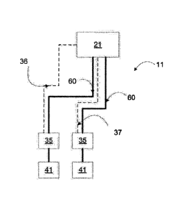
Figure 6 shows another aspect of the present invention, which is a central
flow system 11
comprising at least one control means 35 according to anyone of the previously
described
embodiments. The central flow system 11 may for example be installed in a
hospital in order
to provide surgery rooms in the hospital with a suction outlet 41 to ventilate
for instance
CA 2876815 2019-12-17
6
anesthetic gases exhaled by a patient. The central flow system 11 includes a
central fan 21
configured to generate a negative pressure or positive pressure in the at
least one channel 60
connected to said central fan 21. Figure 6 illustrates only one channel 60
connected to said
central fan 21, but there are usually several channels 60 connected to the
central fan 21.
Figure 6 illustrates a central fan 21, but the central flow system 11 may also
include several
central fans.
In another exemplary embodiment of the central flow system 11 according to the
present
invention, the central fan 21 is further configured to receive a first signal
36 and increase the
pressure in case the central fan 21 is configured to create an excess pressure
and reduce the
pressure in the case the central fan 21 is configured to create a vacuum. The
signal 36 may, in
one embodiment, be transmitted from the one or more control means 35 of the
central flow
system 11.
In another exemplary embodiment of the central flow system 11 according to the
present
invention, the central fan 21 is a subchannel blower or other suction device
configured to
cause minimal noise.
In yet another exemplary embodiment of the central flow system 11 according to
the present
invention, the central fan 21 further configured to establish the increase or
decrease in
pressure during a certain period of time and then return to a normal state.
In all embodiments of the central flow system 11 according to the present
invention, there
may be one or more central fans 21. The central fans 21 may be either
connected in series or
connected in parallel.
CA 2876815 2019-12-17