Note: Descriptions are shown in the official language in which they were submitted.
CA 02877020 2015-01-12
Apparatus, system and method for separating sand and other solids from
oil and other fluids
Field of the Invention
This invention relates generally to the field of sand filters and methods of
separating fracturing sand from the desired hydrocarbons from wells.
Background of the Invention
Gas resources such as shale are accessed using a process called hydraulic
fracturing. Fracturing, or `Tracking," process begins with the drilling of a
well into
a rock formation This technique further involves injecting a mixture of water,
sand and a small amount of other additives (blend of chemicals) into a well.
These fluids typically consist of about 90 percent water and 9.5 percent sand.
Many of the ingredients in the remaining 0.5 percent of the mixture have
common consumer applications in household products, detergents and
cosmetics. These chemicals are used to reduce friction, prevent bacteria
growth
and protect the rock formation, making the hydraulic fracturing safer and more
efficient.
The pressurized hydraulic fluid acts as a propping agent or proppant and
creates
hairline cracks in the shale and these cracks, held open by the sand
particles,
allow the gas to flow up through the wellbore to the surface. So, fracture
sand is
commonly introduced into the reservoir in an effort to create "conductive
channels" from the reservoir rock into the wellbore, thereby allowing the
1
CA 02877020 2015-01-12
hydrocarbons a much easier flow path into the tubing and up to the surface of
the
well.
Hydraulic fracturing is not new. It was first used in conventional oil and gas
extraction in the late 1940s in North America. Since then, more than one
million
wells around the world have been drilled using hydraulic fracturing. In
Alberta, it
has been used for more than 60 years to safely and reliably fracture over
167,000
wells. What is new, however, is the use of multiple technologies in
conjunction
with one another to make accessing unconventional gas more feasible. By
combining hydraulic fracturing with horizontal drilling, operators can safely
produce affordable, reliable quantities of natural gas from shale and other
unconventional sources.
The well equipment which is used to produce oil from a well typically includes
components that are designed to separate the unwanted substances from the oil.
For instance, a sand separator is commonly provided at the surface of the well
to
remove the sand that may be present as a result of fracking.
Conventional sand separation systems primarily rely on gravity to separate the
sand from the fluids that are produced from a well. Typically, fluid is
introduced
into the central portion of a large, vertically oriented chamber through a
pipe
that is referred to as a stinger. The fluid flows slowly upward, typically
through
one or more baffles, to an outlet at the top of the chamber. The chamber has a
large diameter so that the linear speed of the fluid flowing through the
chamber
will be minimized. This allows the sand to settle out of the fluid and fall to
the
bottom of the chamber, where it can be accumulated and removed.
2
CA 02877020 2015-01-12
There are various problems with the use of conventional sand separators to
remove sand from oil or other fluids. For example, as noted above, the chamber
of the apparatus needs to be large in order to minimize the speed of the fluid
so
that the sand can settle out. The large size of the apparatus can make it
difficult
to transport and install. Additionally, because of material cost, the sheer
size of
apparatus makes it more expensive.
Another problem is that it is difficult to accommodate the different operating
conditions and fluid characteristics that may exist in different wells. For
instance,
one well may have a higher flow rate than another, so the settling of the sand
out
of the faster-flowing fluid may be less effective. Likewise, higher viscosity
or
lower temperature of the fluid may reduce settling in a conventional sand
separator. Addressing these problems may require that an entirely different
sand
separator be used.
Overall, natural or manmade particulates can cause a multitude of producing
problems for oil and gas operators. For example, in flowing wells abrasive
particulates can "wash through" metals in piping creating leaks and
potentially
hazardous conditions. Particulates can also fill-up and stop-up surface flow
lines,
vessels, and tanks. In reservoirs whereby some type of artificial lift is
required
such as rod pumping, electric submersible pumps, progressive cavity, and other
methods, production of particulates can reduce of the life of the down-hole
assembly and increase maintenance cost.
It is an object of the present invention to obviate or mitigate the above
disadvantages.
3
CA 02877020 2015-01-12
Summary of the Invention
It is an object of the present invention to provide an apparatus, system and
method for separating sand and other solids from oil and other fluids that may
be
produced from a well, wherein this apparatus, system and method solve one or
more of the problems discussed above.
It is an object of the present invention to provide an apparatus comprising
one or
more screens which is use eliminates sand and/or fluid slugs from blocking at
a
screen by placing at least the screen in an elevated secondary chamber,
configured to prevent sand, fluid slugs and the like from accumulating around
the screen.
It is an object of the present invention to provide an apparatus comprising
one or
more screens which eliminates sand carryover. Current used apparatus allow
sand to carryover through the system, wherein system fills with sand and/or
fluid slugs and wherein sand is therein carried past the sand catcher.
It is an object of the present invention to provide an apparatus, system and
method wherein the combined principles of "velocity knockout", at a first step
of
processing and selective screening, at second and third steps (wherein such
screening at a second step provides filtration of sand particles within
specific
particle size), reduces the restriction of fluid flow caused by screen
blockage.
4
CA 02877020 2015-01-12
It is an object of the present invention to provide an apparatus, system and
method which reduces and/or eliminates screen damage with a hydrate breaker
between at least a first step of processing and a third step of processing.
It is an object of the present invention to provide an apparatus, system and
method which eliminates exposure of operators to process
fluids/particulates/other by-products ("waste") during a hydraulic fracking,
flowback and related production whereby a blowdown process uses well
pressure to transfer waste to a storage vessel, either via a manual or an
automated trigger.
The present disclosure specifically provides a series of method/process steps
(an
alternative systems and apparatus for use therewith) for separating sand and
other solids from oil and/or other fluids therein generating cleaned fluids.
Applications for use are across a wide variety of industries, such industries
not
being limited to the oil and gas industry, mining, pulp and paper,
semiconductor,
food and beverage, chemical plating, as well as municipal waste water
treatment,
electric power generation, environmental remediation, and the generation of
clean water for human, animal and agricultural uses.
The present invention provides a sand filtering apparatus for separating
solids
from a fluid comprising:
a) a horizontally disposed gravity knock-out tube;
b) an inlet at a first end of the tube for introducing untreated fluid;
said tube
being of a size and configuration such that, in operation, gravitational force
on
particles of the solid substantially exceeds any drag created by flow of said
fluid,
CA 02877020 2015-01-12
thereby to induce gravity settling of at least a portion of the solid at a
bottom of
the tube ("settled solids"), said settled solids, in situ, serving to
increased
differential pressure from the inlet to an outlet;
c) the outlet, disposed at a second end of the tube, opposing the first end
and
in fluid communication with at least one of i) a vertically oriented tubular
screen
chamber and ii) a horizontally oriented tubular screen chamber, wherein
vertically oriented tubular screen chamber and horizontally oriented tubular
screen chamber (together, the "tubular screen chambers") are elevated relative
to the horizontally disposed gravity knock-out tube to prevent/reduce solids
from accumulating around the tubular screen chambers;
d) perforated plate for secondary filtering disposed between outlet and
vertically oriented tubular screen chamber or horizontally oriented tubular
screen chamber, said perforated plate
wherein vertically oriented tubular screen chamber and horizontally oriented
tubular screen chamber comprise a wire wrapped slotted screen configured to
filter out fine particulates and wherein wire wrapped slotted screen is housed
within a removable cartridge.
The present invention further provides a method for separating sand or other
solids from oil or other fluids that are produced from a well, the method
comprising:
a) introducing a fluid containing solids into a horizontally disposed
gravity
knock-out tube, wherein the fluid is introduced into the horizontally disposed
gravity knock-out tube rate and direction such that a gravitational force on
particles of the solid substantially exceeds any drag created by flow of said
fluid,
6
CA 02877020 2015-01-12
thereby to induce gravity settling of at least a portion of the solid at a
bottom of
the tube ("settled solids"), said settled solids, in situ, serving to
increased
differential pressure from the inlet to an outlet and therein forming a
primary
treated fluid;
b) passing said primary treated fluid to a vertically oriented tubular
screen
chamber via a perforated plate, wherein vertically oriented tubular screen
chamber is elevated relative to the horizontally disposed gravity knock-out
tube
to prevent/reduce solids from accumulating around the vertically orientated
tubular screen chamber, wherein vertically oriented tubular screen chamber
comprises a wire wrapped slotted screen configured to filter out fine
particulates
and wherein wire wrapped slotted screen is housed within a removable
cartridge.
The present invention further provides a method for separating sand or other
solids from oil or other fluids that are produced from a well, the method
comprising:
a) introducing a fluid containing solids into a horizontally disposed
gravity
knock-out tube, wherein the fluid is introduced into the horizontally disposed
gravity knock-out tube rate and direction such that a gravitational force on
particles of the solid substantially exceeds any drag created by flow of said
fluid,
thereby to induce gravity settling of at least a portion of the solid at a
bottom of
the tube ("settled solids"), said settled solids, in situ, serving to
increased
differential pressure from the inlet to an outlet and therein forming a
primary
treated fluid; and
7
CA 02877020 2015-01-12
b)
passing said primary treated fluid to a horizontally oriented tubular
screen chamber oriented tubular screen chamber via a perforated plate, wherein
horizontally oriented tubular screen chamber is elevated relative to the
horizontally disposed gravity knock-out tube to prevent/reduce solids from
accumulating around the horizontally orientated tubular screen chamber,
wherein horizontally oriented tubular screen chamber comprises a wire
wrapped slotted screen configured to filter out fine particulates and wherein
wire wrapped slotted screen is housed within a removable cartridge.
Using the method, apparatus and system of the invention, there is a reduction
in
the frequency for on-site personnel at a well site as well as a savings of
thousands of dollars per day on worksites. Furthermore the method, apparatus
and system of the invention reduces the frequency of Vac-Truck trips to clean
out
the filters or remove other waste by-products. This can lead to tens of
thousands
in savings per month for each well.
These and other advantages will become apparent throughout this specification.
Brief Description of the Drawings
Figure 1 is a perspective view of a horizontal/vertical sand filter apparatus;
Figure 2 is a side plan view of a horizontal/vertical sand filter apparatus;
Figure 3 is a side view of horizontal/vertical sand filter apparatus;
Figure 4 is side view horizontal/vertical sand filter apparatus illustrating
three
stages/steps of filtration;
8
CA 02877020 2015-01-12
Figure 5 is a side plan view of the area in which the initial section or step
one is
performed;
Figure 6 is a side view of a vertical screen/wire-wrapped slotted screen and
gas
flow diagram;
Figure 7 is a side plan view of a horizontal/horizontal sand filter apparatus;
Figure 8 is a perspective view of the horizontal/horizontal sand filter
apparatus
shown in Figure 7;
Figure 9 is a side plan view of parts of a horizontal/horizontal sand filter
apparatus;
Figure 10 is a side plan view of a horizontal/horizontal sand filter apparatus
illustrating three stages/steps of filtration;
Figure 11 is a side plan view of the "primary vessel" (area in which the
initial
section or step one is performed) namely sand accumulation and gas flow;
Figure 12 is a side plan view of a sand filter/gas flow in horizontal screen
chamber (comprising wire-wrapped slotted screen);
Figure 13 is a perspective view of step 3¨showing vertically oriented tubular
screen chamber and horizontally oriented tubular screen chamber comprise a
wire wrapped slotted screen configured to filter out fine particulates and
wherein wire wrapped slotted screen is housed within a removable cartridge
wherein Figure 13 illustrates removable cartridge in place;
Figure 14 is a perspective view of step 3¨showing vertically oriented tubular
screen chamber and horizontally oriented tubular screen chamber comprise a
9
CA 02877020 2016-03-23
wire wrapped slotted screen configured to filter out fine particulates and
wherein wire wrapped
slotted screen is housed within a removable cartridge, wherein Figure 14
illustrates removable
cartridge with screen removed;
Figure 15 is a side view of vertically oriented tubular screen chamber;
Figure 16 is a further embodiment of vertically oriented tubular screen
chamber;
Figure 17 is a side plan view of the orientation and operation of the blowdown
valves; and
Figure 18 is a graph showing sand filter flow rates.
Figure 19 is a diagram used in the Example Flow Rate Calculation showing the
gas and frac sand from
the vessel with the frac sand stopped by the wrapped screen.
The figures depict embodiments of the present invention for purposes of
illustration only. One skilled
in the art will readily recognize from the following description that
alternative embodiments of the
structures and methods illustrated herein may be employed without departing
from the principles of
the invention described herein.
Detailed Description of the Preferred Embodiments
A detailed description of one or more embodiments of the invention is provided
below along with
accompanying figures that illustrate the principles of the invention. The
invention is described in
connection with such embodiments, but the invention is not limited to any
embodiment. The scope of
the invention is limited only by the claims and the invention encompasses
numerous alternatives,
modifications and equivalents. Numerous specific details are set forth in the
following description in
order to provide a thorough understanding of the
17478338.1
CA 02877020 2016-01-07
invention. These details are provided for the purpose of example and the
invention may be practiced according to the claims without some or all of
these
specific details. For the purpose of clarity, technical material that is known
in the
technical fields related to the invention has not been described in detail so
that
the invention is not unnecessarily obscured.
I. Terms
The term "product" means any machine, manufacture and/or composition of
matter, unless expressly specified otherwise.
The term "method" means any process, method or the like, (and vice versa)
unless expressly specified otherwise.
Each process (whether called a method or otherwise) inherently includes one or
more steps, and therefore all references to a "step" or "steps" of a process
have
an inherent antecedent basis in the mere recitation of the term "process" or a
like
term. Accordingly, any reference in a claim to a "step" or "steps" of a
process has
sufficient antecedent basis.
11
CA 02877020 2016-01-07
The term "invention" and the like mean "the one or more inventions disclosed
in
this application", unless expressly specified otherwise.
The terms "an aspect", "an embodiment", "embodiment", "embodiments", "the
embodiment", "the embodiments", "one or more embodiments", "some
embodiments", "certain embodiments", "one embodiment", "another
embodiment" and the like mean "one or more (but not all) embodiments of the
disclosed invention(s)", unless expressly specified otherwise.
The term "variation" of an invention means an embodiment of the invention,
unless expressly specified otherwise.
A reference to "another embodiment" or "another aspect" in describing an
embodiment does not imply that the referenced embodiment is mutually
exclusive with another embodiment (e.g., an embodiment described before the
referenced embodiment), unless expressly specified otherwise.
The terms "including", "comprising" and variations thereof mean "including but
not limited to", unless expressly specified otherwise.
The terms "a", "an" and "the" mean "one or more", unless expressly specified
otherwise.
The term "plurality" means "two or more", unless expressly specified
otherwise.
The term "herein" means "in the present application
12
CA 02877020 2016-01-07
, unless expressly specified otherwise.
The phrase "at least one of', when such phrase modifies a plurality of things
(such as an enumerated list of things) means any combination of one or more of
those things, unless expressly specified otherwise. For example, the phrase
"at
least one of a widget, a car and a wheel" means either (i) a widget, (ii) a
car, (iii) a
wheel, (iv) a widget and a car, (v) a widget and a wheel, (vi) a car and a
wheel, or
(vii) a widget, a car and a wheel. The phrase "at least one of', when such
phrase
modifies a plurality of things does not mean "one of each of' the plurality of
things.
It should be noted that several of the terms used in this disclosure are
preceded
by the descriptors "generally" or "substantially". These descriptors are used
to
indicate that a term which is preceded by one of these descriptors is intended
to
be construed broadly. For instance, a cylinder is a well-defined mathematical
construct and it does not technically encompass conic sections. Because the
separation chamber described above may be cylindrical, or may have a slightly
tapered wall, the chamber is described as "generally cylindrical". Similarly,
the
fluid flow through the separation chamber is described as "generally
circular",
which should be construed to include helical and conical (helical with a
decreasing diameter) flow paths. This interpretation of the terms used herein
will be easily understood by a person of ordinary skill in the art of the
invention.
While the foregoing disclosure primarily discusses apparatus, systems and
methods for removing sand from oil, (and specifically in the fracking process)
it
is to be understood they can be more broadly applied to the removal of other
solids from various types of fluids. Consequently, as used above, "sand"
should be
13
CA 02877020 2015-01-12
construed to both sand and other types of solids that might be found in fluids
produced from a well. Similarly, "fluids" should be construed to include oil,
water, gas, and other fluids that might be produced from a well.
As used herein, the term "frac sand" is sand used as a proppant to keep
underground fractures or fissures (created through the process of hydraulic
fracturing) propped open. Proppant sand can be natural sand or it can be resin
coated - but usually only the naturally occurring (uncoated) type is called
frac
sand.
As used herein, the term "fracking" or hydraulic fracturing, is the process of
using
a high pressure fluids to create fissures in relatively impermeable rock
(formations in which the pores that contain hydrocarbons are not very well
interconnected) to enable gas or oil to flow out of the well. Chemicals are
pumped into the ground as a result of fracking, and it is often necessary to
drill
through drinking water aquifers.
As used herein, the term "hydraulic fracturing" is the process of using high
pressure fluids to create fractures in a very tight formation that otherwise
would
not let hydrocarbons to freely pass into a well. The fractures increase the
permeability of the formation
As used herein, the term "hydrocarbon" is a chemical compound comprised of
only carbon and hydrogen. The fuels such as a natural gas and oil that energy
14
CA 02877020 2015-01-12
producers take out of the ground are often referred to as hydrocarbons. Gas
and
oil, as taken out of the ground, are each actually comprised of a mixture of
different types of hydrocarbons, plus impurities. Hydrocarbons generally can
be
burned to produce heat
Numerical terms such as "one", "two", etc. when used as cardinal numbers to
indicate quantity of something (e.g., one widget, two widgets), mean the
quantity
indicated by that numerical term, but do not mean at least the quantity
indicated
by that numerical term. For example, the phrase "one widget" does not mean "at
least one widget", and therefore the phrase "one widget" does not cover, e.g.,
two
widgets.
The phrase "based on" does not mean "based only on", unless expressly
specified
otherwise. In other words, the phrase "based on" describes both "based only
on"
and "based at least on". The phrase "based at least on" is equivalent to the
phrase
"based at least in part on".
The term "represent" and like terms are not exclusive, unless expressly
specified
otherwise. For example, the term "represents" do not mean "represents only",
unless expressly specified otherwise. In other words, the phrase "the data
represents a credit card number" describes both "the data represents only a
credit card number" and "the data represents a credit card number and the data
also represents something else".
The term "whereby" is used herein only to precede a clause or other set of
words
that express only the intended result, objective or consequence of something
that
CA 02877020 2015-01-12
is previously and explicitly recited. Thus, when the term "whereby" is used in
a
claim, the clause or other words that the term "whereby" modifies do not
establish specific further limitations of the claim or otherwise restricts the
meaning or scope of the claim.
The term "e.g." and like terms mean "for example", and thus does not limit the
term or phrase it explains. For example, in a sentence "the computer sends
data
(e.g., instructions, a data structure) over the Internet", the term "e.g."
explains
that "instructions" are an example of "data" that the computer may send over
the
Internet, and also explains that "a data structure" is an example of "data"
that the
computer may send over the Internet. However, both "instructions" and "a data
structure" are merely examples of "data", and other things besides
"instructions"
and "a data structure" can be "data".
The term "respective" and like terms mean "taken individually". Thus if two or
more things have "respective" characteristics, then each such thing has its
own
characteristic, and these characteristics can be different from each other but
need not be. For example, the phrase "each of two machines has a respective
function" means that the first such machine has a function and the second such
machine has a function as well. The function of the first machine may or may
not
be the same as the function of the second machine.
The term "i.e." and like terms mean "that is", and thus limits the term or
phrase it
explains. For example, in the sentence "the computer sends data (i.e.,
instructions) over the Internet", the term "i.e." explains that "instructions"
are
the "data" that the computer sends over the Internet.
16
CA 02877020 2016-01-07
. ,
Any given numerical range shall include whole and fractions of numbers within
the range. For example, the range "1 to 10" shall be interpreted to
specifically
include whole numbers between 1 and 10 (e.g., 1, 2, 3, 4, ... 9) and non-whole
numbers (e.g. 1.1, 1.2,... 1.9).
Where two or more terms or phrases are synonymous (e.g., because of an
explicit
statement that the terms or phrases are synonymous), instances of one such
term/phrase does not mean instances of another such term/phrase must have a
different meaning. For example, where a statement renders the meaning of
"including" to be synonymous with "including but not limited to", the mere
usage
of the phrase "including but not limited to" does not mean that the term
"including" means something other than "including but not limited to".
Numerous embodiments are described in the present application, and are
presented for illustrative purposes only. The described embodiments are not,
and are not intended to be, limiting in any sense. The presently disclosed
17
CA 02877020 2015-01-12
invention(s) are widely applicable to numerous embodiments, as is readily
apparent from the disclosure. One of ordinary skill in the art will recognize
that
the disclosed invention(s) may be practiced with various modifications and
alterations, such as structural and logical modifications. Although particular
features of the disclosed invention(s) may be described with reference to one
or
more particular embodiments and/or drawings, it should be understood that
such features are not limited to usage in the one or more particular
embodiments
or drawings with reference to which they are described, unless expressly
specified otherwise.
No embodiment of method steps or product elements described in the present
application constitutes the invention claimed herein, or is essential to the
invention claimed herein, or is coextensive with the invention claimed herein,
except where it is either expressly stated to be so in this specification or
expressly recited in a claim.
H Overview
The present invention provides an apparatus, system and method for separating
sand and other solids from oil and other fluids that may be produced from a
well,
wherein this apparatus, system and method solve one or more of the problems
discussed above.
The apparatus, system and method breaks down the sand filtering into three
stages or steps of processing 1) gravity knock-out processing in horizontally
disposed gravity knock-out tube; 2) tubular screen chamber filtering, wherein
tubular screen chamber (whether horizontal or vertical) is elevated relative
to
the horizontally disposed gravity knock-out tube to prevent/reduce solids from
18
CA 02877020 2015-01-12
accumulating around the tubular screen chambers; and 3) secondary filtering
through a perforated plate (disposed between outlet and tubular screen
chamber).
It is important to understand the mechanisms used to remove liquids and solids
from gases. These can be divided generally into four different categories.
Gravity Separation
The first and easiest to understand is gravity settling, which occurs when the
weight of droplets or particles (i.e. the gravitation force) exceeds drag
created by
the flowing gas. In a gravity separator or knock-out drum, gravitational
forces
control such separation. The lower the gas velocity and the larger the vessel
size,
the more efficient the liquid/gas separation. Due to the large vessel size
required
to achieve settling, gravity separators are rarely designed to remove droplets
smaller than 300 microns.
Inertial Impaction
Another separation mechanism is called inertial impaction which occurs when a
gas passes through a network, such as fibers and impingement barriers. In this
case, the gas stream follows a tortuous path around these obstacles while the
solid or liquid droplets tend to go in straighter paths, impacting these
obstacles.
Once this occurs, the droplet or particle loses velocity and/or coalesces, and
eventually falls to the bottom of the vessel or remains trapped in the fiber
medium.
19
CA 02877020 2015-01-12
The mesh wire separator and the vane type separator are well known. The wire
mesh separator comprises wire knitted into a pad having a number of unaligned
isometrical openings. The principal operation of a wire mesh pad is change of
direction. A gas flowing through a pad if forced to change direction a number
of
times
III Details
As described further herein, and depicted in the figures appended hereto,
where
the product flowing into the well bore contains sand and other particles,
those
particles can enter the pump and plug or cause damage to the pump mechanism,
as well as the casing and tubing and above ground lines and tanks. Where there
is
sand and other particles mixed into the product, as can occur naturally or
through fracking, it would be helpful to have a mechanism for separating the
sand and particulates from the hydrocarbon product.
The present invention provides mechanisms for separating particulate matter
from the well product.
Turning now to the figures, which illustrate exemplary aspects of the
invention
and wherein like numerals refer to like components:
Dual H-V Sand Filter Design
As described herein, the sand filter of the invention provides an in-line
method of
separating the formation and fracturing sand from the desired hydrocarbons
CA 02877020 2015-01-12
being harvested from wells. The sand filters operation is basic and only deals
with some supervision to no supervision depending on the amount of
automation added to the system. Depending on the well, cleaning out the sand
filter is a significant part to keep the sand filter running efficiently. An
integral
part of the filtration process of this sand filter is the specialized and
especially
configured positions of the screen(s) in combination with the initial velocity
drop
out (step one). This step can be seen well in Figures 1-3.
Sand Filter Design
There are multiple different designs and methods of operations to separation
of
all 3 phases (Gas, Liquids, and Sand) of material coming out of the well. The
three stages of this design comprise of the initial step, the secondary step,
and
the final or coalescing step. These steps can be understood with reference to
the
apparatus of Figures 1- 4.
Initial Section (Stage 1)
Referral to Figure 5: Due to the length of the shell, the heavier contaminates
have
time to settle out from the flow liquids and gas. The large gas to liquid area
ratio
allows for higher gas velocities letting the liquid and solids move slower.
These
contaminates will build on the vessel floor and will eventually create
differential
pressures from the inlet nozzle to the outlet nozzle.
Secondary Section (Stage 2)
21
CA 02877020 2015-01-12
As the fluid/sand settles on the bottom of the filter, in the secondary
section gas
and minimal amounts of sand/fluid flows through a perforated plate. This helps
to reduce the amount of sand/fluid being pulled into the next section. It also
prevents any particulates large enough to damage the screen from entering the
coalescing section.
Coalescing Section (stage 3)
Referral to Figure 6--In the coalescing section attached to a filter main
vessel is
the final stage of scrubbing the gas from sand and liquids. This part of the
vessel
houses a wire wrapped slotted screen that filters out all fine particulates
and
sand that the gas carries up through the outlet nozzle of the vessel and takes
the
clean gas downstream to further purification and processing plant. Since the
particulates are too large for the screen they will be pulled back down to the
main section of the filter where it can be cleaned out. The piping system
after the
screen will indicate the downstream pressure of the gas flow.
Dual H-H Sand Filter Design
Sand Filter Overview
In a preferred aspect, sand filters are an in-line method of separating the
formation and fracturing sand from the desired hydrocarbons being harvested
from wells. The sand filters operation is basic and only deals with some
supervision to no supervision depending on the amount of automation added to
the system. Depending on the well, cleaning out the sand filter is a
significant
part to keep the sand filter running efficiently. The main area of failure and
the
22
CA 02877020 2015-01-12
integral part of the filtration process of this sand filter is the specialized
&
especially positions screen in combination with the Initial Velocity drop out
section.
Sand Filter Design
There are multiple different designs and methods of operations to separation
of
all three phases (Gas, Liquids, and Sand) of material coming out of the well.
The
three stages of this design consist of the initial section, the secondary
section,
and the coalescing section.
Initial Section (Stage 1)
Due to the length of the shell, the heavier contaminates have time to settle
out
from the flow liquids and gas. The large gas to liquid area ratio allows for
higher
gas velocities letting the liquid and solids move slower. These contaminates
will
build on the vessel floor and will eventually create differential Pressures
from
the inlet nozzle to the outlet nozzle.
Secondary Section (Stage 2)
As the fluid/sand settles on the bottom of the filter, in secondary section
the gas
and minimal amounts of sand/fluid flows through a perforated plate. This helps
to reduce the amount of sand/fluid being pulled into the next section. It also
prevents any particulates large enough to damage the screen from entering the
coalescing section.
23
CA 02877020 2015-01-12
Coalescing Section (stage 3)
In the coalescing section attached to a filter main vessel is the final stage
of
scrubbing the gas from sand and liquids. This part of the vessel houses a wire
wrapped slotted screen that filters out all fine particulates and sand that
the gas
carries up through the outlet nozzle of the vessel and takes the clean gas
downstream to further purification and processing plant. Since the
particulates
are too large for the screen they will be pulled back down to the main section
of
the filter where it can be cleaned out. The piping system after the screen
will
indicate the downstream pressure of the gas flow.
Slotted Screen, Internal Structure & Cartridge
The screen is able to filter out the last of the heavy contaminates out of the
gas
and fluid flow. Since the screen is in a vertical position and hung in the
centre of
the housing, any heavy contaminates that settle on to the screen will be
pulled
back down into the main area of the vessel reducing the chance of clogging the
screen. The cartridge which the screen is housed within, gives appropriate
volume for the gas and liquids to pass and filter through the screen. The
screen
OD and the volume of which the screen is housed in will affect the flow and
volume the screen is able to take.
Screens are the most fragile aspect of the whole filter design, as well as
being of
greatest concern due to it being the primary failure mode of a given unit.
There
are a number of parameters that need to be considered for filter design:
= Abrasion resistance
24
CA 02877020 2015-01-12
= Crushing resistance (local bending moments due to differential normal
force)
= Total slot area and orientation
= More allows for greater flow rate of gas
= Less means greater crushing resistance
Corrosion resistance is not a large issue on a screen if screen material is
appropriately selected. Preferably, screen is stainless steel, more
preferably,
304L stainless steel. The inner slotted pipe on the screen will corrode
eventually
which will decrease the screens strength overtime. If the screen does fail,
the
cartridge can be removed and put back into place without affecting any
upstream
or downstream piping. This reduces the amount of downtime to replace the
screen.
The screen is design as a slotted pipe wrapped with a V shape wire. The V
shape
wire is the true area of filtration. The spacing between the wire slot size
and the
size of wire used are able to create different areas that are able to filter
different
sizes of particulates.
The slotted screen has been designed to support the wire wrap from collapsing.
An additional internal cross member is inserted inside the pipe to prevent the
screens from crushing due to differential pressure (this was a common problem
on previous designs). The slotted design of the screen is able to ensure that
there
CA 02877020 2015-01-12
are a set of ribs preferably spaced every 6" apart. This ensures that if the
screen
is going to collapse that the ribs will give extra reinforcement areas along
the
screen instead of the straights completely supporting the screen. Each slot
has a
preferred 45 chamfer to help increase area of each slot without losing
strength
in each straight. The straights still have some area that is not chamfered so
there
are no sharp areas and support is given. Screens can either be thread in with
a
specialty thread to ensure no leaking or can be welded to the hub or blind
flange
it will be sitting in. The screens slotted areas are calculated into the
amount of
open area the screen has. The larger the slots the weaker the screen will be,
the
smaller the slots the stronger the screen will be. If the screen does collapse
or
the screen wire wrap becomes filled with fine particles and needs to be
replaced,
the cartridge that houses the screen can be easily removed and put back into
operations. Each screen can be either threaded or welded into a double sided
hub flange that is bolted between the cartridge and the downstream piping
system. In a most preferred form, the Screen and hub flange weigh roughly 85
pounds which makes it easy for an operator to interchange screens with a minor
amount of down time.
Sand Filter Clean Out
Monitoring the pressures in the vessel and downstream of the unit, an operator
will be able to tell that the vessel will require clean out preventive of
pressure
differential failure. Once the two pressures hit a certain differential
pressure
dictated by the recommend screen collapsible pressure design the operator will
shut down flow in and out of the unit trapping pressure inside. The operator
would then open the drain ball valves blowing out all sand and water to a
choke.
The choke line relieves pressure and blows all fluids and contaminates into a
26
CA 02877020 2015-01-12
Blowdown Vessel. This vessel will hold the contaminants until a blowout
trucker can come by to clean it out. Once the Sand Filter has blown out all
frac
sand and other contaminates, the operator shuts the drain ball valves and can
re-
open upstream and downstream valves to continue processing gas. This is a
quick and effective clean out processes to effectively clean out vessels with
minimal down time.
An automated system could be easily subbed in more most of the operator's job
for this method of clean out. Whether wired back into a SCADA box or done with
pneumatic systems, all the ball valves within this service can be hooked up so
that it can perform the operator's duties when the differential pressure is
reached to automatically clean out the sand filter.
If the sand filter is dealing with large contaminates, or there is not enough
pressure to blow out the sand from the vessel, the operator can open the
hammer union hatch at the end of the vessel to manually clean out the vessel
with a plastic scrapper tool. This can take more time than blowing out the
sand
filter but can be more effective when the frac sand is a heavy or larger grade
of
material.
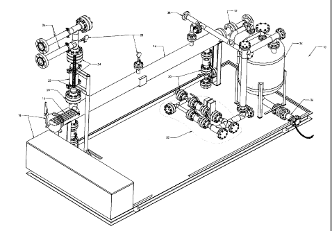
Figure 1 depicts generally at 10 a horizontal-vertical (H-V) sand filter
combination apparatus. In this H-V embodiment, an inlet is shown at 12,
pressure vessel/velocity slowdown chamber at 14, hydrate-knock-out baffle at
16, sand clean-out access at 18, and nozzle/transition point from primary to
secondary screening stages at 20. Pressure vessel for third stage of
processing/cartridge is depicted at 22 comprising wire wrapped screen 24.
27
CA 02877020 2015-01-12
Outlet or back flush is provided at 26. A downstream pressure indicator for
auto/manual dump indication is provided at 28 and PSV line at 38.
In regards to blowdown, blowdown spooling is provided at 30, blowdown valve
and by-pass at 32, blowdown vessel at 34 and blowdown drain/clean out at 36.
Figure 2 likewise shows a side plan view of elements 14-18, 22-32, 36, and 38.
Figure 3 likewise shows a side plan view of elements including 12, 14 18, 22,
24,
26 and 28. Additionally, hammer closure 17 is shown.
Figure 4 is side view of the horizontal/vertical sand filter apparatus
illustrating
three stages/steps of filtration (described above), as follows: initial
section/stage
40, secondary section/stage 42 and coalescing section/stage 44.
Figure 5 is a side plan view of the area in which the initial section or step
one 40
is performed. Inlet 12 provides an entry point to pressure vessel/velocity
slowdown chamber 14 (also referred to interchangeably herein as "horizontally
disposed gravity knock-out tube"). Outlet port 43 provides one means of egress
for frac sand. Outlet port 48 provides a further means of egress for frac
sand.
Direction of flow of gas/liquid frac sand/solids from inlet 12 to port 46 is
shown
28
CA 02877020 2015-01-12
at 47. Just below nozzle 20, providing transition zone into the secondary
stage of
processing is port 46, which in situ is in operational engagement with nozzle
20.
Figure 6 is a side view of a vertical screen/wire-wrapped slotted screen and
gas
flow diagram. Gas and remaining frac sand 50 from slowdown chamber 14
travels through nozzle 20 to cartridge 22 comprising wire wrapped screen 24.
Frac sand stopped by wire wrapped screen 24. Clean gas 52 exits cartridge 22
at
52.
Figure 7 is a side plan view and Figure 8 a perspective view of a
horizontal/horizontal (H-H) sand filter apparatus shown generally at 54. In
this
H-H embodiment, an inlet is shown at 56, pressure vessel/velocity slowdown
chamber (for primary processing) at 58, sand clean-out--screen access at 60,
and
nozzle/transition point from primary to secondary screening stages at 62.
Horizontal screen 64 is disposed within cartridge 65 (within coalescing
section
104) (see Figure 10). Outlet or back flush is provided at 66. An upstream/
downstream pressure indicator for auto/manual dump indication is provided at
68 and PSV line at 78.
In regards to blowdown, there is provided drain clean out channel 70, blowdown
piping and valves 72, blowdown/sand storage chamber/vessel 74, and
blowdown drain 76.
29
CA 02877020 2015-01-12
Figure 9 is a side plan view of parts of a horizontal/horizontal sand filter
apparatus of Figures 7 and 8.
Figure 10 is a side plan view of a horizontal/horizontal sand filter apparatus
illustrating three stages/steps of filtration as follows: initial
section/stage 100,
secondary section/stage 102 and coalescing section/stage 104.
Figure 11 is a side plan view of the "primary vessel" (area in which the
initial
section or step one is performed) namely sand accumulation and gas flow in
which the initial section or step one 100 is performed. Inlet 80 provides an
entry
point to pressure vessel/velocity slowdown chamber 58 (also referred to
interchangeably herein as "horizontally disposed gravity knock-out tube").
Outlet
port 82 provides one means of egress for frac sand. Outlet port 84 provides a
further means of egress for frac sand. Direction of flow of gas/liquid frac
sand/solids from inlet 80 to port 86 is shown at 88. Just below nozzle 62,
providing transition zone into the secondary stage of processing is port 86,
which in situ is in operational engagement with nozzle 62.
Figure 12 is a side plan view of a sand filter/gas flow in horizontal screen
chamber/cartridge 65 (comprising wire-wrapped slotted screen 64). Gas and
remaining frac sand 89 from slowdown chamber 58 travels through nozzle 62 to
cartridge 65 comprising wire wrapped screen 64. Frac sand is stopped by wire
wrapped screen 64. Clean gas exits cartridge/chamber 65 at 90.
CA 02877020 2015-01-12
Figure 13 is a perspective exploded view of vertically oriented tubular screen
chamber 22 comprising a wire wrapped slotted screen 24 configured to filter
out
fine particulates and wherein wire wrapped slotted screen is housed within a
removable cartridge wherein Figure 13 illustrates removable cartridge in
place.
Figure 14 is a perspective view of vertically oriented tubular screen chamber
22
comprising a wire wrapped slotted screen 24 configured to filter out fine
particulates and wherein wire wrapped slotted screen is housed within a
removable cartridge, wherein Figure 14 illustrates removable cartridge with
screen removed for cleaning/replacement.
Figure 15 is a side view of vertically oriented tubular screen chamber 22 with
removable cartridge 24 in place.
Figure 16 is a further embodiment of vertically oriented tubular screen
chamber
with removable cartridge with screen removed for cleaning/replacement.
Figure 17 is a side plan view to assist in the understanding of the
orientation and
operation of the blowdown valves. There are a plurality of options for
blowdown
operation including two manual options and one automatic option.:
Option 1 Manual
1. Close Valve A
2. Close Valve B
31
CA 02877020 2015-01-12
3. Open Valve C
4. Open Valve B
5. Open Valve C
This is a highly effective and possibly the most effective blowdown means.
Option 2 Manual
1. Open Valve C
2. Close Valve C
Option 1 Automatic
1. At set differential pressure, Valve A shuts, delayed timer at Valve B
shuts.
Delayed timer at Valve C opens for a programmed period of time (for example 10
seconds).
2. Sequence in reverse order of step 1.
3. If pressure differential outside of set points, the process is repeated
until clean
out is completed.
4. If there is failure to clean after pre-determined number of attempts (for
example three), an technician/operator is called for service.
Here is a brief explanation of the graph of Figure 18: to the "left" X2 is
shown the
amount of liquids/water/oil which can flow through the screen before there is
an
impact to Gas flow. To the right of X2 is shown that increasing liquid flow
will
reduce the Flow Capacity of the Gas in the sand filter. The five lines
indicate
32
CA 02877020 2015-01-12
different operating pressures of gas entering the units, from 1000psi to 5000
psi
as follows:
A-1000 psi
B-2000 psi
C-3000psi
D-4000psi
E 5000psi
As will be apparent to those skilled in the art, the various embodiments
described above can be combined to provide further embodiments. Aspects of
the present systems, methods and components can be modified, if necessary, to
employ systems, methods, components and concepts to provide yet further
embodiments of the invention. For example, the various devices and methods
described above may omit some parts or acts, include other parts or acts,
and/or
execute acts in a different order than set out in the illustrated embodiments.
Further, in the methods taught herein, the various acts may be performed in a
different order than that illustrated and described. Additionally, the methods
can omit some acts, and/or employ additional acts.
These and other changes can be made to the articles in light of the above
description. In general, in the following claims, the terms used should not be
33
CA 02877020 2016-01-07
construed to limit the invention to the specific embodiments disclosed in the
specification and
the claims, but should be construed to include all possible embodiments along
with the full
scope of equivalents to which such claims are entitled. Accordingly, the
invention is not limited
by the disclosure, but instead its scope is to be determined by the following
claims:
Example:
Flow Rate Calculations
Rooked: crv - Flow rate efa a rnaiinuin itikt velocity &
acoirtrol WI velocity
tuning 10fra'sir.).a.mri.:.M".,...2(r ctiNtivcric'SS f thic smelt
Clive& 14.7 psis atmosphesie pressure
Phlkt pug: pres.sure ri./ inlet (in 1000psi
= 1000-5000 incicmcnO
Pd a 10 psi press= (hop
Pi = P Pinlet ebt.o I ate presntre (et inlet
dl - 2" ID or pipe a inlet
d2 = I I^ ID of vessel
Specific Weight Ann. Pressure
0Ø53813 lix=ft) 4273K
As.suming Expansion of gas ffont inlet to vosol itb isothermal dr isentrupic.
Calculating maximum possible inlet velocity a MA W1vlj
2(P:a a Pa)
¨
PI
Where: pl = the density of gas (0 Wet pressure (5000psi)
y 111 alp )
= _____________________________________________
9 9
Using inlet pressure of 5000psi
ik\ (5014J)
(0.053813
ft---V 4. 14.7 )
pi
32.174 ft s2
040
0-570$71097 = 037071097 Slugsle
/oft
120014.7 ¨ 1OpLa
¨ I ____________________________________________
J0.570571097
/13
1/1 = 13-2.4/I() I 386 L
34
CA 02877020 2016-01-07
. .
adeuialle the Flow Throtich the N'essel From 1000-5000osi (not adjusted for
densits. of alis)
2) Flow Through Vessel & Velocity Inside Vessel l'ii 5000psi
Qa= riAi
0,- 132.4491386140r/4)(2/12)zfr
s
a, == 2.88959195 f3-4
Vat = gal:4:,
2.88959195 .:.4 -.
V241¨ ________________________ 5
(1114)(11/12)2
4.378483921 f tis
3) Volumetric Flow of Gas (Volume calculated at Atm.
Pressure & 273K)
Q.i.=
Q.".= 2.88959195 Lc- s4 1.-IV
Qn = 985.7439968 E.3...( ICI
344 , ,=;1 14
$ OODDO)
Qva - 85.16828132 1v1h4SCFID (ri, 100% Screen Effectiveness
Qva ., 68.13462506114MSCF/D 0, 80% Semen Effectiveness
Qva - 51.10096879 MMSCP13 (".i.. 60% Screen Effectiveness
Qva =34.06731253 MMSCE/D (a. 40% Screen Effectiveness
Qva = 17.03365626 MMSCF/D is. 20% Screen Effectivenes.s
Qva = 0 MMSC:Fill 4 0% Screen Effectiveness
CA 02877020 2016-01-07
Required: Qf = Flow rate of fluid @ maximum inlet velocity & a controlled
velocity
assuming 100%/80%/60%/40%/20%/0% effectiveness of the screen
Given: P1= 5000 psi inlet pressure
P2= 4600 psi pressure in the outlet spool
y = 62.4 lb/NI specific weight of water
v = 7.37 x 10^(-6) ft9s kinematic viscosity of water
d= 2" ICI of pipe at inlet
Assuming: No change in potential energy in the fluid as it travels through the
vessel
4) Calculate maximum velocity of 100% water/frac sand solution
4.1) Calculate flow rates
V
, 2pd 2(Pi -P2)
¨ ¨pi ¨ ____________________
velocity at inlet
rig
36
CA 02877020 2016-03-23
2(5000 ¨ 4600)psi
= _____________________
lb
62.4T.F
t
/32=174L
= 20.30978039 ft/s
Q1 = VA
Q1 = 20.30978039 [1*
s 4
(2/12)2)ft2
Q1 = 0.443090672 ft3/s
V2 Q1/ A2 --= velocity in vessel
0.443090672 ft3/s
V2 = ______________
a (11/12)2) ft2
V2 = 0.671397697 ft / s
4.2) Calculate flow across screen given:
= 4" NPS Pipe, 4.57" OD
= 0.01 slot size
= 0.140" x 0.297" wrap
= screen length; L = 60"
Open Area (%)¨ __ 0.14+0.01 * 100% = 6.6%
Open Area (in2/ft)= err = ODscreen)*12-ifi (Open Area (%))
Open Area = (n- * 4.57in) * 12pt * !_o
Open Area =11.48566273 in2/ ft
37
CA 02877020 2016-01-07
, .
4.3) Flow cap across screen
Open Area
Flow Cap=
(231 inl
gallon
in
1277 )/
(VaCTOSS screen _
St;) (6 lii7)\
i
a) Using assumed velocity across screen of 0.1 Ws
11.48566273 (in2ift)
Flow Cap = ,(
i 231 in3 \
gallon 1
12in
TE i \
ft) ( ,... n s '1
(Vacross screen 77,/ ,,,.,,,, -1,7-11 )
\ 1
Flow Cap=3.579946825 illaic-2-'
ft + min
.
,1
\
t gallon I , ?I" 3
ni"
Qa = Flow Cup _______________________ * (0.0254 1) * 60 * 24 imur
L
______________________________________________________________ * ir * CaLlse
____ *
kit * Milt) 4, 231 gallon In) hour day
re" '\(12iji)-2/
gallon in3 m hour 601n
Q. = 3.579946825(' ___________ ) * 231 + (0.0254 m in )3* 60
_________________ 4 24¨+ if * 4.57in *( , 2
ft * min gallon In hour day
k - fm\t]
nt3
Q. = 116.7365969 ¨
(
day)
b) Using maximum inlet velocity of 100% fluid/frac sand solution
a
11.48566273 (. in / ft)
Flow Cap =
in.'
231 _________________________
( gallon) /
(
12¨
,
,
/ (0.671397697L) (60-L-5.--)
s nun
Flow Cap- 24.0356804
ft. min
37A
CA 02877020 2016-01-07
. .
min
gallon in3 m)3 hour
L
(2,b = Flow Cap (' ______________ )*231 ____ * (0.0254 * 60 * 24
_________________ day * Tr * 00,õõõ *
ft * min gallon In hour
((12 M2)
hour It
i
3 3
60in )
Qh = 24.03568054(8(111ml ),* 231- in *
(0.0254m) 4, 60 *24 . , 4,5.7in
Min
f t * min gallon , In hour day
i-n -
(0270
in3
Qt, = 783.365969 ¨day
(
c) Using controlled velocity of 40 ft/s at inlet
11.48566273 (in 2i)
Flow cup = _____________ /231 in 3
_gallon
in
/
(L3223140511 (60S)
nun
Flow Cap= 47.33813985 _______________
f r = mm
/
gallon in3 irt)3 min
hour I.
Qc, = Flow Cap (f t * _______ min)* 231 gallon* (0.0254 In * 60 hour * 24
__________ day * it * ()Duman *I , 2)
\ (1211
77
\
gallon in 3m 3 3 min hour
60thQ, = 47.33813985 () 4, 231 =* (0.0254¨)In day * 60 hour * 24 *
n* 4.57in
ft . min
* _____
gallon
in 2
\ (12 TT) j
i n13
= 1543.624423
Oa))
Using results from c):
Find flow rate through screen at 0%/20%/40%/60%/80%/100% of the screens
effective area, flow is the same
for all inlet pressures
(2õ = 1543424423 m'/day at 100% screen effectiveness
Q, 1234.899538 miiday at
80% screen effectiveness
Qf =926.1746538 m3/day at 60% screen effectiveness
Q,. --617A497692 m3Iday at 40% screen effectiveness
Q, 408.7248846 neiday at 20% screen effectiveness
Qi: 0.0 m3.1day at 0% screen e f f ectiveness
37B