Note: Descriptions are shown in the official language in which they were submitted.
CA 02877504 2015-01-13
- 1 -
BIOPSY DEVICE WITH VARIABLE SPEED CUTTER ADVANCE
[001] FIELD OF THE INVENTION
[002] The present invention relates in general to biopsy devices and, more
particularly,
to methods and devices for advancing and driving a cutter in a biopsy device.
BACKGROUND OF THE INVENTION
[003] The diagnosis and treatment of patients with cancerous tumors is an
ongoing
area of investigation. Medical devices for obtaining tissue samples for
subsequent sampling are known in the art. For instance, a biopsy instrument
now
marketed under the trade name MAMMOTOME is commercially available for
use in obtaining breast biopsy samples.
[004] The following patent documents disclose various biopsy devices: US
6,273,862
issued Aug 14, 2001; US 6,231,522 issued May 15, 2001; US 6,228,055 issued
May 8, 2001; US 6,120,462 issued September 19, 2000; US 6,086,544 issued
July 11,2000; US 6,077,230 issued June 20, 2000; US 6,017,316 issued January
25, 2000; US 6,007,497 issued Dec. 28, 1999; US 5,980,469 issued Nov. 9,
1999; US 5,964,716 issued Oct 12, 1999; US 5,928,164 issued July 27, 1999; US
5,775,333 issued July 7, 1998; US 5,769,086 issued June 23, 1998; US
5,649,547 issued July 22, 1997; US 5,526,822 issued June 18, 1996; US
2003/0199785
CA 02877504 2015-01-13
-2-
published Oct 23, 2003; US 2003/0199754 published Oct 23, 2003; US
2003/0199754 published Oct 23, 2003.
SUMMARY OF THE INVENTION
[005] It can be desirable to vary the translational speed of a rotating and
translating
cutter in a biopsy device. For instance, it may be desirable to have the
cutter
translate at different rates. By way of example, US Patent 6,120,462 discloses
a
method for controlling a biopsy device.
[006] While motor speed can be varied corresponding to a desired variation in
translational speed of a cutter, it may be undesirable to require operation of
a
motor at significantly different speeds, or to incorporate complex controls
for
varying a motor speed. A transmission assembly having a gear train could be
employed to vary a cutter translation speed, but such an approach may add
undesired complexity or weight to the biopsy device.
[007] In one embodiment, the present invention provides a biopsy device
comprising
a cannula having a tissue receiving port; a tissue cutter disposed coaxially
with
the cannula, the cutter adapted for translation relative to the cannula; and a
variable pitch member operatively associated with the tissue cutter for
providing
variation in the translational speed of the tissue cutter. The tissue cutter
can be
adapted for translation and rotation within the cannula during a portion of
the
cutter travel. A motor, such an electric motor, can be employed for rotating
the
variable pitch member. The motor can provide rotation at a desired speed, and
the
CA 02877504 2015-01-13
- 3 -
variable pitch member can be employed to vary the translational speed of the
cutter independently of the rotational speed of the motor.
[008] The variable pitch member can be in the form of a variable pitch
rotation shaft
having a threaded portion of varying pitch for providing a variable pitch cam
surface. The biopsy device can be a handheld device which includes a first
motor for providing rotation of the variable pitch member and a second motor
for providing rotation of the cutter. The variable pitch rotation shaft can
include a relatively coarse pitch portion for advancing the cutter at a
relatively
rapid rate prior to tissue cutting, and a relatively fine pitch portion for
advancing the cutter at a relatively slower rate during tissue cutting.
[009] The variable pitch cam surface of the variable pitch rotation shaft can
be in the
form of a cam slot formed in the outer surface of the shaft. A cam nut can be
supported on the rotated shaft, and can be translated along the length of the
shaft at a speed that is a function of the pitch of the cam slot on the shaft.
Depending on the direction of rotation of the shaft, translation of the cam
nut
can provide translation of the cutter in a forward (distal) or reverse
(proximal)
direction.
[009A] In an aspect, there is provided a biopsy device comprising: an outer
cannula
having a lateral tissue receiving port; an inner tubular cutter disposed for
translation within the cannula; a rotating member having a screw thread
feature of varying pitch, wherein the rotating member is operatively
associated
with the cutter for varying the translational speed of the cutter as the
tissue
cutter is advanced in relation to the tissue receiving port.
[009B] In an aspect, there is provided a biopsy device comprising: a cannula
having a
lateral tissue receiving port; a tissue cutter disposed coaxially with the
cannula, the cutter adapted for translation relative to the cannula; and a
variable pitch member operatively associated with the tissue cutter for
CA 02877504 2015-01-13
- 3a -
providing variation in the translational speed of the tissue cutter as the
tissue
cutter is advanced in relation to the tissue receiving port.
[009C] In an aspect, there is provided a biopsy device comprising: an outer
cannula
having a lateral tissue receiving port; an inner tubular cutter disposed for
translation within the cannu.la; a rotating member having a screw thread
feature of varying pitch, wherein the rotating member is operatively
associated
with the cutter for varying the translational speed of the cutter, and wherein
the rotating member is adapted to rotate without translation of the cutter in
at
least one position of the cutter.
BRIEF DESCRIPTION OF THE DRAWINGS
[0010] While the specification concludes with claims particularly pointing out
and
distinctly claiming the present invention, it is believed the same will be
better
understood by reference to the following description, taken in conjunction
with the accompanying drawings in which:
CA 02877504 2015-01-13
-4-
[0011] FIG. 1 is an isometric view of a biopsy instrument according to one
embodiment
of the present invention, which includes a handpiece for the collection of
soft
tissue;
[0012] FIG. 2 is an isometric view of the handpiece of FIG. 1, showing a probe
assembly prior to attachment to a holster;
[0013] FIG. 3 is an isometric view of the underside of the holster and probe
assembly
shells, wherein the holster lower shell includes a slot for the removable
attachment to a latch on the probe assembly lower shell;
[0014] FIG. 4 is an isometric view similar to FIG. 3, illustrating the
removable
attachment of the holster and probe assembly lower shells;
[0015] FIG. 5 is an exploded isometric view of the probe assembly illustrated
in FIG. 2;
[0016] FIG. 6 is an isometric view of the probe assembly of FIG. 2, with the
upper shell
removed to reveal the internal components;
[0017] FIG. 7 is an exploded view of the rotary drive shaft and lower probe
assembly
shell;
[0018] FIG. 8 is a partial isometric view of the translation shaft assembly
illustrating the
cam track and cam nut;
[0019] FIG. 9 is a top view of the cutter rotation and translation shaft
assemblies;
[0020] FIG. 10A is a top view of the cam nut follower and translation shaft;
CA 02877504 2015-01-13
-5-
[0021] FIG. 10B is a section view taken along section A-A in FIG. 10A;
[0022] FIG. 11 is an exploded isometric view of the translation shaft
assembly;
[0023] FIG. 12A is a top view of the cam nut adjacent the proximal end of the
translation shaft;
[0024] FIG. 12B is a section view taken along section A-A in FIG. 12A;
[0025] FIG. 13A is a top view of the cam nut at the proximal most position of
the
translation shaft;
[0026] FIG. 13B is a section view taken along section A-A in FIG. 13A;
[0027] FIG. 14A is a top view of the probe assembly with the upper shell
removed to
reveal the cutter in a first, fully retracted position;
[0028] FIG. 14B is a top view of the probe assembly with the upper shell
removed to
reveal the cutter in a third position, wherein the distal end of the cutter is
immediately proximal to the port;
[0029] FIG. 14C is a top view of the probe assembly with the upper shell
removed to
reveal the cutter in a fourth, fully deployed position;
[0030] FIG. 15 is an exploded isometric view of the holster showing a first,
double
motor embodiment of the present invention;
CA 02877504 2015-01-13
-6-
[0031] FIG. 16 is a rear isometric view of the holster assembly of FIG. 15,
wherein the
holster upper shell is detached to reveal the double motor assembly;
[0032] FIG. 17 is an exploded isometric view of the double motor assembly of
FIG.16;
[0033] FIG. 18 is an exploded isometric view of the holster depicting a
second, single
motor embodiment of the present invention;
[0034] FIG. 19 is a rear isometric view of the holster of FIG. 18, wherein the
holster
upper shell is detached to reveal the single motor assembly;
[0035] FIG. 20 is an exploded isometric view of the single motor assembly of
FIG.19;
[0036] FIG. 21 is an exploded isometric view of a probe assembly for the
second, single
motor embodiment;
[0037) FIG. 22 is an isometric view of the probe assembly of FIG. 21, with the
upper
shell removed to reveal the internal components;
[0038] FIG. 23 is a schematic diagram of a vacuum system in accordance with
the
present invention;
[0039] FIG. 24A is a first portion of a flow diagram pertaining to the
operation of the
cutter, showing the control unit logic for when the cutter translates from the
first
position to the second position;
CA 02877504 2015-01-13
- 7 -
[0040] FIG. 24B is a second portion of a flow diagram pertaining to the
operation of the
cutter, showing the control unit logic for when the cutter translates from the
second to the third position;
[0041] FIG. 24C is a third portion of a flow diagram pertaining to the
operation of the
cutter, showing additional control unit logic for when the cutter translates
from
the second to the third position;
[0042] FIG. 24D is a fourth portion of a flow diagram pertaining to the
operation of the
cutter, showing the control unit logic for when the cutter translates from the
third
to the fourth position;
[0043] FIG. 24E is a fifth portion of a flow diagram pertaining to the
operation of the
cutter, showing the control unit logic for terminating operation of the cutter
after
the cutter has reached the fourth position; and
[0044] FIG. 25 is a graphical representation of an exemplary current profile
for the
translation motor.
DETAILED DESCRIPTION OF THE INVENTION
[0045] The present invention pertains to a biopsy device for obtaining a
tissue portion
from within a body and, in particular, to controlling the speed of a cutting
instrument within a core biopsy device. An example of a core biopsy device is
described in U.S. Patent No. 6,086,544 issued to Hibner et al. FIG. 1 shows a
core sampling biopsy instrument according to the present invention comprising
a
handpiece identified
CA 02877504 2015-01-13
-8-
generally by the numeral 20, a vacuum system 22, a control unit 24, and a
power
source 26. Handpiece 20 is preferably lightweight and ergonomically-shaped to
be easily manipulated by an operator's hand. Handpiece 20 includes a probe
assembly 28 and a detachably connected holster 30.
[0046] Probe assembly 28 is connected to vacuum system 22 by a first vacuum
tube 32
and a second vacuum tube 34. First and second vacuum tubes 32, 34 are
detachably connected to vacuum system 22 by a first connector 36 and a second
connector 38 respectively. First connector 36 has a male portion 40 and a
female
portion 42 attached to first vacuum tube 32. Second connector 38 has a female
portion 44 and a male portion 46 attached to second vacuum tube 34. Connector
portions 40, 42, 44 and 46 are attached in this manner to prevent the
accidental
switching of first and second tubes 32 and 34 to vacuum system 22. Holster 30
includes a control cord 48 operationally connecting the handpiece 20 to
control
unit 24 and power source 26. Control cord 48 provides electrical power and
control information to handpiece 20.
[0047] Because handpiece 20 is manipulated by the operator's hand rather than
by an
electromechanical arm, the operator may steer the tip of handpiece 20 with
great
freedom towards the tissue mass of interest. The surgeon has tactile feedback
while doing so and can thus ascertain, to a significant degree, the density
and
hardness of the tissue being encountered. In addition, handpiece 20 may be
held
approximately parallel to the chest wall of the patient for obtaining tissue
portions closer to the chest wall than may be obtained when using an
instrument
mounted to an electromechanical arm. Those skilled in the art may appreciate
that a mount or "nest" could be provided to hold handpiece 20 securely to the
movable arm of an X-ray stereotactic table in the event that it is desirable
to use
an X-ray stereotactic table.
CA 02877504 2015-01-13
-9--
[0048] FIG. 2 shows probe assembly 28 disconnected from holster 30. Probe
assembly
28 includes an upper shell 50 and a lower shell 52 each of which may be
injection molded from a rigid, biocornpatible plastic, such as a
polycarbonate.
Upon final assembly of probe assembly 28, upper and lower shells 50, 52 can be
joined together along a joining edge 54 by any of a number of methods well
known for joining plastic parts, including, without limitation, ultrasonic
welding,
snap fasteners, interference fit, and adhesive joining. Similarly, holster 30
includes an upper shell 56 and a lower shell 58 which also may be injection
molded from a rigid, biocompatible plastic, such as a polycarbonate, and
joined
together along edge 60 by any suitable method for joining plastic parts.
[0049] FIGS. 3 and 4 show the bottom portions of holster 30 and probe lower
shell 52.
As shown in the figures, a probe latch 62 can be molded into lower probe shell
52 for detachably connecting probe assembly 28 to holster 30. Probe latch 62
is
a cantilevered beam and can be deflected downwardly by a force applied to a
latch ramp surface 64. Probe latch 62 further comprises a latch projection 66
for
insertion into a holster slot 67 as a proximal end of probe assembly 28 is
inserted
into holster 30. Ramp surface 64 is deflected downwardly by interaction
between the surface 64 and an inside surface 65 of holster shell 30. Probe
latch
62 retainably snaps into a slot key 68 when probe assembly 28 is fully
inserted
into holster 30. To remove probe assembly 28 from holster 30, the operator
manually depresses projection 66 until ramp surface 64 disengages from slot
key
68. Projection 66 may then be pulled axially through slot 67 until the probe
assembly 28 and holster 30 are separated.
[0050] Returning now to FIGS. 1 and 2, which show that electrical switches are
mounted on holster upper shell 56 to enable the operator to use the handpiece
20
CA 02877504 2015-01-13
-10-
with a single hand. These switches can include a two position rocker switch 72
for actuating the motion of the cutter (e.g. forward movement of rocker switch
72
moves the cutter in the forward (distal) direction for tissue sampling and
rearward movement of the rocker switch 72 actuates the cutter in the reverse
(proximal) direction to position a tissue sample in sample retrieval surface
74),
and a vacuum switch 76 for actuating vacuum system 22. One-handed operation
allows the operator's other hand to be free, for example, to hold an
ultrasonic
imaging device. A ridge 78 on the distal end of holster 30 is provided to
assist
the operator in grasping handpiece 20 and operating switches 72, 76. Probe
assembly shells 50, 52 may also be contoured to improve the operator's grip on
the instrument during use.
[0051] First and second vacuum tubes 32, 34 can be made from a flexible,
transparent or
translucent material, such as silicon tubing, PVC tubing or polyethylene
tubing.
This enables visualization of the material flowing through the tubes 32, 34.
As
shown in FIGS. 3 and 4, one or more slots such as, for example, that indicated
by
numeral 70, can be provided in holster shell 58 to provide clearance for first
and
second vacuum tubes 32, 34. An open area at the distal end of probe assembly
28 allows access to sample retrieval surface 74. The operator or an assistant
can
retrieve a tissue sample from surface 74.
[0052] FIG. 5 provides an exploded isometric view of probe assembly 28. A
biopsy
needle, including a piercer 80 is located at a distal end of probe assembly 28
for
insertion into the surgical patient's skin to obtain a tissue sample. Piercer
80
comprises a cannula having an elongated, metallic piercer tube 82 and an
associated lumen 84 extending along the axial length of the tube. Adjacent the
distal end of piercer tube 82 is a lateral tissue receiving port 86 for
receiving the
tissue to be extracted from the surgical patient. Joined alongside piercer
tube 82
CA 02877504 2015-01-13
- 11 -
is an elongated vacuum tube 88 having a vacuum lumen 90. Piercer tube 82 can
be formed of any suitable material, including metal or plastic. As shown in
FIG.
6, piercer lumen 84 is in fluid communication with vacuum lumen 90 via a
plurality of vacuum holes 92 located in the bottom of the tissue aperature
defined
by port 86. These vacuum holes 92 are small enough to remove fluids, but not
large enough to allow excised tissue portions to be removed through first
vacuum tube 32, which is fluidly connected to vacuum lumen 90 of vacuum tube
88. A sharpened tip of piercer 80 can be formed by a separate piercing
endpiece
94 attached to the distal end of the piercer. Endpiece 94 can have a two-
sided,
flatshaped point, or other shapes suitable for penetrating the tissue of a
surgical
patient.
[0053] The proximal end of piercer 80 is attached to a union sleeve 96 having
a
longitudinal bore therethrough, and a transverse opening 102 into a widened
center portion of the bore. An elongated, metallic, tubular cutter 104 is
axially
aligned within the longitudinal bore of union sleeve 96 and piercer lumen 84
of
piercer 80 so that the cutter may slide easily in both the distal and proximal
directions. A cutter guide 106 is disposed in the proximal end of union sleeve
96.
Cutter guide 106 can be in the form of a metallic funnel-shaped guide that
ensures proper alignment between cutter 104 and union sleeve 96. Union sleeve
96 and cutter guide 106 are supported between probe upper and lower shells 50,
52 by integrally-fonned support ribs 107 extending from lower shell 52, and an
integrally-formed housing 108 at the distal end of upper shell 50. These
integrally-formed supports 107, 108, along with a slot 110 and opening 112
formed in probe shells 50, 52, ensure proper alignment between the cutter 104
and union sleeve 96 so that the cutter may be translated easily in both the
distal
and proximal directions. The distal end of first vacuum tube 32 is attached to
a
CA 02877504 2015-01-13
-12-
polymeric vacuum fitting 113 that inserts tightly into transverse opening 102
of
union sleeve 96. Opening 102 is in fluid communication with lumen 90, and
allows the communication of fluids in piercer lumen 84 to a vacuum reservoir
in
vacuum system 22 via vacuum holes 92.
[0054] A cutter lumen 114 extends through substantially the entire length of
cutter 104.
An elongated, hollow, tubular tissue remover 115 can be disposed coaxially
within cutter lumen 114, such that cutter 104 may translate along a length of
the
remover 115. Tissue remover 115 may be metallic or non metallic. Second
vacuum line 34 can be fluidly attached to the proximal end of tissue remover
115
to provide vacuum to the cutter lumen 114 via a central passageway extending
through the tissue remover 115. Second vacuum tube 34 exits lower shell 52
alongside the first vacuum tube out an opening 117. A strainer 119 is attached
to
the distal end of tissue remover 115 to prevent fragmented tissue pieces from
passing through the remover and into vacuum system 22.
[0055] The tissue remover 115 can be held stationary with respect to the lower
shell 52
and can be supported by a pair of proximal supports (not shown) on the inside
of
probe lower shell 52. Second vacuum line 34 provides vacuum through cutter
lumen 114 via the hollow remover 115, which vacuum can be used to assist in
drawing tissue into tissue receiving port 86 when the distal end of cutter 104
is
positioned proximal of the port.
[0056] The distal end of cutter 104 is sharpened to form a cutter blade 116
for cutting
tissue held against the blade as cutter 104 is rotated. The proximal end of
cutter
104 is attached inside an axial bore of a cutter gear 118. Cutter gear 118 may
be
metallic or polymeric, and includes a plurality of cutter gear teeth 120. Each
of
CA 02877504 2015-01-13
=
-13-
the gear teeth 120 has a typical spur gear tooth configuration as is well
known in
the art.
[0057] Referring to FIGS. 5 and 6, cutter gear 118 is driven by an elongated
rotary
drive shaft 122 having a plurality of drive gear teeth 124 designed to mesh
with
cutter gear teeth 120. In this embodiment, drive gear teeth 124 extend
approximately the entire length of drive shaft 122 and engage cutter gear
teeth
120 throughout the translation of cutter 104. Drive gear teeth 124 are in
continual engagement with cutter gear teeth 120 to rotate cutter 104 whenever
drive shaft 122 is rotatably driven. As will be described in more detail
below,
drive shaft 122 rotates cutter 104 as the cutter advances distally through
tissue
receiving port 86 for the cutting of tissue. Drive shaft 122 may be injection
molded from a rigid engineering plastic such as liquid crystal polymer
material
or, alternatively, could be manufactured from a metallic or non-metallic
material.
Drive shaft 122 could also be extruded from aluminum or machined from a
metallic material.
[0058] As shown in FIG. 7, drive shaft 122 includes a first axial end 126
extending
distally from the shaft. Axial end 126 is supported for rotation within probe
lower shell 52 by a drive shaft interface 127 molded on the inside of the
probe
shell. Similarly, a second axial end 128 extends proximally from rotary drive
shaft 122 and is supported in a second interface 130 also molded on the inside
of
probe lower shell 52. An 0-ring 131 and bushing 133 may be provided on each
axial end 126, 128 so as to sit within interfaces 127, 130 when rotary drive
shaft
122 is mounted in probe shell 52. Bushing 133 reduces friction at the drive
shaft
interfaces 127, 130, while 0-ring 131 isolates vibrations in rotary drive
shaft 122
from the rest of probe assembly 28. Bushing 133 could also be used without 0-
ring 131 at interfaces 127, 130. A drive slot 132 is formed in axial end 128.
CA 02877504 2015-01-13
-14-
Drive slot 132 interfaces with a corresponding drive slot formed in a motor
drive
shaft 134, or other rotational drive input for providing rotation of the drive
shaft,
as will be described further below.
[0059] Referring now to FIGS. 8 and 9, a cam nut 136 is provided in probe
assembly 28
to hold cutter gear 118 and carry the cutter gear and attached cutter 104
during
translation in both the distal and proximal directions. Cam nut 136 is
preferably
molded from a rigid polymer and has a cylindrically shaped bore 138 extending
axially therethrough. A pair of J-shaped hook extensions 140 extend from one
side of cam nut 136. Hook extensions 140 rotatably support cutter 104 on
either
side of cutter gear 118 to provide proximal and distal translation of gear 118
and
cutter 104 during proximal and distal translation of cam nut 136. Hook
extensions 140 align cutter 104 and cutter gear 118 in the proper orientation
for
cutter gear teeth 120 to mesh with drive gear teeth 124.
[0060] Cam nut 136 is supported on shaft 142 for translational movement along
translation shaft 142. Shaft 142 extends through cam nut bore 138 in parallel
with cutter 104 and rotary drive shaft 122. Translation shaft 142 may be made
from aluminum or another similar material, and includes a path, such as a path
in
the form of lead screw thread groove 144 which can be machined or otherwise
formed in the outer circumference of the shaft 142. The thread groove 144 can
be generally helical. The pitch of lead screw thread groove144 may vary
between the proximal and distal ends of translation shaft 142. In the
embodiment
described herein, the lead screw pitch varies from a coarser or more widely
spaced pitch at the proximal portion of the shaft, to a finer, more closely
spaced
pitch at the distal portion of the shaft. The particular pitch width of thread
groove 144, as well as the ratio of wide to narrow pitch width along the
length of
CA 02877504 2015-01-13
-15-
the translation shaft, will vary in the present invention depending upon the
desired operation of cutter 104.
[0061] In the figures, translation shaft 142 is shown with a right hand thread
so that
clockwise rotation (looking from the proximal to the distal direction) causes
cam
nut 136 to translate along shaft 142 in the proximal direction, while the
reverse
rotation of shaft 142 causes cam nut 136 to move in the distal direction.
However, the thread direction could also be reversed, with the particular
direction of the screw thread depending upon the application and rotary drive
input.
[0062] As shown in greater detail in FIGS. 10A and 10B, cam nut 136 is molded,
machined, or otherwise formed to include a receiver hole 150 extending
perpendicular to bore 138. A cam follower pin 152 is positioned within
receiver
hole 150 such that a portion of the pin extends beyond cam nut 136 and into
lead
screw thread groove 144 of translation shaft 142 as the thread passes through
bore 138. Lead screw thread groove 144 forms a path in which to guide cam
follower pin 152 about the surface of translation shaft 142 as the shaft is
rotated.
Cam follower pin 152 can be a metallic, machined pin that is assembled as part
of cam nut 136 to create the interface between the cam nut 136 and translation
shaft 142. In the embodiment shown, cam follower pin 152 is assembled with an
interference fit in cam nut receiver hole 150. Alternatively, pin 152 could be
inserted by other methods, such as by insert molding or with screw threads. In
yet another embodiment, pin 152 can be supported on cam nut 136 so as to be
able to move radially and so "float" in thread groove 144.
[0063] As shown in FIG. 10B, cam follower pin 152 sits within cam receiver
hole 150
and can have a tapered or otherwised shaped tip, as indicated by angled
surface
CA 02877504 2015-01-13
-16-
156, that is shaped to match the profile of cam path 144. Cam path 144 can
have
a tapered profile. The angled surface 156 allows cam follower pin 152 to
freely
slide within the tapered pathway formed by lead screw thread 144, and adapt
easily to the changing pitch of the thread and/or width of the thread 144.
[0064] Returning to FIGS. 8 and 9, a slot 158 is provided in the proximal end
of
translation shaft 142 for attaching the shaft to a drive motor shaft, such as
shaft
160 shown in FIG. 15. Motor shaft 160 provides rotation of translation shaft
142
through mating shaft ends 158, 162. As translation shaft 142 rotates, cam nut
136 follows the variable pitch cam path 144 due to the interface between the
path
and cam follower pin 152. Accordingly, cam nut 136 translates along the length
of shaft 142 as shaft 142 rotates. As cam nut 136 is translated distally by
rotation
of translation shaft 142, cutter gear 118 is pushed forward (distally) by hook
extensions 140. Cutter gear 118 is rigidly attached to cutter 104 to move the
cutter in the same direction and at the same speed as the translation of cam
nut
136. As translation shaft 142 rotates within cam nut 136, cylindrically shaped
bore 138 serves as a bushing to stabilize the cam nut as it traverses
translation
shaft 142.
[0065] During operation of the biopsy instrument of the present invention,
cutter 104
translates in either direction between a fully retracted position just
proximal to
= sample retrieval surface 74 and a fully deployed position just distal to
tissue
receiving port 86. In the embodiment shown, the cutter 104 can translate a
distance of about six inches from the fully retracted position to the fully
deployed
position. There are intermediate positions along the length of the cutter
translation which can be identified. When the distal end 116 of cutter 104
reaches
each of these positions, adjustments to either the cutter rotational speed
(sometimes referred to simply as rotation speed) or the cutter translational
speed
CA 02877504 2015-01-13
-17-
(sometimes referred to simply as translation speed), or both, may be made, if
desired.
[0066] For the embodiment of the biopsy device described herein, four
positions along
the length of the cutter translation may be identified. At each of these
positions,
adjustments may be made to the cutter rotational and/or translational speed.
These speed variations may be accomplished in different manners within the
biopsy instrument either mechanically or through motor speed variation. To
facilitate description of the cutter positions, they are to be understood as
actually
the positions of cutter blade 116 on the distal end of cutter 104. These four
cutter
positions are the following: a first position where cutter 104 is just
proximal to
sample retrieval surface 74; a second position where cutter 104 is just distal
to
sample retrieval surface 74; a third position where cutter 104 is just
proximal to
tissue receiving port 86; and a fourth position where cutter 104 is just
distal to
port 86. These four positions are sometimes referred to as position one,
position
two, position three, and position four. These four cutter positions are given
by
way of example only, and numerous other cutter positions may be used in the
present invention for signaling adjustments to cutter rotational speed an/or
translational speed without departing from the scope of the invention.
[0067] In the embodiment shown in FIGS. 5, 6 and 9, as cutter 104 translates
from
position one to position two along the translational length, cam follower pin
152
traverses the coarser pitched portion 146 of groove 144, thereby translating
at a
more rapid speed for each rotation of translation shaft 142. As cutter 104
moves
from position two to position three, cam groove 144 transitions from a coarser
pitch width to a finer pitch width, thereby slowing the translation speed of
cutter
104 for each rotation of shaft 142. As cutter 104 approaches position three,
drive
shaft 122 begins rotating to correspondingly rotate the cutter. Accordingly,
CA 02877504 2015-01-13
-18-
cutter 104 begins to rotate when cam follower pin 152 begins traversing the
slower, fine pitch portion 148 of cam groove 144. The translation speed of
cutter
104 is slowed in the finer pitch portion 148 to advance the rotating cutter
104
more slowly through tissue receiving port 86 during the cutting of tissue.
During
translation through tissue receiving port 86 (between positions three and
four),
cutter 104 is rotated by drive shaft 122 at the desired tissue cutting speed.
[0068] The pitch width of cam groove 144 determines the linear distance
traveled by
cam nut 136 for each 360 rotation of translation shaft 142. The wider the
pitch
width of thread groove 144, the greater the linear distance traveled by cutter
104
for each 3600 rotation of shaft 142. Accordingly, the linear speed of cutter
104
may be varied as a function of the location of cam nut 136 on translation
shaft
142. The pitch of thread groove 144 can be selected to provide a desired ratio
of
cutter translational speed to rotational speed of translation shaft 142.
Thread
groove 144 can function as a variable pitch cam path.
[0069] FIGS. 9 and 11 illustrate the full extent of translation shaft 142 as
well as the
variable pitch thread groove 144. As shown in these figures, translation shaft
142 may include areas adjacent the proximal and distal ends of the shaft where
translation of cutter 104 is prevented regardless of the rotation of shaft
142. In
these areas, indicated by numeral 164, lead screw thread groove 144 may have a
pitch width of zero, and thereby form a 360 groove about the circumference of
the shaft. The 360 groove or no-pitch zone 164 inhibits travel of cam nut 136
along translation shaft 142. As thread groove 144 transitions to no-pitch zone
164, the diameter of translation shaft 142 can be decreased as indicated at
166,
and the pitch of thread groove 144 made finer, to slow the translation of the
pin
152, and so the cutter 104.
CA 02877504 2015-01-13
-19-
[0070] When cam nut 136 enters the no-pitch zone, shaft 142 may continue to
rotate but
the cam nut is prevented from translating along the shaft due to the retention
of
cam follower pin 152 within groove 164. When cutter 104 is at its distal most
(or
proximal most) point of travel, and the rotation direction of shaft 142 is
reversed
(such as by depressing rocker switch 72), cam follower pin 152 can be urged
from no-pitch zone 164 back into engagement with variable pitch thread groove
144. As shown in FIG. 11, a biasing device such as coil springs 168, 170 may
be
provided adjacent each end of translation shaft 142 for urging cam nut 136
back
into engagement with variable pitch thread groove 144 when the translation
direction changes upon reversing the direction of rotation of shaft 142.
Reducing
the outer diameter of the shaft 142 at 166 adjacent the no-pitch zone 164 and
making the pitch of the thread groove 144 finer can also be beneficial in
reducing
noise or vibration of the pin 152 as it rides in groove of the no-pitch zone
164.
[0071] FIGS. 12A and 12B illustrate no-pitch zone 164 and spring 168 as cam
nut 136
translates towards the proximal end of shaft 142. FIGS. 13A and 13B illustrate
cam nut 136 after it has translated to its most proximal position (i.e. cutter
position one). In this position, cam follower pin 152 engages no-pitch groove
164 and spring 168 is compressed against cam nut 136. Cam nut 136 remains in
this position as shaft 142 rotates due to cam follower pin 152 engaging no
pitch
zone 164. Once the rotation direction of shaft 142 is reversed, such as by
changing motor direction, energy stored in spring 168 acts against cam nut 136
to
push the cam nut 136 (via carn follower pin 152) out of no-pitch zone 164.
Spring 168 pushes cam nut 136 back into engagement with variable pitch path
corresponding to thread groove 144 so that the cam nut (and cutter 104) can
begin translating in the opposite direction.
CA 02877504 2015-01-13
-20-
[0072] The outer diameter of the shaft 142 can be machined or otherwise
reduced and
the threads (e.g. with tapered walls) of thread groove more closely spaced to
provide a finer pitch (more threads per inch). In an alternative embodiment,
the
thread depth of cam path 144 having tapered thread walls may be varied in
order
to vary the translation speed of cam follower pin 152. For instance, the depth
of
cam path 144 may be reduced, while the diameter of shaft 142 remains constant,
to enable the screw threads to be placed more closely together on the shaft.
The
closer spaced threads reduce the linear distance traveled by cutter 104 during
each revolution of translation shaft 142.
[0073] FIGS. 14A-14C depict three of the four positions of cutter 104 during
the
operation of the present invention as embodied in the prior FIGS. 1-13. The
three positions of cutter 104 are most easily distinguished by observing the
relative positions of cam nut 136 (which moves together with cutter 104) and
cutting edge 116 on the distal end of cutter 104. FIG. 14A shows a partially
cut
away top view of probe assembly 28 in which cutter 104 is located in position
one. In this position, cutter 104 is in a fully retracted position, with
cutting edge
116 positioned proximal of sample retrieval surface 74. Cam nut 136 is
positioned at the proximal end of translation shaft 142 with cam follower pin
152
rotating within the no-pitch zone 164 of cam path 144. Spring 168 is
compressed
against the proximal end of cam nut 136. In the position shown in FIG. 14A,
cutter 104 is in a fully retracted position such that port 86 in piercer 80 is
open to
receive tissue. In this position, a tissue sample may be retrieved from sample
retrieval surface 74.
[0074] FIG. 14B illustrates cutter 104 advanced to the third position in which
cutting
edge 116 is immediately proximal of tissue receiving port 86. In this
position,
cam nut 136 has translated along shaft 142 to a point where cam follower pin
152
CA 02877504 2015-01-13
-21-
is transitioning from wider pitch portion 146 to finer pitch portion 148 of
thread
groove 144. Likewise, cutter 104 has advanced to an intermediate position in
which drive shaft 122 is rotating the cutter via cutter gear teeth 120 and
drive
gear teeth 124. Cutter blade 116 is located in a position immediately proximal
to
port 86. Vacuum holes 92 in port 86 are open so that soft tissue adjacent to
port
86 can be pulled into the port when first vacuum tube 32 is fluidly connected
to
vacuum system 22.
[0075] FIG. 14C illustrates cutter 104 advanced to the fourth position, in
which the
cutter is in the most extended position and cutting edge 116 is distal of port
86.
In this position, cutter 104 is being rotated at an appropriate cutting speed
by
rotary drive shaft 122. Tissue pulled into port 86 by the vacuum through holes
92 has been severed by the rotating, advancing cutter blade 116 and stored
inside
cutter lumen 114. When cutter 104 retracts back to the first position shown in
FIG. 14A, tissue remover 115 draws the tissue sample back to sample retrieval
surface 74. In FIG. 14C, cam nut 136 is shown in its most distal position,
having
translated through fine pitch portion 148 of cam path 144. In this position,
cam
follower pin 152 is engaged in no pitch zone 164 at the distal end of variable
pitch cam slot 144. Spring 170 is compressed by cam nut 136 for biasing the
cam nut back into engagement with fine pitch portion 148 of cam path 144 once
the direction of rotation of translation shaft 142 is reversed, and cutter 104
is
retracted back to position one.
[0076] FIG. 15 is an exploded isometric view of a first embodiment of holster
30. In
this embodiment, holster 30 is an integrally motorized holster in which two
motors are supported for rotatably driving shafts 122, 142 in probe assembly
28.
As mentioned above, holster 30 includes an upper shell 56 and a lower shell 58
which may be shaped as shown in FIGS. 15 and 16 to accommodate the motors
CA 02877504 2015-01-13
-22-
and motor drive shafts enclosed therein. Upon final assembly, shells 56, 58
are
joined together by screws 180 fastened into a plurality of alignment holes
182, or
attached together by another type of fastener well known in the art.
[0077] A pair of motor drive shafts 134, 160 is contained within the proximal
enclosed
portion of holster 30. The first drive shaft 134 has a distal end 172 shaped
to
operatively engage slot 132 of rotary drive shaft 122. The second drive shaft
160
has a distal end 162 shaped to operatively engage slot 158 of translation
shaft
142. Motor drive shafts 134, 160 extend distally from a gear case 184 for
engagement with drive and translation shafts 122, 142 when probe assembly 28
and holster 30 are connected. A first drive motor 186 and second drive motor
188 are mounted above gear case 184. First drive motor 186 provides rotary
motion to drive shaft 134 through a gear assembly 190 shown in FIG. 16. The
rotary motion produced in drive shaft 134 is transferred through distal end
172
and slot 132 to rotary drive shaft 122 when probe assembly 28 and holster 30
are
connected. Likewise, second drive motor 188 provides rotary motion to drive
shaft 160 through a second gear assembly 192. The rotary motion of drive shaft
160 is transferred to translation shaft 142 by the engagement between slot 158
and distal shaft end 162. Motors 186 and 188 can be DC graphite brush motors,
such as Model 118718 4.5 Watt motors available from Maxon Precision Motors
of Sachsein, Switzerland. Motor 186 can be employed with a planetary gearhead
Model 118184 available from Maxon, and Motor 188 can be employed with a
planetary gearhead Model 110322 available from Maxon.
[0078] Referring to FIGS.16 and 17, first and second gear assemblies 190, 192
are
positioned at the proximal end of motors 186, 188 and drive shafts 134, 160,
and
are each comprised of a pair of gears interconnected by a belt. The separate
connections between motors 186, 188 and drive shafts 134, 160 enables the
drive
CA 02877504 2015-01-13
-23-
shafts to be separately driven at different time periods and at different
speeds
without the need for additional gearing. Further, because individual motors
are
used to drive shafts 134, 160 the motors may be smaller and less powerful than
that required to drive both shafts in combination.
[0079] Motors 186 and 188 can be supported in holster 30 in any convenient
manner,
such as, for example, by one or more supports 196 molded into holster lower
shell 58. A switchboard 198 is provided in holster 30 and electrically
interfaced
with motors 186, 188 in any convenient manner. Switchboard 198 can also
interface with various user interface switches such as rocker switch 72 and
vacuum switch 76, as well as control cord 48 that provides power and control
signals to holster 30 from control unit 24. Switch seals 200 and 202 comprised
of a polymeric rubber or other suitable sealing material can be provided
between
switchboard 198 and adjacent components to prevent fluid from entering holster
30 and affecting switchboard 198. A metal plate 204 can be provided with
mounting or connecting features to provide structural support within holster
30
and/or facilitate fastening of the holster to probe assembly 28.
[0080] The embodiment shown in FIGS. 15-17 comprises two integral motors
mounted
above gear case 184 and directly connected to motor drive shafts 134, 160 for
separately driving each shaft. In an alternative embodiment, such as shown in
FIGS. 18-20, a single integral motor could be used to drive both the rotary
drive
shaft and the translation drive shaft through suitable gearing. In this
embodiment, the single motor 208 may be mounted above gear case 184 and
motor drive shafts 134, 160 in the proximal end of the holster. Motor 208 is
operatively connected to drive shafts 134, 160 through a gear assembly 210.
FIGS. 19 and 20 provide a rear view of the single motor assembly illustrating
the
interconnection between motor 208 and gear assembly 210. This interconnection
CA 02877504 2015-01-13
-24-
includes a single belt 212 extending between gear 214 of motor shaft 216 and
gear 213 of drive shaft 134. As shown in FIG. 20, additional gears 220 are
included in gear case 184 for driving translation shaft 160 from the rotation
of
rotary drive shaft 134. The additional gears 220 provide a gear reduction
between the two drive shafts 134, 160 to enable translation drive shaft 160 to
rotate at a slower speed than rotary drive shaft 134. Gears 220 could also be
configured to enable translation drive shaft 160 to rotate at a faster speed
than
rotary drive shaft 134, or for the two shafts to rotate at the same speed,
depending
upon the desired operation of cutter 104. In addition to the two embodiments
described above, the present invention could also comprise one or more
integral
motors positioned at the proximal end of holster 30 behind gear case 184,
along
the side or bottom portions of the holster, or in a forward end of the
holster. In
addition, one or more drive motors could be located external of the holster
and
operatively connected to rotary drive and translation shafts 122, 142 by one
or
more rotatable shafts. Accordingly, the particular location of the motors in
the
present invention may be varied depending upon the desired size or weight
distribution for the holster.
[0081] FIGS. 21 and 22 illustrate probe assembly 28 for the second, single
motor
embodiment of the invention. In the single motor embodiment, both the rotary
drive shaft 134 and translation drive shaft 160 are rotated during the entire
operation of the device, since a common motor 208 acting through gears 214,
218 and belt 212 drives the shafts simultaneously. To accommodate the
continuous rotation of motor drive shaft 134, the rotary drive shaft 122 of
the
first embodiment is replaced with a modified drive shaft 222 having drive gear
teeth 224 located proximate the distal end of the drive shaft. With gear teeth
224
in this position, cutter gear 118 engages modified drive shaft 222 only after
cutter
104 has advanced distally to a position just proximal of tissue receiving port
86.
CA 02877504 2015-01-13
-25-
=
When cutter gear 118 engages drive gear teeth 224, the gear teeth 120, 224
mesh
and cutter 104 is rotated by drive shaft 222. Drive gear teeth 224 may include
a
lead-in ramp 254 molded in the proximal end of drive gear teeth 224. Ramp 254
transitions gear teeth 120 into engagement with drive gear teeth 224 to
provide a
smooth meshing of the gears. Drive shaft 222 is modified in this manner for
the
single motor embodiment so that cutter 104 rotates only during the tissue-
cutting
phase of the cutter advance.
[0082] Figure 23 shows vacuum system 22 in greater detail. As shown in FIG.
23,
vacuum system 22 comprises a first valve 230 connected by a vacuum tube 232
to first connecter 40. A second valve 234 is connected by a second vacuum tube
236 to second connector 44. Valves 230, 234 control the supply of vacuum to
lateral vacuum line 32 and axial vacuum line 34 respectively. Valves 230, 234
include solenoids that are controlled by signals from control unit 24 to open
and
close vacuum tubes 232, 236 during operation of biopsy instrument 20. Each of
the vacuum tubes 232, 236 may be separately opened and closed at different
intervals during an operation cycle. Vacuum lines 232, 236 extend from valves
230, 234 to a fluid reservoir, such as vacuum reservoir 240. A main vacuum
line
242 attaches reservoir 240 to a vacuum pump and chamber, indicated by numeral
244, which is driven by a motor 246. Vacuum pump 244 may be of various
types, such as, for example, a piston, diaphragm, rotary or rotary vane pump.
Motor 246 is preferably of a type operable at variable speeds, such as, for
example, a brushless direct current motor. The speed of the motor can be
controlled based on a pressure sensed in a fluid reservoir, such as a vacuum
level
in the vacuum reservoir 240. The speed of the motor may also be controlled
based on upon an anticipated need for vacuum during an operation cycle, such
as
based on a schedule of desired cutter position.
CA 02877504 2015-01-13
- 26 -
[0083] A muffler and baffling system 256 and exhaust port 258 extend from
vacuum
chamber 244 to reduce noise and vent the system. An additional vacuum tube
248 extends from vacuum reservoir 240 to a vacuum pressure sensor 250. Sensor
250 monitors the vacuum pressure in reservoir 240 and periodically transmits a
pressure signal 252 to control system 24. Control system 24 includes a printed
circuit board (PCB) with a microprocessor or microcontroller 2541 for
controlling motor 246 in relation to the pressure signal 252 from sensor 250.
[0084] In one embodiment, microcontroller 2541 maintains a consistent, desired
vacuum pressure in reservoir 240 by adjusting the speed of motor 246 in
relation
to pressure signal 252 from sensor 250. The motor speed may be adjusted by
altering the current, voltage or torque of the motor to vary the vacuum pump
speed, and/or turn the vacuum pump on and off. In one embodiment, while the
pressure within reservoir 240 is at a desired preset level, microcontroller
2541
idles motor 246 so that vacuum pump 244 is not operating to create additional
vacuum (and noise) within the system. When pressure signal 252 from sensor
250 indicates a drop in pressure within reservoir 240, such as when one or
both
valves 230, 234 are opened, microcontroller 2541 will activate motor 246 to
turn
pump 244 on until the pressure in reservoir 240 again reaches the desired
level.
Sensor 250 thereby provides a closed-loop control for vacuum system 22 that
maintains the desired vacuum pressure within the system without the need to
continuously operate vacuum pump 244. In an alternative embodiment, micro
controller 2541 drives motor 246 to operate vacuum pump 244 based upon the
anticipated need for vacuum during an operation cycle of biopsy instrument 20.
Microcontroller 2541 may be preprogrammed to operate the vacuum pump at
different positions in the operation cycle. Accordingly, microcontroller 2541
may increase the motor speed in anticipation of a need for vacuum such as, for
example, when a user initiates a tissue sampling cycle by activating forward
CA 02877504 2015-01-13
- 27 -
rocker switch 72. Microcontroller 2541 may vary the speed of motor 246 to
increase or decrease vacuum depending upon the location of cutter 104 between
positions one through four of the operation cycle. In one embodiment, the
pressure in the reservoir 240 can be about -26.5 inches Hg (about 26.5 inches
of
Mercury below the local atmospheric pressure).
[0085] If desired a pressurized reservoir can be employed, and a pressure
sensor and
compressor can be used to maintain the pressure in the pressurized reservoir
at a
desired level above atmospheric pressure by using a closed loop control method
as set forth above. For instance, in an alternative embodiment reservoir 240
can
be a pressurized reservoir, and pump 244 can be a compressor for providing
pressurized air to reservoir 240. For example, it may be desirable to
pneumatically drive translation and/or rotation of the cutter with a positive
pressure (or with a pressure differential employing vacuum), or to provide a
pressurized flow of fluid (gas or liquid) through the cutter lumen.
Alternatively,
a vacuum reservoir 240 can be employed for providing vacuum in association
with the cutter, and one or more separate pressurized reservoirs and
associated
compressors can be employed for providing motion of the cutter. In yet another
embodiment, the reservoir 240 could be employed as a vacuum reservoir during
one portion of the operation of the biopsy device, and as a pressurized
reservoir
during another portion of the operation of the biopsy device.
[0086] FIGS. 24A-24E provide a flow diagram of a control method according to
the
present invention for controlling the operation of cutter 104 as the cutter
moves
through the four distinct positions described above. The steps of the control
method are represented schematically in the flow diagrams. Each box in the
flow
diagrams may represent one step or more than one step. For discussion purpose,
each box is referred to simply as a step. Progression of the steps occurs
generally
CA 02877504 2015-01-13
-28-
in the direction of the arrows connecting the boxes. The control method
described below may be used with biopsy instruments having a single motor, or
two or more motors for separately driving the cutter translation and rotation,
such
as in the first embodiment shown in FIGS. 1-17.
[0087] Referring to FIG. 24A, step 410 represents the beginning of the control
method.
When biopsy instrument 20 is activated for use, such as by selecting either a
sampling or manual operation mode, a control signal is transmitted through
power cord 48 to switchboard 198. Switchboard 198 in turn directs that a pulse
width modulation (PWM) drive signal be supplied to motor 188 to initiate
rotation of translation drive shaft 160. The rotation of translation drive
shaft 160
is transmitted to translation shaft 142 through the interconnection of distal
end
162 and slot 158. As translation shaft 142 rotates, cam nut 136 begins to
translate cutter 104 from position one to position two due to the action of
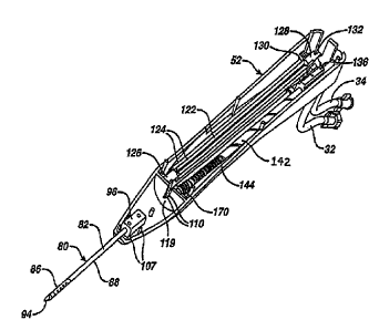
cam
follower pin 152 in variable pitch thread groove 144. The translation of cam
nut
136 along translation shaft 142 continues in step 412.
[0088] At step 414, a predetermined time value stored in a reprogrammable
memory in
control unit 24 is read and compared to an accumulated time count stored in a
temporary memory. The reprogrammable memory may be, for example, a
"flash" memory that is contained in a microcontroller such as, for example, a
PIC18F452 manufactured by Microchip Corporation. The predetermined time
value corresponds to a designated position in the cutter translation path. The
accumulated time count in temporary memory is updated by the microcontroller
at approximately equal time intervals. In one embodiment, the time intervals
can
be less than or equal to about 100 milliseconds, more particularly less than
or
equal to about 50 milliseconds, and in one embodiment about 25 ms. The time
count is derived from the actual time cutter 104 is translating through the
relative
CA 02877504 2015-01-13
-29-
positions one through four, plus (or minus) the time period calculated from a
motor voltage comparison that will be described in more detail below. When the
time count in temporary memory matches the predetermined time value, cutter
104 is deemed to be at position two. If the temporary time count does not
match
the predetermined time value for position two, then cutter 104 is not deemed
to
be at position two, and the operation proceeds to step 416.
[0089] At step 416, the present translation current is read from translation
motor 188.
At step 418, the present translation current reading is compared against a
predetermined current limit stored in the flash memory. If the current reading
is
greater than the predetermined current limit, an error condition is determined
to
exist. The operation of translation motor 188 is stopped, and an error message
is
reported on a user interface at step 420. If at step 418 the present
translation
current reading is equal to or below the predetermined current limit, the
control
method proceeds to step 422.
[0090] At step 422, the present translation current reading is compared with a
predetermined current value stored in a reprogrammable memory referred to
hereinafter as the "current LUT" (Look-Up-Table). The current LUT comprises
a representative current profile for each of the motors 186, 188. The current
profile is derived from experimental and empirical data related to motor
operation and drive current. The current profile is segmented into time
intervals
corresponding to the time intervals of the microprocessor, which in the
exemplary embodiment described herein is 25ms. The location in the current
LUT of the predetermined current value to be used in the comparison is
dependent upon the accumulated time count value at the time of the comparison.
FIG. 25 illustrates an exemplary motor current profile 260 as cutter 104
traverses
a complete cycle from position one to position four, and then back again to
CA 02877504 2015-01-13
-30-
position one. In FIG. 25, current profile 260 is shown as motor current
(vertical
axis) verses time (horizontal axis). As shown by profile 260, the current to
motor
188 varies between time increments and between each of the four cutter
positions. The current LUT comprises the current level of profile 260 at each
segmented time interval.
L0091] In addition to the current measurement, at step 422 the voltage of
translation
motor 188 is read during the off-cycle of the PWM motor drive signal. This
voltage is proportional to the back electromechanical force of motor 188, as
well
as the linear travel speed of cutter 104. From the voltage reading, the actual
position of cam nut 136 along the travel path and, thus, the position of
cutter 104
can be determined. The voltage reading from motor 188 may be compared to the
motor specifications, or a predetermined operational profile, to determine the
actual travel speed from the voltage reading. If the motor voltage reading at
the
accumulated time count exceeds the anticipated voltage for the time count,
then
cutter 104 is deemed to be at a more advanced position in the current profile
than
that anticipated for the accumulated time count. Accordingly, the position of
the
pointer in the current LUT may be adjusted to account for the difference in
distance by increasing the accumulated time count, and thereby retarding the
total advance time for the cutter. Likewise, if the motor voltage reading is
less
than the predetermined level for the accumulated time count, then the cutter
is
deemed to have not traveled as far along the current profile as anticipated by
the
accumulated time count. The position of the pointer in the current LUT may
therefore be adjusted to account for the difference in travel distance by
reducing
the accumulated time count and, therefore, rereading or moving backwards in
the
current LUT and increasing the total advance time for the cutter.
CA 02877504 2015-01-13
-31-
[0092] At step 424, a comparison is made to determine if the difference
between the
present translation current and the current value from the current LUT is
outside
a predetermined range, such as the range indicated by dashed line 262 in FIG.
25.
If the difference between the current values is outside the predetermined
range,
the current to translation motor 188 is adjusted at step 426, such as by
increasing
or decreasing the duty cycle of the pulse width modulated motor control signal
(or by changing a voltage level if an analog motor drive is employed rather
than
PWM). If the difference between the present translation current and the
predetermined current LUT value is determined at step 424 to be within the
acceptable range, then the process returns to step 412 and cutter 104
continues
translating from position one to position two.
[0093] If at step 414 cutter 104 is deemed to be at position two, then the
control method
passes to step 428 shown in FIG. 24B, and the cutter continues translating
from
position two to position three. At step 430, a check is made to determine if
cutter
104 has reached a predetermined intermediate position between position two and
position three. Cutter 104 is deemed to have reached the intermediate position
when the accumulated time count in temporary memory matches a predetermined
time count corresponding to the intermediate position. The predetermined
intermediate position is based on the actual cutter translation speed and the
predetermined cutter rotation speed. The intermediate position is selected to
allow a sufficient amount of time for cutter 104 to accelerate from zero to
the
predetermined rotation speed before cutter 104 has reached position three,
after
which tissue cutting begins. If at step 430 cutter 104 has not reached the
intermediate position, then the present translation current from motor 188 is
read
at step 432.
CA 02877504 2015-01-13
-32-
[0094] At step 434, the present translation current is again compared to a
predetermined
current limit stored in the flash memory. If the present translation current
reading is greater than the predetermined current limit, an error condition is
determined to exist. The operation of translation motor 188 is stopped, and an
error message is reported on a user interface at step 436. If at step 434 the
present translation current is determined to be equal to or below the
predetermined current limit, operation of instrument 20 continues at step 438.
At
step 438, the present translation motor current reading is again compared with
a
predetermined value in the current LUT. Once again, the location of the
comparison value in the current LUT is dependent upon the updated accumulated
time count at the time of the comparison. Also, at step 438 the present motor
voltage is read and compared with the anticipated voltage based upon the
updated accumulated time count. If the actual voltage reading differs from the
anticipated voltage, then the accumulated time count is increased or decreased
to
synchronize the current LUT position with the actual position of the cutter.
If at
step 440 the difference between the present and predetermined current values
is
outside a predetermined range, the current to translation motor 188 is
adjusted at
step 442. If the difference from the comparison at step 440 is within the
predetermined range, then cutter 104 continues translating from position two
to
position three at its present rate at step 428.
[0095] If at step 430 cutter 104 is determined to have reached the
intermediate point
between position two and position three, then the cutter continues to
translate
towards position three and the rotation of the cutter is started at step 444
shown
in FIG. 24C. At step 446, the present rotation current is read for rotary
drive
motor 186. At step 448, a comparison is made to determine if the present
rotation motor current is greater than a predetermined current limit stored in
the
flash memory. If the present current reading is greater than the predetermined
CA 02877504 2015-01-13
-33-
limit, then the rotation and translation motors 186, 188 are stopped at step
460,
and an error condition is reported on the user interface. If the present
rotation
current reading is equal to or below the predetermined limit, then the
operation
continues to the next step. At step 450, the present rotation current reading
is
compared with a predetermined current value loaded into the current uff. As
mentioned above, the location of the comparison value in the current LUT is
dependent upon the accumulated time count at the time of the comparison. If at
step 452 the difference of the comparison is determined to be outside a
predetermined range, the current to the rotation motor 186 is adjusted at step
454.
If at step 452 the difference between the present current value and the
predetermined current value is within a predetermined range, then rotation of
cutter 104 continues.
[0096] At step 456, a predetermined time value stored in memory in the
microcontroller
is compared to the accumulated time count stored in the temporary memory. The
accumulated time count is derived from the actual time the cutter is moving
through its relative position plus (or minus) the time calculated from the
motor
voltage comparisons at steps 422, 438 and 464. When the accumulated time
count matches the stored time count, cutter 104 is determined to be at the
third
position. If cutter 104 is not at the third position, the process continues to
step
458, where the present translation current is read from motor 188. At step
462,
the present translation current reading is compared against a predetermined
current limit. If the present current reading is greater than the
predetermined
limit, the translation and rotation motors are stopped and an error is
reported at
step 460.
[0097] If the reading is equal to or below the limit, the process continues at
step 464,
where the present current reading is compared with a predetermined value
loaded
CA 02877504 2015-01-13
-34-
into the current LUT. The location of the comparison value in the current LUT
is
dependent on the updated accumulated time count at the time of the comparison.
Also, at step 464 the actual motor voltage is compared with the anticipated
voltage. The accumulated time count is increased or decreased as described
above to account for an increase or decrease in the motor voltage
corresponding
to a change in the actual travel speed of cutter 104. If at step 466 the
difference
between the present current reading and the predetermined current value from
the
current LUT is determined to be within an allowable range, then translation of
cutter 104 continues, and the process proceeds to step 446. If the difference
from
the comparison is outside the predetermined allowable range, then the current
to
translation motor 468 is adjusted. After this adjustment, the process
continues to
step 446.
[0098] When it has been determined at step 456 that cutter 104 has reached
position
three, then the process proceeds to step 470 shown in FIG. 24D. At step 470,
the
translation current to motor 188 is changed to a predetermined value and
stored
in the memory. The changed current value continues the translation of cutter
104
towards the fourth position, but at a different velocity, typically 0.5 inches
per
second. At step 472, a predetermined value stored in the reprograminable
memory in the microcontroller is compared to the accumulated time count stored
in the temporary memory. The time count is derived from the actual time cutter
104 is moving through its relative positions plus (or minus) the time
calculated
from the motor voltage comparisons. When the present time count matches the
stored time count, it is deemed that the cutter is at position four.
[0099] At step 474, the present translation current is read. At step 476, the
translation
current reading is compared against a predetermined current limit. If the
translation current reading is greater than the predetermined limit, the
process
CA 02877504 2015-01-13
. ,
'
-35-
moves to step 482, where the translation and rotation motors 186, 188 are
stopped and an error message is displayed. If at step 476 the present
translation
current reading is less than or equal to the limit, the process continues to
step
478. At step 478, the motor voltage is read and compared to a predetermined
motor voltage level. If the voltage reading is higher than anticipated, then
the
accumulated time count is increased to account for an increase in travel
speed. If
the voltage reading is lower than anticipated, the accumulated time count is
decreased to account for a decrease in the actual travel speed of the cutter.
Also
at step 478, the present translation current reading is compared with a
predetermined value loaded into the current LUT. If at step 480 the difference
between the present and predetermined current values is determined to be
outside
of a predefined range, the current is adjusted to the translation motor 186 at
step
484. If at step 480 the difference between the present and predetermined
current
values is within a predetermined range, then cutter 104 continues translating
and
the process moves to step 486. At step 486, the present rotation current is
again
read, and at step 488 the latest current reading is compared against a
predetermined limit. If the current reading is greater than the predetermined
limit, translation and rotation motors 186, 188 are stopped and an error
reported
at step 482. If the present rotation current reading is equal to or below the
predetermined limit, then operation continues on to the next step. At step
490,
the present rotation motor current is again compared with a predetermined
value
loaded into the current LUT, and the difference between the two levels is
calculated. If the difference in the current levels is determined at step 492
to be
outside a predetermined range, then the current is adjusted to the rotation
motor
at step 494. If at step 492 the difference between the two current levels is
determined to be within a predetermined range, then cutter rotation continues,
and the process moves to step 472.
CA 02877504 2015-01-13
- 36 -
[00100] If at step 472, cutter 104 has reached position four, then the control
method
continues to step 496 shown in FIG. 24E, at which point translation motor 188
is stopped. Next, at step 498, a predetermined value stored in the
microcontroller is compared to the accumulated time count stored in the
temporary memory. The time count is derived from the actual time the rotation
motor was turned on plus (or minus) time adjustments calculated from the
motor voltage comparisons. If at step 498 the time count comparison does not
match the stored time count, then the actual rotation motor current is read at
step 500. At step 502, the actual rotation motor current is compared with a
predeteimined value loaded into the current LUT, with the location of the
comparison value in the current LUT being dependent on the time count
interval value at the time of the comparison. If it is determined at step 504
that
the difference between the actual rotation motor current and the
predetelinined
value for the rotation current is outside a predetermined range, then the
current
to rotation motor 186 is adjusted at step 506. If the difference from the
comparison is within the predetermined range, then the control method
proceeds to step 498. At step 498, the predetermined time count is compared to
the accumulated time count for rotation motor 186. If the accumulated time
count exceeds the predetermined value, then the rotation motor is stopped at
step 508.
[00101] While electric motors are disclosed in the embodiments described
above, it will
be understood that other types of motors, such as pneumatic motors could be
employed. Additionally, while an outer cannula with an inner cutter is
disclosed, other variations may be employed, such as an embodiment wherein a
cutter is coaxially disposed about the outside of a cannula.