Note: Descriptions are shown in the official language in which they were submitted.
CA 02877520 2014-12-11
WO 2013/185243
PCT/CA2013/050461
METHOD AND SYSTEM FOR SEPARATION OF SUSPENSIONS
CROSS REFERENCE TO RELATED APPLICATIONS
This application claims the benefit of priority of U.S. Provisional Patent
Application No. 61/660,058, filed June 15, 2012, which is incorporated herein
by
reference in its entirety.
FIELD
The present disclosure relates generally to treatment of a suspension of
solids in a
liquid. More particularly, the present disclosure relates to separation of
tailings or other
wastewater suspensions into solid and fluid components.
BACKGROUND
Mineable oil sands ore comprise bitumen, water, sand, fine clays, and silt.
The
bitumen may be separated from the remaining components of the oil sands using
a hot
water extraction process. In the hot water process, ore is mixed with hot
water, and the oil
floats to the top of the mixture. The water, sand, and silt are present below
the oil. A
caustic solution may be added to facilitate separation of bitumen from the
sand. The oil is
removed from the top of the mixture. The water, including clays and other
fines from the
ore which remain suspended in the water, is removed from the bottom of the
mixture
along with some remaining bitumen, and transported to settling ponds.
Horizontal
separators may have application in separating water from clay and other fines.
An
example of a horizontal separator is found in US patent 2,622,794, issued Dec.
23, 1952 to
Smith.
Fines in suspension settle to about 30 to 40 % solid (w/w), at which point
they
form a gel-like material (a "colloidal suspension"; see below). The colloidal
suspension
includes large amounts of water and slows further settling from the water. In
terms of
weight, the smallest fines may represent about 3% of the mature fine tailings
("MFT"),
but may entrap coarser solids such that the colloidal suspension forming from
MFT may
contain 30% by weight solids.
Water in the MFT cannot immediately be used again in the hot water extraction
process, requiring that additional water be introduced into the system to
continue the hot
- 1 -
CA 02877520 2014-12-11
WO 2013/185243
PCT/CA2013/050461
water process. MFT eventually settle in the ponds producing water that can be
reused, but
the residence time in the ponds can be years, requiring very large settling
ponds which
present a hazard to migrating water fowl and are a potential source of
groundwater
contamination (Mercier et al., 2008).
Clays
Clays are sheet-like phyllosilicate crystalline minerals with a layered
structure of
shared octahedral and tetrahedral sheets. Illite, kaolinite, and
montmorillonite are three
types of clays found in oil sands. Substitution of cations within the
structure of these clays
produces a variety of species of clays (Juma, 1998; Mercier et al., 2008)
Bulk deposits of clay are often present in the oil sands deposits. While bulk
deposits of clay are largely avoided in the mining operations, clay is
distributed in the ore
and is therefore present in the hot water process. Fine clay particles
interfere with the hot
water process and the presence of fines in process water is undesirable.
Particles of clays
have negatively charged surfaces and sheet faces, and positive charges on the
edge
surfaces. Since the surface area of the sheet face is much larger than the
surface area of the
edge face, the negative charges dominate interactions between particles.
Cations, including
H30 , may facilitate binding between sheets of clay. Clays may be non-
swelling, for
example kaolinite and illite clays, or swelling, for example montmorillonite
clays.
Colloidal suspension
When clays are introduced into the hot water process, they become defoliated
and
create the fines found in tailings. The charged surfaces of the fines form
hydrogen bonds
with water molecules. Fines in solution are a colloidal suspension. As the
fines settle,
they reach a point where steric forces impede further settling. When this
point is reached,
the suspension has the consistency of a gel and is called a "floc". Colloidal
suspensions
may be described in terms of Gibbs free energy:
AG = AH - TAS [Eq. 11
In Eq. 1, AG is the change in Gibbs free energy, AH is the change in enthalpy,
AS
is the change in entropy, and T is the temperature, of the system. While
systems seek a
global minimum in G, a system may remain in a local minimum absent sufficient
activation energy ("Ea") to exceed the local minimum G and reach the lower
global
minimum. A floc is at a local minimum and will eventually settle out into
clays which
- 2 -
CA 02877520 2014-12-11
WO 2013/185243
PCT/CA2013/050461
represent a global minimum free energy state. Colloidal suspensions are very
stable and
can last for years.
Bringing defoliated sheets of clay together again is analogous to adsorption
of a
molecule on a surface of another substance. At distance, the adsorbing
molecule may not
be attracted by the surface, and may actually be repelled. However, in close
proximity,
attractive Van der Waal forces may cause adsorption onto the surface.
Similarly, the
negatively-charged surfaces of clay sheets introduce steric repulsive forces
when the fines
particles are at distance, stabilizing the local minimum of the colloidal
suspension.
However, at close distances, the Van der Waal forces may become large enough
to bring
the sheets together. High ionic strength solutions tend to stabilize the
settled clay and
promote the settling of the floc state into the clay state.
The stability of the colloidal suspensions (and the AG value associated with
its
refoliation) is dependent on the AH of hydration of the clay sheets, the AH of
refoliation
into clays, and the AS of the system. Since the clays settle eventually, the
AH of
refoliation is sufficiently negative to overcome the negative AS of the
transition from
colloidal suspension to clay the AH of hydration. To move the equilibrium
towards
formation of ordered sheets (i.e. foliation), energy must be introduced to
overcome the Ea
of the transition. However, introduction of too much energy may move the
colloidal
suspension into an even higher free energy state, which is undesirable.
Fines are negatively charged and their surface area may be upwards of 100
m2/g,
resulting in a high net negative charge of a suspension of fines. Following
use in the hot
water process, water includes OH-. The dissolved OH- contributes to charge
interactions
and interferes with the settling of colloidal suspensions into clays. Each
clay sheet in the
colloidal suspension interacts with water through hydrogen and Van der Waal
bonds,
dissipating surface charge energy. The energy of hydration of the colloidal
suspension
may, along with the steric forces, contribute to the activation energies to be
overcome in
refoliation.
Kaolinite may have a lower Ea to reform into clay than illite. Increasing the
availability of cations to the clay formation may contribute to overcoming the
Ea required
to settle the colloidal suspensions. The availability of cations may be
increased by
acidifying the solution. At lower pH values, cations other than H30+ are less
likely to
remain coordinated to OH- in solution and would be available for binding to
negatively
- 3 -
CA 02877520 2014-12-11
WO 2013/185243
PCT/CA2013/050461
charged surfaces particles of fines. Further, the presence of H30+ may
decrease the
amount of water surrounding fines, allowing particles of fines to settle
closer together (a
hydration layer does not need to be as thick to dissipate the negativity
charge surfaces with
the positive charge on the hydronium ions). This change in environment may
reduce the Ea
enough for the spontaneous settling of the colloidal suspension. If not,
sufficient energy
can be added to the system to overcome the remaining Ea, allowing settling to
occur
spontaneously into the lower free energy state. However, fines in general, and
particularly
fines that have formed a colloidal suspension, do not settle out of solution
easily.
SUMMARY
It is an object of the present disclosure to obviate or mitigate at least one
disadvantage of previous tailings treatment processes.
The method includes separation of fines from tailings in a centrifuge having a
substantially vertical axis of rotation, as described below in this summary,
resulting in an
upper flow stream and a lower flow stream. In some embodiments, the tailings
may be
acidified, a second centrifuge having a substantially horizontal axis of
rotation (as
described below in this summary) may be applied to separate suspended
particles from
water in the lower flow stream, a third centrifuge having a substantially
vertical axis of
rotation may be employed in a step intermediate the other two centrifuges to
treat the
upper flow stream with the upper flow stream being alkalinized prior to being
provided to
the third centrifuge to facilitate formation of ooids from suspended particles
(the ooids
separate more easily from the suspension than fines), or a combination of
these features
may be provided.
A first centrifuge for use in the method includes an inner assembly within a
body.
The inner assembly is separated from an inner surface of the body by a space
and the
interior of the inner assembly is isolated from the space. The inner assembly
includes
paddles and a baffle attached to a drive shaft. The drive shaft is rotatable
about a
substantially vertical axis to rotate the inner assembly. During rotation of
the inner
assembly, centripetal forces force particles to remain in the space, as
opposed to moving
through the baffle into the inner assembly. In addition, frictional forces
between the inner
assembly and the fluid suspension in the discharge space causes the fluids to
rotate with
lower velocity and further urges the particles against the inner wall of the
body (i.e. within
- 4 -
CA 02877520 2014-12-11
WO 2013/185243
PCT/CA2013/050461
the discharge space and not into the inner assembly, similarly in principle to
a cyclone
separator). In the space, the concentrated particles will settle out to the
bottom of the body
for removal as a lower flow stream. Fluid components of a suspension being
centrifuged
within the body may flow into the inner assembly through the baffle. Flowing
through the
baffle dampens turbulent flow into laminar unidirectional flow. The paddles
keep the
fluid moving at the same angular velocity throughout the interior of the inner
assembly.
The fluid can be recovered as an upper flow stream from within the inner
assembly. Thus,
by application of centripetal force and of gravity, most of the particles in
suspension are
sequestered in the space while fluid with a small amount of particles (e.g.
the smallest
particles) flows into the inner assembly. Feed can be continually introduced
into the
discharge space and mixed with the rotating suspension by the turbulent flow
in the
discharge space. The upper and lower flow streams may similarly be removed in
a
continuous process.
A second centrifuge for use in the method includes a body extending along a
substantially horizontal axis. A drive shaft extends through the body and is
connected to a
rake which is positioned proximate an inner surface of the body. The body is
rotatable
independently of the drive shaft. When the drive shaft is rotated at a
differential speed
relative to the body, the rake moves settled solids towards a solids outlet,
while fluid
separated from the solids flow towards a fluid outlet. The rake is centralized
within the
body during rotation by fluid dynamics. As with the first centrifuge, feed can
be added to,
and fluids and solids recovered from, the second centrifuge in a continuous
process.
In a first aspect, the present disclosure provides a method and system for
separating a suspension into solid and fluid components. The suspension is
centrifuged
about a substantially vertical axis of rotation to concentrate solid
components in a first
lower flow stream and fluid components in a first upper flow stream. The first
upper flow
stream may be centrifuged about a substantially vertical axis of rotation to
concentrate
solid components in a second lower flow stream and fluid components in a
second upper
flow stream. The first lower flow stream, the second lower flow stream, or
both, may be
centrifuged about a substantially horizontal axis of rotation to separate
water from
stackable dry tailings. The method and system may be applied to separation of
tailings or
other suspensions.
- 5 -
CA 02877520 2014-12-11
WO 2013/185243
PCT/CA2013/050461
In a further aspect, the present disclosure provides a method of separating
fines
from tailings including providing tailings; and centrifuging the tailings
about a
substantially vertical axis of rotation to separate the tailings into a first
upper flow stream
comprising water and ultrafines, and a first lower flow stream comprising
water and fines.
In an embodiment, the method include separating the first lower flow stream
into
water and stackable product. In an embodiment, separating the first lower flow
stream
into water and stackable product includes centrifuging the first lower flow
stream about a
substantially horizontal axis of rotation. In an embodiment, centrifuging the
first lower
flow stream is with a centripetal force of between 70 G and 170 G at a maximum
centrifugal radius. In an embodiment, centrifuging the first lower flow stream
is with a
centripetal force of about 120 G at a maximum centrifugal radius.
In an embodiment, centrifuging the tailings is with a centripetal force of
between
100 G and 700 G at a maximum centrifugal radius. In an embodiment,
centrifuging the
tailings is with a centripetal force of about 400 G at a maximum centrifugal
radius.
In an embodiment, the method includes acidifying the tailings prior to
centrifuging.
In an embodiment, acidifying the tailings is with CO2. In an embodiment, the
CO2 is at a
pressure of between 7 and 13 MPa. In an embodiment, the CO2 is at a pressure
of about
10 MPa. In an embodiment, the CO2 is at a pressure of between 2 and 8 MPa. In
an
embodiment, the CO2 is at a pressure of about 5 MPa. In an embodiment,
centrifuging the
tailings is in the presence of saturating concentrations of CO2.
In an embodiment, the method includes acidifying the tailings prior to
centrifuging.
In an embodiment, acidifying the tailings is with CO2. In an embodiment, the
method
further rincludes degassing the first upper flow stream to produce CO2 offgas.
In an
embodiment, the degassing is at a pressure of between 2 and 8 MPa. In an
embodiment,
the degassing is at a pressure of about 5 MPa. In an embodiment, method
further includes
recovering and sequestering the CO2 offgas.
In an embodiment, the method includes acidifying the tailings prior to
centrifuging.
In an embodiment, acidifying the tailings is with CO2. In an embodiment, the
method
includes centrifuging the first upper flow stream about a substantially
vertical axis of
rotation to separate the first upper flow stream into a second upper flow
stream comprising
water and a second lower flow stream comprising water and aggregated
ultrafines. In an
embodiment, the method includes alkalinizing the first upper flow stream. In
an
- 6 -
CA 02877520 2014-12-11
WO 2013/185243
PCT/CA2013/050461
embodiment, the first upper flow stream is alkalinized with Ca(OH)2 and OH-.
In an
embodiment, the method includes adding a material to facilitate nucleation of
the fines and
formation of ooids. In an embodiment, the material includes clay, quartz,
carbonate, or a
combination thereof
In an embodiment, the method includes acidifying the tailings prior to
centrifuging.
In an embodiment, acidifying the tailings is with CO2. In an embodiment, the
method
includes centrifuging the first upper flow stream about a substantially
vertical axis of
rotation to separate the first upper flow stream into a second upper flow
stream comprising
water and a second lower flow stream comprising water and aggregated
ultrafines. In an
embodiment, the method includes degassing the second upper flow stream to
produce CO2
offgas. In an embodiment, the method includes recovering and sequestering the
CO2
offgas.'
In an embodiment, the method includes acidifying the tailings prior to
centrifuging.
In an embodiment, acidifying the tailings is with CO2. In an embodiment, the
method
includes centrifuging the first upper flow stream about a substantially
vertical axis of
rotation to separate the first upper flow stream into a second upper flow
stream comprising
water and a second lower flow stream comprising water and aggregated
ultrafines. In an
embodiment, the method includes combining the first lower flow stream with the
second
lower flow stream into a combined lower flow stream, and separating the
combined lower
flow stream into water and stackable product. In an embodiment, separating the
combined
lower flow stream into water and stackable product comprises centrifuging the
combined
lower flow stream about a substantially horizontal axis of rotation. In an
embodiment,
providing the tailings, centrifuging the tailings, centrifuging the first
upper flow stream,
and centrifuging the combined lower flow stream about a substantially
horizontal axis of
rotation are performed as a continuous process.
In an embodiment, the tailings comprise TFT, MFT, or both. In an embodiment,
the tailings comprise up to about 50% (w/w) solids. In an embodiment, the
tailings
comprise 30% to 35% (w/w) solids. In an embodiment, the tailings comprise
about 8%
(w/w) solids.
In a further aspect, the present disclosure provides a centrifuge for
separating a
suspension into an upper flow stream and a lower flow stream. The centrifuge
includes an
elongate body extending along a substantially vertical longitudinal axis
between a bottom
- 7 -
CA 02877520 2014-12-11
WO 2013/185243
PCT/CA2013/050461
end and a top end; a drive shaft extending through the body along the
longitudinal axis and
rotatable about the longitudinal axis independently of the body; two or more
paddles
connected to the drive shaft for agitating the suspension during rotation of
the drive shaft,
an outer edge of each of the paddles separated from an inner surface of the
body to define
a space; a baffle connected to the drive shaft, the baffle disposed between
the drive shaft
and the inner surface of the body for dampening turbulence in the suspension
during
centrifugation; an inlet for receiving the suspension into the body; a lower
flow stream
outlet for discharging the lower flow stream proximate the bottom end; and an
upper flow
stream outlet for discharging the upper flow stream proximate the top end.
In an embodiment, the baffle is positioned between the outer edges of the
paddles
and the inner surface of the body. In an embodiment, the baffle is a shroud
enclosing the
paddles and separated from the inner surface of the body to define the space,
the shroud
having a plurality of apertures for allowing fluid to pass through the shroud.
In an
embodiment, the shroud is connected to paddles at the outer edges of the
paddles. In an
embodiment, the apertures are hexagonal in cross section.
In an embodiment, the paddles are connected to the drive shaft by connectors
and
separated from the drive shaft along a portion of the length of each paddle
along the
longitudinal axis.
In an embodiment, the paddles are connected to the drive shaft by a plurality
of
connector plates between the paddles for compartmentalizing spaces between the
paddles
and the connector plates.
In an embodiment, the inlet is located proximate the top end.
In an embodiment, the inlet is located on the top end.
In an embodiment, the lower flow stream outlet is located on the bottom end.
In an embodiment, the upper flow stream outlet is located on the top end.
In an embodiment, the centrifuge includes an upper flow stream passage within
the
drive shaft, and wherein the upper flow stream outlet is in fluid
communication with the
upper flow stream passage. In an embodiment, the centrifuge includes a second
body
extending from the top end, the second body defining an upper flow stream
discharge
space within the second body, and wherein the upper flow stream outlet is in
fluid
communication with the upper flow stream discharge space.
- 8 -
CA 02877520 2014-12-11
WO 2013/185243
PCT/CA2013/050461
In an embodiment, the centrifuge includes a pump for introducing gas into the
body.
In an embodiment, the centrifuge includes a pressure relief valve on the body
for relieving
pressure within the body.
In an embodiment, the centrifuge includes a cyclone separator below the body
for
collecting the lower flow stream.
In an embodiment, the centrifuge includes an additive inlet in the body for
administering fluids or solids other than the suspension into the body.
In a further aspect, the present disclosure provides a centrifuge for
separating a
suspension into a fluid component and a solids component. The centrifuge
includes an
elongate body extending along a substantially horizontal longitudinal axis
between a fluid
discharge end and a solids discharge end, the body rotatable about the
longitudinal axis; a
separation zone defined within the body, the separation zone having a greater
cross-
sectional area at the solids discharge end than at the fluid discharge end; a
rotation driver
for rotating the body about the longitudinal axis; a drive shaft extending
through the body
and rotatable about the longitudinal axis independently of the body; a rake
connected to
the drive shaft and positioned proximate an inner surface of the body; a first
inlet for
receiving the suspension into the separation zone; a fluid discharge outlet
for discharging
fluid proximate the fluid discharge; and a solids discharge outlet for
discharging solids
proximate the solids discharge end. Rotation of the body with the suspension
in the
separation zone causes rotation of the rake and drive shaft. Differential
rotation of the rake
relative to the body directs solids to the solid discharge end.
In an embodiment, the rake is helical and extends along substantially the
entire
length of the body along the longitudinal axis.
In an embodiment, the centrifuge includes a brake for slowing rotation of the
drive
shaft independently of the body to provide differential rotation of the rake
and the body.
In an embodiment, the first feed inlet is located within the drive shaft. In
an
embodiment, the centrifuge includes a second feed inlet within the drive shaft
for
delivering fluid to the separation zone, the first and second feed inlets
delivering feed at
different longitudinal locations along the separation zone.
- 9 -
CA 02877520 2014-12-11
WO 2013/185243
PCT/CA2013/050461
In an embodiment, the centrifuge includes a support plate mounted on the drive
shaft for supporting the body, the support plate including a plurality of
apertures for
allowing fluid to pass through the support plate.
In an embodiment, the rake defines a cavity on an outer surface of the rake
facing
the inner for pooling of the suspension during rotation of the drive shaft. In
an
embodiment, the centrifuge includes flanges extending laterally from the ski
on each side
of the cavity to facilitate rotation of the rake and the drive shaft by
rotation of the body
with the suspension in the separation zone and to facilitate hydroplaning over
the inner
surface of the body during differential rotation.
In an embodiment, the rotation driver comprises a support wheel positioned
about
an outer surface of the body for supporting the body during rotation of the
body and a
drive wheel positioned about the outer surface for driving rotation of the
body about the
longitudinal axis.
In an embodiment, the fluid discharge outlet is on the fluid discharge end.
In an embodiment, the solids discharge outlet is on the solids discharge end.
In a further aspect, the present disclosure provides a system for separating
fines
from tailings comprising a first centrifuge as summarized above (substantially
vertical axis
of rotation) and a second centrifuge as summarized above (substantially
horizontal axis of
rotation).
In an embodiment, the system includes a third centrifuge for separating a
suspension into an upper flow stream and a lower flow stream. The third
centrifuge
includes an elongate body extending along a substantially vertical
longitudinal axis
between a bottom end and a top end; a drive shaft extending through the body
along the
longitudinal axis and rotatable about the longitudinal axis independently of
the body; two
or more paddles connected to the drive shaft for agitating the suspension
during rotation of
the drive shaft, an outer edge of each of the paddles separated from an inner
surface of the
body to define a space; a baffle connected to the drive shaft, the baffle
disposed between
the drive shaft and the inner surface of the body for dampening turbulence in
the
suspension during centrifugation; an inlet for receiving the suspension into
the body; a
lower flow stream outlet for discharging the lower flow stream proximate the
bottom end;
an upper flow stream outlet for discharging the upper flow stream proximate
the top end;
and a cyclone separator below the body for collecting the lower flow stream.
The second
- 10 -
CA 02877520 2014-12-11
WO 2013/185243
PCT/CA2013/050461
centrifuge includes an elongate body extending along a substantially
horizontal
longitudinal axis between a fluid discharge end and a solids discharge end,
the body
rotatable about the longitudinal axis; a separation zone defined within the
body, the
separation zone having a greater cross-sectional area at the solids discharge
end than at the
fluid discharge end; a rotation driver for rotating the body about the
longitudinal axis; a
drive shaft extending through the body and rotatable about the longitudinal
axis
independently of the body; a rake connected to the drive shaft and positioned
proximate an
inner surface of the body; a first inlet located within the drive shaft for
receiving the
suspension into the separation zone; a fluid discharge outlet for discharging
fluid
proximate the fluid discharge; a solids discharge outlet for discharging
solids proximate
the solids discharge end; and a second feed inlet within the drive shaft for
delivering fluid
to the separation zone, the first and second feed inlets delivering feed at
different
longitudinal locations along the separation zone. Rotation of the body with
the suspension
in the separation zone causes rotation of the rake and drive shaft.
Differential rotation of
the rake relative to the body directs solids to the solid discharge end. In an
embodiment,
the upper flow stream outlet of the first centrifuge is in fluid communication
with the inlet
of the third centrifuge, the lower flow stream outlet of the first centrifuge
is in fluid
communication with the first inlet of the second centrifuge, and the lower
flow stream
outlet of the third centrifuge is in fluid communication with the second inlet
of the second
centrifuge.
Other aspects and features of the present disclosure will become apparent to
those
ordinarily skilled in the art upon review of the following description of
specific
embodiments in conjunction with the accompanying figures.
BRIEF DESCRIPTION OF THE DRAWINGS
Embodiments of the present disclosure will now be described, by way of example
only, with reference to the attached figures.
Fig. 1 is a schematic of a process for separating fines from tailings;
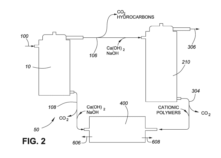
Fig. 2 is a schematic of a system for separating fines from tailings;
Fig. 3 is a partial cutaway perspective view of a centrifuge with a
substantially
vertical axis of rotation;
- 11 -
CA 02877520 2014-12-11
WO 2013/185243
PCT/CA2013/050461
Fig. 4 is a partial cutaway perspective view of an inner assembly of the
centrifuge
of Fig. 3;
Fig. 5 is a cross-sectional elevation view of the centrifuge of Fig. 3 along
the plane
5-5;
Fig. 6 is a cross-sectional plan view of the stage centrifuge of Fig. 3 along
the
plane 6-6;
Fig. 7 is a cross-sectional elevation view of the centrifuge of Fig. 3 along
the plane
5-5 in operation;
Fig. 8 is a cross-sectional plan view of the centrifuge of Fig. 3 along the
plane 6-6
in operation;
Fig. 9 is a partial cutaway perspective view of an alternative inner assembly
for the
centrifuge of Fig. 3;
Fig. 10 is a cross-sectional plan view of the alternative inner assembly of
Fig. 9
along the plane 10-10;
Fig. 11 is a detail view of a permeable sheet with hexagonal apertures for use
with
an inner assembly (e.g. of Figs. 4 or 9);
Fig. 12 is an elevation partial cutaway view of an alternative centrifuge with
a
substantially vertical axis of rotation;
Fig. 13 is a cross-sectional elevation view of an alternative centrifuge with
a
substantially vertical axis of rotation in operation along a plane
corresponding to 5-5 of
Fig. 3;
Fig. 14 is a plan view of a base of the centrifuge of Fig. 13;
Fig. 15 is a perspective view of a centrifuge with a substantially horizontal
axis of
rotation;
Fig. 16 is a cross-sectional elevation view of the centrifuge of Fig. 15 along
the
plane 16-16;
Fig. 17 is a cross-sectional elevation view of the centrifuge of Fig. 15 along
the
plane 17-17 showing a rake assembly and drive shaft without cross section;
Fig. 18 is a cross-sectional elevation view of the centrifuge of Fig. 15 along
the
plane 17-17 showing the rake assembly and drive shaft in cross section;
Fig. 19 is a cross-sectional elevation view of the centrifuge of Fig. 15 along
the
plane 17-17 showing the rake assembly and drive shaft in cross section in
operation;
- 12 -
CA 02877520 2014-12-11
WO 2013/185243
PCT/CA2013/050461
Fig. 20 is a cross-sectional elevation view of an embodiment of a rake of the
centrifuge of claim 15;
Fig. 21 is a cross-sectional elevation view of an alternative centrifuge with
a
substantially horizontal axis of rotation along a plane analogous to the plane
17-17 of Fig.
15 showing a rake assembly and drive shaft without cross section;
Fig. 22 is a cross-sectional elevation view of the centrifuge of Fig. 21 along
a plane
analogous to the plane 17-17 of Fig. 15 showing the rake assembly and drive
shaft in cross
section; and
Fig. 23 is a perspective view of an outer shroud for the centrifuge of Fig.
15.
DETAILED DESCRIPTION
It is desirable to provide an apparatus and process for separating solid
components
from fluid components of tailings. Generally, the present disclosure relates
to a process
and system for separating a suspension of fines into solid and fluid
components (the
suspension exemplified as tailings). The process includes, and the system
facilitates,
centrifuging the suspension about a substantially vertical axis of rotation to
concentrate
solid components in a first lower flow stream and fluid components in a first
upper flow
stream. The first upper flow stream may be centrifuged about a substantially
vertical axis
of rotation to concentrate solid components in a second lower flow stream and
fluid
components in a second upper flow stream. The first lower flow stream, the
second lower
flow stream, or both, may be centrifuged about a substantially horizontal axis
of rotation
to separate water from stackable dry tailings.
The method and system may be applied to separation of tailings or other
wastewater. Tailings are a by-product of many operations, for example mining
operations.
Tailings include at least a fluid component and a solid component. Prior to
application of
the process, sand may be removed from the tailings, for example by use of
tailings
beaches, resulting in suspended tailings including thin fine tailings ("TFT"),
mature fine
tailings ("MFT"), or both. TFT and MFT are suspensions of fines in water.
Generally,
the fines include particles of less than about 40 p.m in their largest
dimension. TFT
include suspensions that are between 5 and 10 percent (w/w) suspended solids,
for
example about 8 percent (w/w) suspended solids. MFT include suspensions that
are up to
about 50 percent (w/w) suspended solids, for example between 30 and 35 percent
(w/w)
- 13 -
CA 02877520 2014-12-11
WO 2013/185243
PCT/CA2013/050461
suspended solids, and may form colloidal suspensions. The process has
application to
tailings from mining operations, for example TFT and MFT from oil sands
mining.
Alternatively, the process may be applied to separation of solid and fluid
components of
other colloidal suspensions in other industries. In a further alternative, the
process may be
applied, for example, to separation of two fluids of varying density, for
example water
separated from bitumen swollen with CO2, or separation of fluids from solids
in treatment
of sewage or other wastewater.
Tailings may include ultrafines (particles less than about 3 p.m in diameter).
In the
settling ponds, the coarse sand and larger silt particles quickly settle out.
The clays and
other fines settle out over time, sometimes over a period of seven years or
more.
Ultrafines in the tailings lead to increased settling times in part because of
steric forces
between the particles, particle clusters, and ions in solution.
The process employs centrifugation to separate fines from the fluid components
of
tailings. The process may also employ acidification of the tailings, for
example with CO2,
to increase the cation availability and to increase the ionic strength of the
water. The
resulting solid component may be stackable (Mikula et al., 2008).
Energy may be added to a colloidal suspension to overcome the Ea for the
transition from the colloidal suspension to a settled product, accelerating
the settling
process (e.g. by centrifuging the suspension). Alternatively, the environment
of the
colloidal suspension can be changed to reduce the required Ea (e.g. by
acidifying clay
particles). Each of these mechanisms of accelerating settling of the colloidal
suspension
may be applied in the process.
Centrifuge Theory
Centrifuges generate centripetal acceleration by rotating at high speeds. The
magnitude of the centripetal acceleration is given by
a =2r [Eq. 21
In Eq. 2, r is the radius of a body being spun and co is rotational velocity.
Dense particles in suspension experience three forces, which at steady state
sum to
zero. The first force is the centripetal force ("F") due to centripetal
acceleration generated
by the centrifuge:
F = ma [Eq. 31
In Eq. 3, m is the mass of the particle.
- 14 -
CA 02877520 2014-12-11
WO 2013/185243
PCT/CA2013/050461
The second force is the buoyant force ("Fab"), which is force on the particle
equivalent to that of the displaced water resulting in net centripetal force
("Fe") on the
particle:
Fr, = Fab = Vp(pp ¨ pw)co2r [Eq. 41
In Eq. 4, Vp is the particle volume, and pp and põ, are the densities of the
particle
and of water, respectively.
The third force is the drag force on the particle, or the force of the fluid
opposing
the velocity of the particle in the parallel directions of the centripetal
force. Where the
particles have a very high aspect ratio (i.e. where the particles are long and
narrow), the
particles are likely to align with flow of fluid within which they are
suspended.
The centrifuge creates pressure as it rotates with the highest pressure at the
outside
given by Eq. 5:
Pr2 = Prl RP(02(r22 - ri2) [Eq. 51
In Eq. 5, Pri is the pressure at the interface of the water at radius r1 and
Pr2 is the
pressure at radius r2, where r2> r1. Where the density of the suspension is
high enough
that the particles contact and can partially support the pressure, pressure
will contribute to
compacting the suspension. At such a density, water is pushed out of the
porosity by
collapsing the solid structure under the pressure Pr2.
Acidifying Tailings With CO2 and CaCO3 Precipitation
Dissolution of CO2 in water occurs by the following reaction:
CO2 + H20 4¨> H+ + HCO3- 4¨> 2H+ + C032
-
When CO2 is dissolved in water at a pressure of approximately 10 MPa, the
resulting solution may have a pH of approximately 3 (Hangx, 2005). CaCO3 in
solution
saturated by CO2 will form soluble Ca(HCO3)2. Lowering the partial pressure of
CO2
results in evolution of CO2 from solution. Evolution of CO2 results in an
increase of the
pH of the solution. Increasing the pH results in precipitation of Ca(HCO3)2.
An increase in ionic concentration increases the strength of ionic
interactions in the
colloidal suspension, neutralizing the steric forces and facilitating
settling, and also
facilitates refoliation of the clay. H30+ facilitates refoliation of the clay
and makes the AH
of hydration of the clay sheets more favorable. H30+ and other cations bind to
the
negatively charged surfaces of the clay sheets. H30+ interacts with the water
about the
- 15 -
CA 02877520 2014-12-11
WO 2013/185243
PCT/CA2013/050461
clay sheets, neutralizing the sheets' negative surface charge, and lowers both
the AH of
hydration of the clay sheets and the Ea for the colloidal suspension to reform
into clay.
CaCO3 precipitates onto negativity charged surfaces, for example those of
quartz
and clays. The large surface area of the fines organized into clay sheets
makes them a
preferred surface upon which precipitation may occur. Addition of Ca(OH)2 to a
solution
of CO2 may result in precipitation of CaCO3 on to the sheets, neutralizing the
net charge
on the surface of the fines and facilitating aggregation of the fines into
larger layers,
further facilitating settling.
The tailings may include bitumen droplets emulsified with water. When exposed
to CO2,
the droplets become less dense and the emulsion with water may break. CO2
dissolves in
bitumen, swelling the volume of the bitumen, for example by approximately 5-
10%,
reducing the density of the bitumen, and reducing the strength of the water-
bitumen
emulsion. In addition, caustic water from extraction of the bitumen often
creates salts
with organic acids in the bitumen. In the acidic environment, these salts
revert to organic
acids, lowering any surfactant tendency of the bitumen. In addition, these
organic acids
may facilitate removal of heavy metal ions from the water.
Process and System
Fig. 1 is a schematic of an embodiment of the process. The process of Fig. 1
has
three stages. At stage one, fines in the tailings are separated from water,
hydrocarbons,
and ultrafines. At stage two, the ultrafines from stage one are precipitated
as ooids
("ooids" are described below) and the water and hydrocarbons from stage one
are
recovered. At stage three, the fines from stage one and the ooids from stage
two are
further dewatered into stackable product, and the resulting water may be
recovered for
reuse.
Fig. 2 is a schematic of an embodiment of a system 50 used to carry out the
process. The system includes a stage one centrifuge 10, a stage two centrifuge
210, and a
stage three centrifuge 400. The roles of each of these components of the
system 50 are
described below according to each of the three steps of the method.
Stage One
Tailings 98 are provided, for example from used process water from which sand
and silt have settled out in a settling pond. The tailings 98 may include TFT
and MFT.
The tailings 98 may be recovered from the settling pond for use as stage one
feed 100. In
- 16 -
CA 02877520 2014-12-11
WO 2013/185243
PCT/CA2013/050461
an embodiment, the tailings 98 may be acidified by exposure to CO2 at
pressure, for
example between 2 and 8 MPa CO2, or at about 5 MPa, prior to use as stage one
feed 100.
Alternatively, CO2 pressure may be between 7 and 13 MPa, or about 10 MPa. The
stage
one feed 100 may be about 95% water by volume, for example between 92% and
98%.
Alternatively, the stage one feed 100 may have a lower percentage of water by
volume, for
example 65% to 70% or about 50%. The remaining components of the stage one
feed 100
include fines (including ultrafines) and may include hydrocarbons.
The stage one feed 100 is separated by centripetal force and gravity. In an
embodiment, a stage one centrifuge 10 (discussed below with reference to Figs.
3 to 12)
may be used, which applies a combination of centripetal force and gravity to
separate a
portion of the fines in the stage one feed 100 from water, hydrocarbons, and
ultrafines in
the stage one feed 100. Without being bound by theory, acidification may
facilitate
settling of fines and separation of the hydrocarbons may be facilitated by CO2
swelling.
The stage one feed 100 is separated into a stage one upper flow stream 106 and
a
stage one lower flow stream 108. The stage one upper flow stream 106 includes
water and
ultrafines. The stage one upper flow stream 106 may include hydrocarbons and
fines. The
stage one lower flow stream 108 includes water and fines. The stage one lower
flow
stream 108 may include hydrocarbons and ultrafines. The concentration of fines
in the
stage one lower flow stream 108 will be greater than in the stage one feed
100. For
example, of the fines present in the stage one feed 100, between about 2%
(w/w) and
about 40% (w/w) may be concentrated in the stage one lower flow stream 108.
For
example, of the ultrafines present in the stage one feed 100, between about 3%
(w/w) and
about 5% (w/w) may be concentrated in the stage one upper flow stream 106. The
percentage may be affected by factors including, for example, the clays in the
stage one
feed 100, the radius of the centrifuge, the speed of rotation, the pH of the
stage one feed
100, and the ionic strength of the stage one feed 100.
The stage one lower flow stream 108 may, for example, have a density of about
1,500 kg/m3, for example between 1,300 kg/m3 and 2,000 kg/m3, and be flowable.
A feed
rate of stage one feed 100 of, for example 15,000 m3/d, may produce 14,250
m3/d of stage
one upper flow stream 106 and 750 m3/d of stage one lower flow stream 108.
In an embodiment, stage one lower flow stream 108 may be added to the stage
one feed
100 to increase the rate of collisions between clay particles and facilitate
aggregation and
- 17 -
CA 02877520 2014-12-11
WO 2013/185243
PCT/CA2013/050461
separation of fines from fluid. Once stage one of the process has reached a
steady state,
further addition of stage one lower flow stream 108 may be unnecessary.
Stage Two
In an embodiment, the process includes stage two. In stage two, ultrafines
suspended in the stage one upper flow stream 106 are precipitated as ooids 300
and are
separated from water present in the stage one upper flow stream 106. The ooids
300 are
spherical structures which precipitate from CaCO3 solutions.
In an embodiment, the stage one upper flow stream 106 may be alkalinized, for
example by addition of Ca(OH)2 and NaOH to the stage one upper flow stream
106. The
resulting increase in pH facilitates formation of ooids 300 including CaCO3.
The ooids
300 may grow from nucleation points on particles of fines. In an embodiment,
addition of
Ca(OH)2 and NaOH raises the pH of the stage one upper flow stream 106 to about
8, for
example between 7.5 and 8.5.
The stage one upper flow stream 106 with Ca(OH)2 and NaOH is separated by
centripetal force and gravity. In an embodiment, a stage two centrifuge 210
(discussed
below with reference to Figs. 13 and 14) may be used, which applies a
combination of
centripetal force and gravity to separate a portion of the ultrafines
(precipitated as ooids
300) in the stage one upper flow stream 106 from water in the stage one upper
flow stream
106.
The stage one upper flow stream 106 with Ca(OH)2 and NaOH is separated into a
stage two upper flow stream 306 and a stage two lower flow stream 304. The
stage two
upper flow stream 306 includes water and may be useful for reuse in a hot
water extraction
process. The stage two lower flow stream 304 includes the ooids 300 that
precipitate from
the stage one upper flow stream 106. During centrifugation, the ooids 300 may
remain
suspended in solution and migrate to the bottom and outside of the centrifuge
as they
increase in size. The longer the ooids 300 are in the suspension, the more the
ooids 300
will grow, increasing the extent to which they will be affected by gravity and
centripetal
force.
In an embodiment, material may be added to provide nucleation points for
formation of ooids 300, resulting in facilitated nucleation of the fines to
form ooids 300.
The material may for example be clay, quartz, or carbonate, and may have a
particle size
- 18 -
CA 02877520 2014-12-11
WO 2013/185243
PCT/CA2013/050461
of, for example, about 40 microns in the largest dimension. A greater surface
area to mass
ratio of the added material will facilitate nucleation.
In an embodiment, the stage one lower flow stream 108 is centrifuged under
pressure. In an embodiment, the pressure is between 2 and 8 MPa CO2, or at
about 5 MPa.
In an embodiment, the pressure is between 7 and 13 MPa, or about 10 MPa.
In an embodiment, the stage one upper flow stream 106 may be degassed prior to
centrifugation, for example at atmospheric pressure, between 2 and 8 MPa
pressure, or at
about 5 MPa pressure, to allow evolution of some CO2 from solution. CO2 vapour
may be
recovered from the stage one upper flow stream 106, for example with a vapour
recovery
unit ("VRU"; not shown). For example, a first tank and a second tank in series
(not
shown), each equipped with a skimmer and a VRU, may be used to recover CO2.
Placement of the stage one upper flow stream 106 into the first and second
tanks
allows the CO2 to evolve from solution in the stage one upper flow stream 106.
Without
being bound by theory, the CO2 may nucleate on some of the ultrafines and
float them to
surface. Hydrocarbons remaining in the stage one upper flow stream 106 may
float to the
top of the stage one upper flow stream 106, which may be facilitated where the
hydrocarbons are swollen with CO2. The skimmer may be used to remove
ultrafines and
hydrocarbons from the surface of the tops flow stream. The hydrocarbons may
include
hydrophobic minerals, for example titanium and zirconium (Majid et al., 2005),
which
may also be recovered. Ca(OH)2 and NaOH may be added in the second tank prior
to
adding the stage one upper flow stream 106 with Ca(OH)2 and NaOH to the stage
two
centrifuge.
Stage Three
In an embodiment, the process includes stage three. In stage three, stage
three feed
is separated into stackable product and water. In an embodiment, the stage
three feed may
be the stage one lower flow stream 108. In an embodiment, the stage three feed
includes a
combination of the stage one lower flow stream 108 and the stage two lower
flow stream
304, and the combined lower flow streams are separated into stackable product
and water.
The water may be reused as process water. The stackable product may be used to
reclaim
mine sites. The stackable product includes aggregated fines and water. The
stackable
product may for example have a density of between 1700 to 2000 kg/m3, for
example
about 1850 kg/m3 (approximately 30% water). Lower water fractions in the
stackable
- 19 -
CA 02877520 2014-12-11
WO 2013/185243
PCT/CA2013/050461
product may be achievable, depending on a number of factors, including the
solid's
porosity (with greater porosity fines retaining more water) and economic
considerations.
In an embodiment, the stage three feed may be separated into stackable product
and water in a stage three centrifuge (discussed below with reference to Figs.
15 to 23).
The stage three centrifuge is elongate with a substantially horizontal axis of
rotation and
includes a rake for skimming an inner surface of the centrifuge to displace
suspended
solids along the axis of rotation.
In an embodiment, the stage one lower flow stream 108 may be degassed to
remove CO2 prior to separation of the stage one lower flow stream 108 into
stackable
product and water. In an embodiment, the stage two lower flow stream 304 may
be
degassed prior to introduction of the stage two lower flow stream 304 into
stackable
product and water. Degassing may be in a tank with a VRU providing atmospheric
pressure or lower.
In an embodiment, Ca(OH)2 and NaOH may be added to the stage one lower flow
stream 108 to precipitate CaCO3. Precipitation of CaCO3 removes additional CO2
from
solution and facilitates aggregation of fines. Without being bound by theory,
the stage two
lower flow stream 304 may increase the pH of the stage one lower flow stream
108 and
cause further precipitation of CaCO3 from the stage one lower flow stream 108.
In an embodiment, cationic polymers may be added to either the stage one flow
stream, the stage two lower flow stream 304, or both, prior to introducing the
lower flow
streams into the stage three centrifuge. Addition of cationic polymers may
facilitate
aggregation and precipitation of the fines. The more CaCO3 that has already
precipitated
from either the stage one lower flow stream 108, the stage two lower flow
stream 304, or
both, the less the benefit of adding cationic polymers.
Stage One Centrifuge
Figs. 3 to 8 show a stage one centrifuge 10. The stage one centrifuge 10
includes a
body 12 with a top 14 and a bottom 16. The inner assembly 18 is within the
body 12. The
inner assembly 18 includes a drive shaft 20 and a plurality of paddles 22
connected to the
drive shaft 20 by connectors 42. The inner assembly 18 is drivingly engaged by
the drive
shaft 20. A discharge space 24 is between an outer edge 26 of the paddles 22
and an inner
surface of the body 12. Bearings 27 are mounted in the body 12 to allow
rotation of the
drive shaft 20. The drive shaft 20 is substantially vertical, and may be
vertical (e.g. in the
- 20 -
CA 02877520 2014-12-11
WO 2013/185243
PCT/CA2013/050461
stage one centrifuge 10). As a result, an axis of rotation about the drive
shaft 20 is
substantially vertical. The extent to which the axis of rotation of the drive
shaft 20 may be
off the vertical and still achieve the performance required for a given
application will
depend on the given application and operating parameters of a given
embodiment. For
example, in some embodiments, the drive shaft 20 may be off the vertical by up
to 10
degrees (e.g. in the stage one centrifuge 210 of Fig. 12 is off the vertical
by about 10
degrees).
The stage one centrifuge 10 includes a baffle for dampening turbulence in the
suspension during centrifugation as fluid components 104 (Figs. 7 and 8) flow
into the
center of the inner assembly 18. The baffle is exemplified in the stage one
centrifuge 10
as a shroud 38 connected to the drive shaft 20, the shroud 38 including a
plurality of
apertures 40 to facilitate flow of fluids through the shroud 38. The paddles
22 are within
the shroud 38, and the discharge space 24 is defined between the shroud 38 and
the inner
surface of the body 12. Other suitable baffles may be employed and located
between the
drive shaft 20 and the inner surface of the body 12. Without being bound by
theory, the
baffle, exemplified by the shroud 38, may decrease turbulence in the
suspension during
centrifugation by increasing the uniformity of fluids passing through the
apertures 40
toward the center of the inner assembly 18, which may decrease the likelihood
that
suspended solids are swept by fluids migrating toward the center of the inner
assembly 18.
The stage one feed 100 flows into the discharge space 24 through a feed inlet
28,
exemplified as being in an outer shell wall 32 of the body 12. A lower flow
stream outlet
for discharging the lower flow stream 108 is proximate the bottom 16. The
lower flow
stream outlet 30 may be in an outer shell wall 32, or may be in the bottom 16
and co-
extensive with at least a portion of the discharge space 24. An upper flow
stream outlet 34
25 for discharging the upper flow stream 106 is proximate the top 14.
In an embodiment, and
as shown in the figures, the upper flow stream outlet 34 may be at least
partially within the
drive shaft 20 to allow the stage one top flow stream to flow out of the upper
flow stream
outlet 34 during rotation of the drive shaft 20.
Operation of Stage One Centrifuge
30 Figs. 7 and
8 show the stage one centrifuge 10 in operation. Stage one feed 100 is
added to the discharge space 24 through the feed inlet 28. The drive shaft 20
is rotated to
generate centripetal forces many hundreds the force of gravity at the outer
edges 26 of the
- 21 -
CA 02877520 2014-12-11
WO 2013/185243
PCT/CA2013/050461
paddles 22. For example, where the stage one centrifuge 10 has a diameter of
1.5 m at the
outer edges 26, rotation at 60 m/s will generate a force of approximately 400
G at the outer
edges 26. Centrifugal forces of, for example, between 100 and 700 G may also
be
effective for separating fines from stage one feed 100. For other
applications, for example
separating hydrocarbons from water, lower centrifugal forces may be effective,
for
example about 200 G. Gravity and centripetal force each contribute to
separating solid
components 102 of the stage one feed 100 from fluid components 104. Gravity
draws the
solid components 102 down. Centripetal force urges the solid components 102
outward.
Centripetal force is greater proximate the outer surface of the inner assembly
18
than at points closer to the drive shaft 20 (e.g. at surface of the shroud 38;
in
emebodimetns where the baffle is located further inward relative to the outer
edges 26 of
the paddles, centripetal force may be greater proximate the outer edges 26
than at points
closer to the drive shaft 20). The greater centripetal force facilitates
separation of solid
components 102 from fluid components 104 of the stage one feed 100 at the
interface
between the shroud 38 and the discharge space 24. Separation of the fluid
components
104 from the solids components 102 occurs primarily at the shroud 38. In
addition, the
greater bulk density of the stage one feed 100 compared to upper flow stream
106
proximate the top 14 may facilitate separation of the fluid components 104
from the solid
components 102 based on differences in bulk density. The fluid components 104
passing
through the apertures 40 in the shroud 38 will include a proportion of the
suspended solids
which do not follow the solid components 102 to the inner surface of the body
12.
Without being bound by theory, the action of the stage one centrifuge 10
concentrates the solid components 102 in the discharge space 24 proximate the
bottom 16,
producing stage one lower flow stream 108, which includes water and solid
components
102. The stage one lower flow stream 108 may be removed from the stage one
centrifuge
10, for example by a worm gear (not shown). The fluid components 104 are
displaced
upward, producing the stage one upper flow stream 106. The stage one upper
flow stream
106 may for example include water, hydrocarbons, and ultrafines. The stage one
upper
flow stream 106 flows out of the stage one centrifuge 10 through the second
upper flow
stream discharge outlet 39.
Without being bound by theory, if the stage one feed 100 has a lowered pH, the
surfaces of
clay sheets may be neutralized by H30 , facilitating aggregation of the fines
and therefore
- 22 -
CA 02877520 2014-12-11
WO 2013/185243
PCT/CA2013/050461
facilitating separation of fines from water, hydrocarbons, and ultrafines.
Clay sheets may
align themselves with the flow, presenting a small aspect ratio to the flow
and lowering
drag force on the fines.
Without being bound by theory, rotation of the inner assembly 18 may transfer
energy to a colloidal suspension in the stage one feed 100 which is fed into
in the
discharge space 24. The energy transferred may be sufficiently high to
overcome the Ea
and break down the colloidal suspension in the discharge space 24,
facilitating flow of
stage one lower flow stream 108 out of the body 12. The energy transferred may
also be
sufficiently low to not cause excessive turbulent flow in the discharge space
24 to impede
settling of the solid components 102.
The shroud 38 may lower the amount of energy transferred from the paddles 22
to
the stage one feed 100. Without being bound by theory, the presence of the
shroud 38
may mitigate erosion of the body 12 by the stage one feed 100 during
centrifugation. In
addition, a boundary effect in the discharge space 24 may reduce the flow near
the inner
surface of the body 12, where the viscosity of the stage one feed 100 due to
the solid
components 102 will be the greatest. The boundary effect thus provides a slow
moving
viscous mud at the inner surface of the body 12 and contributes to lowering
erosion of the
inner surface of the body 12. These effects may be more pronounced in
embodiments
where the inner shell 12 has a smooth inner surface.
The radial dimension of the paddles 22 and the rotational velocity during
operation
determine the drag force on suspended particles in the stage one feed 100.
Without being
bound by theory, the larger the radial dimension of the paddles 22, the higher
the bulk
flow velocity of the water, resulting in the removal of smaller particles. At
a greater radial
dimension of the paddles 22, the pressure generated by the paddles 22 during
operation
increases.
In an embodiment, stage one lower flow stream 108 may be reintroduced into the
discharge space 24 to provide nucleation points for aggregation of fines. The
stage one
lower flow stream 108 may be introduced in the discharge space 24 during
operation or
prior to the stage one feed 100 entering the discharge space 24 through the
feed inlet 28.
During operation of the stage one centrifuge 10, a column 110 of CO2 gas may
form in the center of the inner assembly 18. The pressure at the fluid-0O2
interface 112
may be kept at a selected pressure to provide a selected result, for example
10 MPa to
- 23 -
CA 02877520 2014-12-11
PCT/CA2013/050461
07 July 2014 07-07-2014
keep the concentration of CO2 dissolved in the stage one feed at a selected
value and
maintain a selected pH. The column 110 may be regulated using the relief valve
44.
Without being bound by theory, the column 110 may mitigate the tendency for
fluids
being centrifuged to cause cavitation on the drive shaft 20.
In an embodiment, a level controller (not shown) may detect differential
pressures
between atmospheric and within the centrifuge 10 to regulate the flow out of
the upper
flow stream outlet 34. At a pressure of 10 MPa, the body 12 may be exposed to
pressures
of about 30 MPa during operation as a result of pressure generated by the
paddles.
Pressure generated by the paddles 22 during operation may be reduced by
reducing the
thickness of the water and maximizing the diameter of the column 110, or by
reducing the
rotational speed of the paddles 22.
Design considerations for the stage one centrifuge 10 are influenced by
factors including
the selected daily flow rate of stage one feed 100 into a single stage one
centrifuge 10.
The proportion of stage one feed 100 that will generate stage one upper flow
stream 106
and stage one lower flow stream 108 will be determined by, among other
factors, the
specific stage one feed 100 being treated, and the speed at which the stage
one centrifuge
10 is operated. For example, 15,000 m3/d of stage one feed 10 may added to the
discharge
space 24, and 80% of the stage one feed 100 volume may be stage one upper flow
stream
106 while the remaining 20% of the stage one feed 100 volume may be stage one
lower
flow stream 108. In this example, the rate of flow from the lower flow stream
outlet 30
may be about 3,000 m3/d of stage one lower flow stream 108 that is 50% by
volume water
with a density of 1,500 kg/m3. In contrast, the rate of flow from the upper
flow stream
outlet 34 may be about 12,000 m3/d of the stage one upper flow stream 106 that
is (which
is predominantly water with a small around of fines, ultrafines, and
hydrocarbons). The
rate that the stage one lower flow stream 108 is removed at will have to be
selected to
account for these and other factors.
Alternative Features in the Stage One Centrifuge
In an embodiment, a second body 35 extends from the top 14 to provide an upper
flow stream discharge space 37. An upper flow stream discharge passage 41
provides
fluid communication between the body 12 and the upper flow stream outlet 34.
The upper
flow stream discharge outlet 34 is in fluid communication with the upper flow
stream
discharge space 37. A second upper flow stream discharge outlet 39 provides
fluid
- 24 -
AMENDED SHEET
CA 02877520 2014-12-11
WO 2013/185243
PCT/CA2013/050461
communication between the upper flow stream discharge space 37 and the
exterior of the
stage one centrifuge 10.
In an embodiment, the inner assembly 18 includes an inner assembly top 36 and
an
inner assembly bottom 43. The inner assembly top 36 and inner assembly bottom
43
prevent backflow of stage one upper flow stream 106 into the inner assembly
18. The
inner assembly top 36 and the inner assembly bottom 43 are each wear surfaces
and may
be hardened to withstand abrasion, may be designed to be easily replaced, or
both.
In an embodiment, the shroud 38 may be a smooth material, for example sheet
metal, to
provide a smooth outer surface of the shroud 38. In an embodiment, protrusions
(not
shown) may extend from the inner surface of the body 12 to slow fluid flow
near the inner
surface of the body 12, reducing erosion of the body 12.
In an embodiment, the paddles 22 may have a negatively-charged surface to
facilitate alignment of clay particles with the flow of fluid when the stage
one centrifuge
10 is in operation to reduce drag. For example, the paddles 22 may be exposed
to a
negative charge, or the body 12 may be exposed to a positive charge.
Alternatively, a
suitable coating may be applied to the paddles 22 to provide a negative charge
to the
paddles (for example, a plastic or other material that allows a static
electric charge to be
built up) (Shainberg et al., 1982; Laurent et al., 2006).
In an embodiment, the shroud 38 may have a negatively-charged surface to
facilitate alignment of clay particles with the flow of fluid when the stage
one centrifuge
10 is in operation to reduce drag.
In an embodiment, the connectors 42 may be substantially perpendicular to the
paddles 22.
In an embodiment, the feed inlet 28 may be proximate the top 14. In an
embodiment, the
feed inlet 28 may be in the top 14.
In an embodiment, a plurality of stage one feed inlets 28 may be distributed
along
the length, the periphery, or both, of the body 12. This may decrease
differences in bulk
density of material in the stage one centrifuge.
In an embodiment, the drive shaft 20 may be powered by a variable speed motor
(not shown). The motor may, for example, be an electric motor.
In an embodiment, a pressure relief valve 44 is in the body 12 to relieve
pressure from
within the body.
- 25 -
CA 02877520 2014-12-11
WO 2013/185243
PCT/CA2013/050461
In an embodiment, a pump, for example a metering pump, is present on the stage
one centrifuge 10 to provide CO2 to the stage one feed 100 at a selected
concentration.
For example, the CO2 may be provided at a pressure selected to result in a
partial pressure
of 10 MPa CO2 in the centrifuge. For example, the CO2 may be provided at a
pressure
selected to result in a partial pressure in the centrifuge equal to that of a
column of CO2
gas (for example column 110 in Figs. 7 and 8).
In an embodiment, the stage one centrifuge 10 may include features to control
the
rate of removal of the stage one lower flow stream 108. For example, the lower
flow
stream outlet 30 may include a worm gear (not shown). In an embodiment, the
rate of
removal may be controlled based on a selected density of stage one lower flow
stream 108
in the discharge space 24. For example, removal may begin when the density of
the stage
one lower flow stream 108 is sufficiently great.
Figs. 9 and 10 show an alternative inner assembly 218 for the stage one
centrifuge
10. In the inner assembly 218, the paddles 22 extend to the drive shaft 20
along
substantially their entire longitudinal lengths, in contrast to being
connected to the drive
shaft 20 by connectors 42 as in the inner assembly 18. Disc supports 242 are
present in
place of the connectors 42 and compartmentalize the inner assembly 218.
Without being
bound by theory, compartmentalization of the inner assembly 218 may further
increase the
uniformity of fluids passing toward the center of the inner assembly 218,
which may
further decrease the likelihood that suspended solids 102 are swept by fluids
104 migrating
toward the center of the inner assembly 218.
Fig. 11 shows an alternative shroud 238 having apertures 240 in the shape of
hexagons. A permeable sheet 239 is present at the base of the apertures 240
for allowing
fluids to pass through the shroud 238. In an embodiment, the apertures 240 may
be about
25 mm in depth and about 3 mm between points on the hexagonal cross section of
the
apertures 240.
Fig. 12 shows an alternative centrifuge 250 with a substantially vertical axis
of
rotation that is off the vertical by about 10 degrees.
Stage Two Centrifuge
Fig. 13 is a cross-sectional elevation view of a stage two centrifuge 210 in
operation. Fig. 14 is a plan view of a base 204 of the stage two centrifuge
210. The stage
two centrifuge 210 includes features common to the stage one centrifuge 10. In
addition
- 26 -
CA 02877520 2014-12-11
WO 2013/185243
PCT/CA2013/050461
to the features common to the stage one centrifuge 10, the stage two
centrifuge 210
includes a cyclone separator 202 at the bottom of the stage two centrifuge
210. The drive
shaft 20 and inner assembly 18 are supported on a base 204 anchored to the
body 12 by
legs 206. Rotation of the inner assembly 18 provides a rotating flow to
separate ooids 300
from stage two upper flow stream 306.
In an embodiment, the stage two centrifuge 210 may include a plurality of
additive
inlets 208 along the wall 32 for introducing chemicals to the discharge space
24. For
example, addition of Ca(OH)2 may ensure that fluid in the body 12 (for example
stage one
upper flow stream 106) is saturated with CaCO3.
In an embodiment, the inner surfaces of the stage two centrifuge 210 are
coated
with a material to which CaCO3 is unlikely to bind, for example a non-polar
surface
coating.
In an embodiment, the volume of the discharge space 24 may be selected to
facilitate
formation of ooids 300 (see "Operation of Stage Two Centrifuge", below) by
allowing
the ooids 300 more time to form. A smaller discharge space 24 may facilitate
faster flow
of fluids during centrifugation, greater mixing with turbulence, and more
rapid coating of
fines with CaCO3 to form ooids 300. A larger discharge space 24 may facilitate
greater
resonance time but may also slow flow of fluids during centrifugation, reduce
mixing with
turbulence, and slow coating of fines with CaCO3, impeding formation of ooids
300
(relative to a smaller discharge space 24).
Operation of Stage Two Centrifuge
In operation, stage one upper flow stream 106 is introduced to the discharge
space
24 through the feed inlet 28. The stage one upper flow stream 106 may be
alkalinized, for
example by addition of Ca(OH)2 and OH- (for example as NaOH). In an
embodiment, the
stage one upper flow stream 106 is alkalinized prior to introduction into the
discharge
space 24. In an embodiment, the stage one upper flow stream 106 is alkalinized
following
introduction into the discharge space 24, for example by addition of Ca(OH)2
and OH- at
the inlets 208.
Without being bound by theory, ooids 300 form in the alkalinized stage one
upper
flow stream 106 during operation of the stage two centrifuge 210. The ooids
300 are
drawn down by gravity and urged outward towards the body 12 by centripetal
force. As a
result of the movement of ooids 300, fluid components 302 of the stage one
upper flow
- 27 -
CA 02877520 2014-12-11
WO 2013/185243
PCT/CA2013/050461
stream 106 flow upward. Stage two lower flow stream 304, which includes ooids
300 and
water, is collected by the cyclone separator 202 and flows out of the stage
two centrifuge
210 through the lower flow stream outlet 30. The ooids 300 become more likely
to settle
as they increase in size. The ooids 300 will increase in size where they are
exposed to
CaCO3 at elevated pH. Stage two upper flow stream 306, which includes water,
flows out
of the upper flow stream outlet 34 and second upper flow stream discharge
outlet 39.
Stage Three Centrifuge
Figs. 15 to 19 and 23 show a stage three centrifuge 400. The stage three
centrifuge
400 includes an elongate body 402 having a fluid discharge end 404 and a
solids discharge
end 406. A separation zone 403 is defined within the body 402. The centrifuge
400
includes a rotation driver for the body 402, exemplified by a plurality of
drive wheels 408
and to provide rotational acceleration to the body 402 about the longitudinal
axis of the
body 402, and a plurality of support wheels 410 to support the body 402. In
some
embodiments, the rotation driver may alternatively include a single drive
wheel 408, a
single support wheel 410, or may alternatively provide rotational drive and
support to the
body 402 by suitable devices other than drive wheels 408 and support wheels
410.
The rake assembly 412 is within the body 402. The rake assembly 412 includes a
drive shaft 414 to provide rotational acceleration to the rake assembly 412.
The drive
shaft 414 is mounted in the fluid discharge end 404 and the solids discharge
end 406 in
bearings 415 in the body 402 to facilitate rotation of the rake assembly 412
independently
of the body 402.
The rake assembly 412 includes a rake 432 connected to the drive shaft by a
plurality of connectors 416. The rake 432 may, for example be between about
2.5 and 5
cm in width, and is separated from the inner surface of the body 402 by a
relatively small
distance (e.g. about 2 mm; see further details below and in "Operation of
Stage Three
Centrifuge"). The rake 432 pushes solids to the solids discharge end 406 when
the rake
assembly 412 is rotated relative to the body 402. In the exemplified
embodiment, the rake
432 extends substantially along the entire length of the body 402 along a
helical path to
push solids to the solids discharge end 406 during rotation of the rake 432,
but any suitable
design of rake 432 may be included in the rake assembly 412 for pushing solids
to the
solids discharge end 406 when the rake assembly 412 is rotated relative to the
body 402.
- 28 -
CA 02877520 2014-12-11
WO 2013/185243
PCT/CA2013/050461
An inside diameter of the body 402 becomes smaller approaching the solids
discharge end
406, forming a slope 418. The rake 432 and connectors 416 are sized to match
the slope
418 and conform to an inner diameter of the body 402 along the length of the
body 402.
The slope 418 provides a path for solids to reach a solids discharge outlet
420. At the
fluid discharge end 404, a fluid discharge outlet 422 is present at a given
level selected
provide a selected output of fluid from the stage three centrifuge 400.
The body 402 and the drive shaft 414 are each elongate along an axis that is
substantially horizontal, and may be horizontal (e.g. in the stage three
centrifuge 400). As
a result, a common axis of rotation of the body 402 and of the drive shaft 414
is
substantially horizontal. The extent to which the axis of rotation may be off
the horizontal
and still achieve the performance required for a given application will depend
on the given
application and operating parameters of a given embodiment. For example, in
some
embodiments, the axis of rotation may be off the horizontal by up to about 20
degrees.
As shown in Figs. 16 and 23, in an embodiment, a shroud 417 may be present on
the outside of the body 402 to receive a fluid component of stage three feed
from the fluid
discharge outlet 422. The shroud 417 does not rotate with the body 402,
facilitating
connection of the shroud 417 to a removal assembly (not shown) to remove the
fluid
component 602 (Fig. 19). A similar shroud may be attached at the solid
discharge end 406
(not shown), for connection to a removal assembly (not shown) to remove the
solid
component 600 (Fig. 19).
One or more feed pipes provide flowable material to the body 402. In the
illustrated embodiment, a first feed pipe 424 and a second feed pipe 426 are
in the drive
shaft 414. The first feed pipe 424 is in fluid communication with the body 402
proximate
the fluid discharge end 404. The second feed pipe 426 is in fluid
communication with the
body 402 proximate the solids discharge end 406. A first feed may be delivered
through
the first feed pipe 424 and a second feed may be delivered through the second
feed pipe
426. The drive shaft 414 includes feed apertures 433, 435 to allow the first
and second
feeds to enter the body 402. In an embodiment, the first and second feed pipes
424, 426
may be respectively mounted in bearings 428, 430 in the drive shaft 414 to
allow the first
and second feed pipes 424, 426 to rotate independently of the drive shaft 414.
In an embodiment, the first feed pipe 424 is in fluid communication with the
body 402
about a third of the way along the longitudinal axis from the fluid discharge
end 404. The
- 29 -
CA 02877520 2014-12-11
WO 2013/185243
PCT/CA2013/050461
second feed pipe 426 is in fluid communication with the body 402 about a third
of the way
along the longitudinal axis from the solids discharge end 406.
In an embodiment, a braking system 434 is provided to slow rotational speed of
the
drive shaft 414. For example, the braking system may be a brake disc 436 and a
brake
438. Alternatively, the braking system 434 may be a gear assembly (not shown),
or any
other appropriate braking system 434 may be employed. Without application of
the
braking system 434, the rake assembly 412 will rotate at a similar velocity to
the body
402. With application of the braking system 434, the drive shaft 414 will
rotate at a lower
velocity than the body 402, resulting in a differential rotation between the
drive shaft 414
and the body 403. For example, the rake assembly 412 may rotate at a
differential speed
that is 1-2 m/s slower than the body 402.
In an embodiment, the body 402 may be about 1.5 meters in diameter and about
10
meters long. The illustrated drive wheels 408 and support wheels 410 in Figs.
15 to 18 are
elongated to facilitate supporting of the body 402. Alternatively, a series of
wheels that
are not elongated, for example truck tires, may be used in series to support
the body 402,
for example, being distributed about every 1.5 meters along the length of the
body 402
(not shown). In an embodiment, rotating the body 402 at about 30 m/s may
generate
centripetal force of about 120 times the force of gravity. In other
embodiments, rotating
the body 402 may generate centripetal force of between 70 and 170 times the
force of
gravity.
In an embodiment, the drive wheels 408 may be powered by a drive shaft and a
variable speed motor (not shown). The motor may, for example, be an electric
motor.
In an embodiment, the support wheels 410 may be connected to a steel frame
that
is secured to a foundation of a building (not shown).
In an embodiment, the stage three centrifuge 400 may be open to the
atmosphere.
In an embodiment, means may be included to recover gas that may evolve from
within the
body 402. In an embodiment, a VRU may be included to recover the CO2 and
prevent its
release into the atmosphere (not shown).
In an embodiment, cross-bracing (not shown) may be present between the
connectors 416 to provide lateral support to the connectors 416. For example,
the cross-
bracing could be substantially perpendicular to two connectors 416 and extend
between
the two connectors 416.
- 30 -
CA 02877520 2014-12-11
PCT/CA2013/050461
15 April 2014 15-04-2014
Fig. 20 is detail view of an embodiment of the rake 432 defining a cavity 440
on
the surface of the rake 432 facing the inner surface of the body 402. In
operation, fines
may concentrate in the cavity 440. Without being bound by theory, Bernoulli
effects may
urge the fines to the flow into the cavity 440, and fines may align with this
flow,
facilitating aggregation of fines and CaCO3. In an embodiment, the rake 432
includes
flanges 442 for drawing fluid under the flanges 442, which may facilitate
hydroplaning of
the rake 432 across the body 402 during differential rotation of the rake
assembly 412
relative to the body 402.
Operation of Stage Three Centrifuge
Fig. 19 shows the stage three centrifuge 400 in operation. Stage three feed is
added to the stage three centrifuge 400. The stage three feed includes a solid
component
600 and a fluid component 602. In some embodiments, the stage three feed
includes stage
one lower flow stream 108, stage two lower flow stream 304, or both. Without
being
bound by theory, the higher pH of the stage two lower flow stream 304 may
cause
precipitation of CaCO3 from the stage one lower flow stream 108 when the lower
flow
streams 108, 304 mix.
Rotation of the body 402 directs the solid component 600 to the inner surface
of
the body 402 by centripetal force, During rotation of the body 402, fluids
within the body
402 will be located between the rake 432 and the inner surface of the body
402. Where
the drive shaft is not engaged, rotation of the body 402 with fluid inside the
separation
zone 403 results in rotation of the rake assembly 412 at a similar speed,
Braking or
acceleration applied to the drive shaft 414 will result in differential
rotation of the rake
assembly 412 relative to the body 402 (e.g. the rake assembly 412 may be
rotated at a
slower rotational velocity than the body 402 by applying braking to the drive
shaft 414 or
at a greater rotational velocity than the body 402 by applying acceleration to
the drive
shaft 414).
Differential rotation of the rake assembly 412 relative to the body 402
directs the
solid component 600 to the solid discharge end 402 where recovered solids 606
are
directed out of the solids discharge outlet 420. As the solid component 600 is
pushed up
the slope 420 to the solid discharge end 402, the solid component 600 is
raised above the
fluid level 604 and further fluid component 602 is separated from the solid
component
600. The recovered solids 606 may for example be stackable dry tailings. The
mechanical
-31 -
AMENDED SHEET
CA 02877520 2014-12-11
PCT/CA2013/050461
15 April 2014 15-04-2014
action of the rake 432 facilitates aggregation of the solid component 600.
Similarly,
differential rotation of the rake assembly 412 relative to the body 402
directs the fluid
component 602 to the fluid discharge end 404 where recovered fluid 608 flows
through
the fluid outlet 422, The recovered fluids 608 may for example include process
water.
Rotation of the rake assembly 412 may also centralize the rake 432 and support
the
body 402 from within the separation zone 403. Without being bound by theory,
the
relative velocity of rake 432 to the body 402, a few millimeters away, may
generate a
high-pressure condition in the space between the rake 432 and the body 402.
The
differential pressure will push out on the rake 432, centralizing the rake
assembly 412 in
the body 402, drawing fluid under the rake 432, and supporting the body 402
from within
the separation zone 403. In an embodiment, the rake 432 may extend along the
body 402
to provide evenly distributed support around the circumference of the inner
surface of the
body 402 (e.g. where the rake follows a helical path).
In an embodiment, cationic polymers (shown in Figs. 1 and 2) may be added to
the
stage two lower flow stream 304 to further precipitate ooids 300 closer to the
fluid
discharge end 404.
Stage Three Centrifuge with Support Plates
Figs, 21 and 22 show a stage three centrifuge 500. The stage three centrifuge
500
includes features common to the stage three centrifuge 400. In addition to the
features
common to the stage three centrifuge 400, the rake 532 of the rake assembly
502 is
discontinuous and support plates 504 are positioned along the rake assembly
502 for
further supporting the elongate body 402 from within. The support plates 504
include one
or more apertures 506 to provide fluids communication across the plates 504.
In an
embodiment, the level of the apertures 506 may be further from the body 402
closer to the
feed apertures 433, 435 compared to the level of the apertures 506 closer to
the solids
discharge outlet 420 and fluid discharge outlet 422.
In an embodiment, skis 508 extend from the support plates 504. The skis 508 do
not contact the inner surface of the body 402. During operation, the skis 508
may
hydroplane on fluid in the body 402 a few millimeters from the inner surface
of the body
= 30
402, centralizing the support plates 504 similarly to the centralizing action
of the rake
assembly 502. Alternatively, the support plates 504 and the skis 508 can be
sized and
- 32 -
AMENDED SHEET
CA 02877520 2014-12-11
PCT/0A2013/050461
15 April 2014 15-04-2014
positioned such that the skis 508 skim across the surface of the fluids at the
fluid level 604
during operation (not shown).
In an embodiment, the skis 508 may each define a cavity similarly to the
cavity
440 of the rake 432. As with the cavity 440, in operation, fines may
concentrate in the
cavities of the skis 508. Without being bound by theory, Bernoulli effects may
urge the
fines to the flow into the cavities of the skis 508, and fines may align with
this flow,
facilitating aggregation of fines and CaCO3, In an embodiment, the skis 508
may include
flanges similar to the flanges 442 of the rake 432 for facilitating
hydroplaning on the body
402.
The skis 508 may mitigate load on bearings 415 and reduce vibrations. Without
being bound by theory, the relative velocity of the skis 508 to the body 402,
a few
millimeters away, may generate a high-pressure condition in the space between
the skis
508 and the body 402, The differential pressure will push out on the skis 508,
centralizing
the rake assembly 502 in the body 402, drawing fluid from the under the ski
508, and
supporting the body 402 from within the separation zone 403, In an embodiment,
three
skis 508 are on each of the support plates 504 to provide uniform support
about a
circumference of the rake assembly 502. Other even spaced distributions of the
skis 508
may also result in uniform support.
Examples Only
In the preceding description, for purposes of explanation, numerous details
are set
forth in order to provide a thorough understanding of the embodiments.
However, it will
be apparent to one skilled in the art that these specific details are not
required.
The above-described embodiments are intended to be examples only. Alterations,
modifications and variations can be effected to the particular embodiments by
those of
skill in the art without departing from the scope, which is defined solely by
the claims
appended hereto.
References
R.J Mikula, V,A Munoz, 0. Omotoso, Centrifuge options for production of "Dry
stackable tailings" in surface mined oil sands tailing management, Canadian
Petroleum
Society, 2008.
Definitions of Clay Crystals, Juma, N. The Pedosphere and its Dynamics;
Mineralogy, 6.3 Clay Crystals, 1998.
-33 -
AMENDED SHEET
CA 02877520 2014-12-11
WO 2013/185243
PCT/CA2013/050461
P. Mercier, Y. Page, Y. Tu, L. Kotlyar, Powder, X-Ray Diffraction of
Phyllosilcate
Mass and Area verse Particle Thickness Distributions for Clays from Athabasca
Oil Sands,
NRC, 2008.
Subsurface mineralization, Rate of CO2 mineralization and geo-mechanical
effects
on host and seal formations, S. Hangx, 2005, CATO work package.
Centrifuge Tailing from Oil Sands Plant, A resource Material for Titanium and
Zirconium, A. Majid, F. Toll, B Sparks, 1998, National Research council.
Electrical Conductivity of Na/Ca Montmorillonite Gels, I, Shainberg, J. D.
Oster,
J.D. Wood, 1982, The Clay mineral Society.
Laurent, J Michot, I Bihannic, S. Maddl., Liquid-crystalline aqueous clay
suspensions, PHAS, 2006.
- 34 -