Note: Descriptions are shown in the official language in which they were submitted.
CA 02877672 2016-10-04
TUYERE REMOVER
CROSS REFERENCE TO RELATED APPLICATIONS
[0001] The present application claims benefit and priority from U.S.
provisional application
Ser. No. 61/499,874 entitled "TUYERE REMOVER", filed June 22, 2011.
TECHNICAL FIELD OF THE INVENTION
[0002] The present invention relates in general to removal devices for
components of a gas
injection system, and has more particular reference to removal of a tuyere
from blast furnace
walls by aid of a reverse mounted hydraulic or pneumatic hammer to provide a
pulling motion on
the tuyere.
BACKGROUND - FIELD OF THE DISCLOSURE
[0003] Steel makers are increasingly shaped by the forces of globalization.
Increasingly,
steel companies are turning to maintenance and service companies to help them
develop solutions
that will reduce furnace downtimes, reduce costs and improve on mill safety.
Many of their
maintenance systems are manual, time consuming and have an unacceptably high
operator injury
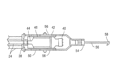
rate. Improved maintenance techniques and equipment can improve efficiency and
advance
technology.
100041 A tuyere is a nozzle through which air and other gases are blown
into a blast furnace
via a blow pipe under pressure from a blast engine or other device. Injection
through the tuyere
creates furnace temperatures far higher than could be normally achieved. A
modern blast furnace
contains 24 to 36 tuyeres. Tuyeres are constructed from pure copper and cooled
with internal
water pipes to withstand the extreme temperatures. A typical tuyere measures
18 in. in end
diameter on the intake end, 6 1/4 in. to 7 % in. diameter at the nose end and
are approximately
1
CA 02877672 2014-12-22
WO 2012/177964 PCT/US2012/043679
21 in. in length. They are very heavy and pressed hydraulically into a cooler
inserted in a tymp
(hollow water-cooled iron cushing) in the furnace wall to a pressure of 5000
lb. The noses can
be heavily damaged by the furnace environment and removing a heavy, damaged
tuyere press-fit
into the cooler is no small task, especially for a manual system.
[0005] Compounding the challenge is the demanding environment of the tuyeres
and the often
limited space in which to access the tuyeres for installation and maintenance.
The life of a tuyere
varies (from several days to several months) and can breakdown by burning and
defoimation of
the tuyere walls caused by materials, such as skull, in the furnace
environment. The loss can
often be catastrophic in the case of water leakage which results in molten
iron and gases escaping
the pressurized furnace. A ten minute break out can result in a multimillion
dollar loss and days
of furnace down time. The replacement of one single tuyere without a break out
typically
interrupts the operation of the furnace for one hour or more, depending on the
length of time the
tuyere has been in the furnace and the amount of damage, at a downtime cost of
several thousand
of dollars per minute.
[0006] Lin, et al., U.S. Pat. 5,925,312, describe a device for removing
tuyeres. The device
utilizes a hydraulic cylinder attached to a rod having an attached hook. The
device is moved into
position in line with the tuyere, the hook engaged, and the hydraulic cylinder
is activated to pull
the tuyere from its tymp.
[0007] A hydraulic cylinder or ram is also employed in U.S. Pat. 4,087,084, to
Meyers, to aid in
the loosening of the tuyere from its tymp. But here, a hydraulic hammer,
placed on a parallel
axis with the rod, supplies vibration to the rod to aid in loosening the
tuyere. The tuyere is then
removed by action of the hydraulic cylinder. The hydraulic hammer provides
vibration, but does
not utilize the force of the hammer to pull the tuyere.
2
CA 02877672 2014-12-22
WO 2012/177964 PCT/US2012/043679
[0008] Malliet describes tuyere removal devices and movable supports to
utilize the device.
U.S. Pat. 5,127,633 describes the device with an air percussion hammer mounted
co-axial with a
double-piston ram and cylindrical rod mounted therein. The rod has a notch or
hook at the end
gripped by the ram. Malleit, in U.S. Pat. 4,266,907, mounts the device onto a
self-propelled
vehicle. The co-axial arrangement of the hammer and rod provides a
reciprocating impact onto
the tuyere, but the energy provided by the air percussion hammer is in a
forward, pushing
direction instead of the desired pulling direction.
[0009] Other existing tuyere removal methods may be entirely manual process
and involve
multiple operators manoeuvring a charge cart with a counterweighted component
handling
means and rope system to haul the tuyere out of the furnace wall. This method
often takes
several attempts and injury to operators is not uncommon. More automated
systems for tuyere
removal utilize hydraulic cylinders to pull the tuyere, but attached hammers
are used either to
vibrate the removal tool or push the tuyere.
[0010] A need for a removal device and method that quickly and easily pulls
the tuyere from its
tymp, reducing downtime, as well as preventing operator injuries, is desired.
SUMMARY OF THE INVENTION
[0011] Hammer means are reverse mounted into a hammer frame. The working end
of the
hammer is fixedly attached to a slidable frame. The slidable frame is slidably
attached to the
sides of the hammer frame. The slidable frame is fixedly attached it to an
elongated lifting arm
means with a component handling means at the end. The component handling means
is engaged
in the back side of a tuyere.
[0012] The hammer frame may be attached to the boom of a small excavator. As
the hammer is
activated by an operator of the excavator, the slidable frame moves relative
to the hammer frame
3
CA 02877672 2014-12-22
WO 2012/177964 PCT/US2012/043679
and the excavator, applying energy into a pulling motion on the elongated
lifting arm means and
component handling means and, concomitantly, the tuyere.
[0013] Using the apparatus with the reverse hammer design, tuyere removal time
was reduced
from 1 hour to a few minutes. Over 24 tuyeres, this represents a significant
reduction in
downtime costs. The system is much safer than other designs as only the
excavator operator is
involved in the removal after the blow pipe and other equipment were
disconnected.
[0014] In a preferred embodiment, the present invention combines the use of a
reverse mounted
hammer fixedly attached by means of a slidable frame to a elongated lifting
aim means with a
component handling means for pulling on a tuyere, generating the force needed
to remove a
tuyere from a blast furnace wall. These and other advantages of the invention
will be
appreciated by reference to the detailed description of the preferred
embodiment(s) that follow.
BRIEF DESCRIPTION OF THE DRAWINGS:
[0015] FIG. 1: Side view of an Excavator with boom, stick, and bucket.
[0016] FIG. 2: Side view of Excavator Arm, Hammer Frame, Sliding Frame,
Elongated lifting
aim means, Component handling means, and Tuyere.
[0017] FIG. 3: Top view of Side Plate Hammer, Sliding Frame, Elongated lifting
arm means,
and Component handling means.
[0018] FIG. 4: Cross view of Side Plate Hammer, Sliding Frame, Elongated
lifting arm means
perpendicular to the axis of the hammer means.
[0019] FIG. 5: Rear view of Side Plate Hammer and Sliding Frame.
[0020] FIG. 6: Side elevational view of a preferred one-piece Sliding Frame of
the present
invention.
[0021] FIG. 7: Top plan view of a preferred one-piece Sliding Frame of the
present invention.
4
CA 02877672 2014-12-22
WO 2012/177964 PCT/US2012/043679
DETAILED DESCRIPTION OF PREFERRED
EMBODIMENT(S) OF THE INVENTION
[0022] In the following detailed description, reference is made to the
accompanying examples
and figures that foi in a part hereof, and in which is shown, by way of
illustration, specific
embodiments in which the inventive subject matter may be practiced. These
embodiments are
described in sufficient detail to enable those skilled in the art to practice
them, and it is to be
understood that other embodiments may be utilized and that structural or
logical changes may be
made without departing from the scope of the inventive subject matter. Such
embodiments of
the inventive subject matter may be referred to, individually and/or
collectively, herein by the
term "invention" merely for convenience and without intending to voluntarily
limit the scope of
this application to any single invention or inventive concept if more than one
is in fact disclosed.
The following description is, therefore, not to be taken in a limited sense,
and the scope of the
inventive subject matter is defined by the appended claims and their
equivalents.
[0023] FIGS. 1 & 2 show a preferred embodiment of a tuyere removing apparatus
10 according
to the present invention comprising a tractor or other motorized vehicle 20
with an operator cab
22, a boom 24, and a tuyere removing attachment 26. Preferably, in the tuyere
removing
apparatus 10, the boom 24 lays flatter to reduce the boom's working height and
allows the center
of gravity of the tuyere remover apparatus 10 to be closer to the cab 22 to
compensate for the
weight of a tuyere when carried by tuyere removing apparatus 10 on removal.
[0024] Referring to FIG. 2, a preferred embodiment of the tuyere remover 10 of
the present
invention comprises hammer 40, hammer frame 46 and one-piece sliding frame 50.
The end 36
of boom 24 may be pivotally attached to a hammer frame 46 having a first end
38 of a hammer
frame 46. A hammer 40 is fixed by attachment means to the second end of the
hammer frame 42
so that the longitudinal axis of the hammer 40 is co-linear with the
longitudinal axis of the
CA 02877672 2014-12-22
WO 2012/177964 PCT/US2012/043679
hammer frame 46. Preferably, the hammer working end 44 is nearer the first end
38 of the
hammer frame 46, thus in a reversed hammer configuration. The attachment means
may be
bolts, welding or any other means to temporarily or peimanently prevent
movement between the
hammer 40 and the hammer frame 46. The hammer 40 may be controlled by
hydraulic or
pneumatic means 48.
[0025] The hammer working end 44 is attached to a sliding frame 50 at a
sliding frame first end
52. The sliding frame 50 is of a general rectangular shape with the first end
52, a second end 54,
and two sides 56 connecting the sliding frame first end 52 and second end 54.
The sliding frame
50 defines an opening of sufficient length and width to accommodate the hammer
frame 46. The
sliding frame 50 is slidably attached by sliding means 66 to the hammer frame
46 such that when
the hammer 40 is activated by hydraulic or pneumatic means, the sliding frame
50 moves in
conjunction with the hammer working end 44 and moves relative to the hammer
frame 42. The
sliding means 66 may comprise brackets 64. The sliding frame second end 54 may
be attached to
one end an elongated lifting arm means 56 having a component handling means 58
at the other
end. The component handling means 58 is designed to fit into the inside of a
tuyere 60 which is
mounted in the wall of the blast furnace 62. The component handling means 58
is preferably a
hook which preferably engages or hooks onto a rim 63 on the inside of tuyere
60. The overall
length of the device from the first end 38 of the hammer frame 46 to the
component handling
means 58 is preferably about 7 feet.
[0026] The hammer 40 preferably is designed to deliver a maximum of 200-400 J
per blow.
More preferably, the hammer 40 is designed to deliver 400 J per blow. As the
hammer 40 is
reverse mounted, the energy of impact is sharply directed to a pulling motion
on the inside of the
tuyere 60.
6
CA 02877672 2014-12-22
WO 2012/177964 PCT/US2012/043679
[0027] FIG. 3 shows the top view of the tuyere remover 10 of the present
invention. The
hammer 40 is reverse attached to the second end 42 of hammer frame 46 such
that the hammer
working end 44 is proximal to the boom 24. The sliding frame 50 is attached to
the hammer
working end 44. The sliding frame sides 56 are slidably attached to the
outside of the hammer
frame 46. The elongated lifting arm means 58 is attached to the second end 54
of the sliding
frame 50.
[0028] FIG. 4 shows the cross view of the tuyere remover 10 midway and
perpendicular to the
axis of the hammer means 40. The sliding frame sides 56 are mounted within
brackets 64
affixed to the hammer frame 46.
[0029] FIG. 5 shows a rear view of the tuyere remover showing the attachment
of the sliding
frame 50 to the hammer working end 44.
[0030] During use, an operator in the cab 22 moves the apparatus into position
such that the
component handling means 58 engages a tuyere 60 to be removed. The hammer 40
is then
activated by hydraulic or pneumatic means 48. The hammer working end 44 moves
out and in.
The sliding frame 50 attached to the hammer working end 44 moves in
conjunction with the
hammer working end 44, and slidably with respect to the hammer frame 46. The
elongated
lifting ami means 58 attached to the sliding frame moves in conjunction with
the sliding frame
and hammer working end 44. The component handling means 58 vibrates on the
tuyere with
each movement of the hammer working end 44. When the tuyere 60 is loose, it is
pulled from
the blast furnace wall 62 by the tuyere removing device 10, generally by
backing up device to
with the tuyere 10 thereon and carried away on the component handling means
58.
[0031] In the foregoing Detailed Description, various features may be grouped
together in a
single embodiment to streamline the disclosure. This method of disclosure is
not to be
7
CA 02877672 2016-10-04
interpreted as reflecting an intention that the embodiments of the invention
require more features
than are expressly recited. Rather, inventive subject matter lies in less than
all features of a single
disclosed embodiment.
8