Note: Descriptions are shown in the official language in which they were submitted.
TITLE
ULTRASONIC SURGICAL INSTRUMENTS WITH DISTALLY POSITIONED JAW
ASSEMBLIES
CROSS-REFERENCE TO RELATED APPLICATIONS
[0001] The present application is related to the following, concurrently-filed
U.S. Patent
Applications:
100021 U.S. Application Serial No. 13/539,096, entitled "Haptic Feedback
Devices for
Surgical Robot," now U.S. Patent Application Publication No. 2014/0005682;
[00031 U.S. Application Serial No. 13/539,110, entitled "Lockout Mechanism for
Use
with Robotic Electrosurgical Device, now U.S. Patent Application Publication
No. 2014/0005654;
[0004] U.S. Application Serial No. 13/539,117, entitled "Closed Feedback
Control for
Electrosurgical Device," now U.S. Patent Application Publication No.
2014/0005667;
[0005] U.S. Application Serial No. 13/538,588, entitled "Surgical Instruments
with
Articulating Shafts," now U.S. Patent Application Publication No.
2014/0005701;
[0006] U.S. Application Serial No. 13/538,601, entitled "Ultrasonic Surgical
Instruments
with Distally Positioned Transducers," now U.S. Patent Application Publication
No.
2014/0005702;
[0007] U.S. Application Serial No. 13/538,700, entitled "Surgical Instruments
with
Articulating Shafts," now U.S. Patent Application Publication No.
2014/0005703;
[0008] U.S. Application Serial No. 13/238,720, entitled "Surgical Instruments
with
Articulating Shafts," now U.S. Patent Application Publication No.
2014/0005705;
[0009] U.S. Application Serial No. 13/538,733, entitled "Ultrasonic Surgical
Instruments
with Control Mechanisms," now U.S. Patent Application Publication No. 2014/
0005681; and
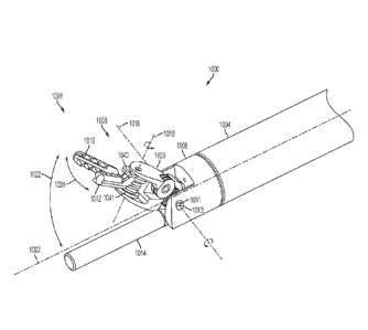
[0010] U.S. Application Serial No. 13/539,122, entitled "Surgical Instruments
With Fluid
Management System" now U.S. Patent Application Publication No. 2014/0005668.
BACKGROUND
[0011] Various embodiments are directed to surgical instruments including
ultrasonic
instruments distally positioned jaw assemblies.
CAN_DMS: \131196418\1 1
CA 2877690 2020-01-02
[0012] Ultrasonic surgical devices, such as ultrasonic scalpels, are used in
many
applications in surgical procedures by virtue of their unique performance
characteristics.
Depending upon specific device configurations and operational parameters,
ultrasonic surgical
devices can provide substantially simultaneous transection of tissue and
homeostasis by
coagulation, desirably minimizing patient trauma. An ultrasonic surgical
device comprises a
proximally-positioned ultrasonic transducer and an instrument coupled to the
ultrasonic
transducer having a distally-mounted end effector comprising an ultrasonic
blade to cut and seal
tissue. The end effector is typically coupled either to a handle and/or a
robotic surgical
implement via a shaft. The blade is acoustically coupled to the transducer via
a waveguide
extending through the shaft. Ultrasonic surgical devices of this nature can be
configured for
open surgical use, laparoscopic, or endoscopic surgical procedures including
robotic-assisted
procedures.
[0013] Ultrasonic energy cuts and coagulates tissue using temperatures lower
than
those used in electrosurgical procedures. Vibrating at high frequencies (e.g.,
55,500 times per
second), the ultrasonic blade denatures protein in the tissue to form a sticky
coagulum. Pressure
exerted on tissue by the blade surface collapses blood vessels and allows the
coagulum to form a
hemostatic seal. A surgeon can control the cutting speed and coagulation by
the force applied to
the tissue by the end effector, the time over which the force is applied and
the selected excursion
level of the end effector.
[0014] It is often desirable for clinicians to articulate a distal portion of
the instrument
shaft in order to direct the application of ultrasonic and/or RF energy. Such
articulation is
challenging and often limited in embodiments where an ultrasonic waveguide
extends from a
proximally-positioned transducer to the distally-positioned ultrasonic blade.
SUMMARY
[0014a] In accordance with an aspect, there is provided a surgical instrument
comprising: an ultrasonic blade positioned at a distal end of an ultrasonic
waveguide, the
ultrasonic waveguide extending distally substantially parallel to a
longitudinal axis; a shaft
extending proximally from the ultrasonic blade along the longitudinal axis;
and a jaw assembly,
wherein the jaw assembly comprises: a wrist member pivotable about a wrist
pivot axis
substantially perpendicular to the longitudinal axis from a first position
where the wrist member
CAN_DMS: \1311964181 2
CA 2877690 2020-01-02
is substantially parallel to the ultrasonic blade to a second position where
the wrist member is
pivoted away from the ultrasonic blade, wherein the wrist pivot axis is offset
from the ultrasonic
blade in an offset direction that is perpendicular to the longitudinal axis; a
first jaw member
extending distally from and pivotably coupled to the wrist member, wherein the
first jaw
member is pivotable about a jaw pivot axis substantially perpendicular to the
wrist pivot axis;
and a second jaw member extending distally from and pivotably coupled to the
wrist member,
wherein the second jaw member is pivotable about the jaw pivot axis, and
wherein the first and
second jaw members are further pivotable about the jaw pivot axis relative to
one another from
an open position where the first and second jaw members are pivoted away from
one another to a
closed position where the first and second jaw members are pivoted towards one
another.
[0014b] In accordance with an aspect, there is provided a surgical instrument
comprising: an ultrasonic blade positioned at a distal end of an ultrasonic
waveguide, the
ultrasonic waveguide extending distally substantially parallel to a
longitudinal axis; a shaft
extending proximally from the ultrasonic blade along the longitudinal axis;
and a jaw assembly
comprising first and second jaw members, wherein the jaw assembly is pivotable
about a first
axis substantially perpendicular to the longitudinal axis from a first
position where the first and
second jaw members are substantially parallel to the ultrasonic blade to a
second position,
wherein the first and second jaw members are pivotable about a second axis
substantially
perpendicular to the first axis, and wherein the first axis is offset from the
ultrasonic blade in an
offset direction that is perpendicular to the longitudinal axis.
10014c] In accordance with an aspect, there is provided a surgical instrument,
comprising: a hollow shaft that extends along a longitudinal axis; a jaw
assembly comprising:a
wrist member comprising a proximal end and a distal end, wherein the proximal
end of the wrist
member is coupled to a distal portion of the hollow shaft, wherein the distal
end of the wrist
member extends beyond the distal portion of the hollow shaft, wherein the
wrist member is
configured to pivot about a wrist axis between a first position and a second
position, wherein the
wrist member is substantially parallel to the longitudinal axis in the first
position, and wherein
the wrist member is skew from the longitudinal axis in the second position; a
first jaw; anda
second jaw, wherein the first and second jaws are pivotably coupled to the
distal end of the wrist
member, and wherein the first and second jaws are configured to pivot relative
to one another
about a jaw axis between an open position and a closed position; a waveguide
that
CAN_DMS: \131196418\1 2a
CA 2877690 2020-01-02
extends proximally through the hollow shaft; and an ultrasonic blade coupled
to the waveguide,
wherein the ultrasonic blade extends distally from the waveguide along an
ultrasonic blade axis
that is substantially parallel to and laterally offset from the longitudinal
axis, wherein the
ultrasonic blade is longitudinally translatable to at least partially retract
the ultrasonic blade from
a position outside of the hollow shaft to a position within the hollow shaft,
and wherein the jaw
assembly is configured to capture tissue and maneuver the captured tissue
towards the ultrasonic
blade.
10014d] In accordance with an aspect, there is provided a surgical instrument,
comprising: a hollow shaft that extends along a longitudinal axis; a jaw
assembly coupled to a
distal portion of the hollow shaft, wherein the jaw assembly comprises: a
wrist member
configured to pivot about a wrist axis between a first position and a second
position, wherein the
wrist member is substantially parallel to the longitudinal axis in the first
position, and wherein
the wrist member is skew from the longitudinal axis in the second position; a
first jaw; and a
second jaw, wherein the first and second jaws are pivotably coupled to the
wrist member, and
wherein the first and second jaws are configured to pivot relative to one
another about a jaw axis
between an open position and a closed position; a waveguide that extends
proximally through the
hollow shaft; and an ultrasonic blade coupled to the waveguide, wherein the
ultrasonic blade
extends distally from the waveguide substantially parallel to and offset from
the longitudinal
axis, wherein the ultrasonic blade is longitudinally translatable to at least
partially retract the
ultrasonic blade within the hollow shaft, wherein the ultrasonic blade is
further longitudinally
translatable to extend the ultrasonic blade outside the hollow shaft, and
wherein the ultrasonic
blade is translatable to an extended position, and wherein the wrist member is
pivotable toward
the ultrasonic blade to the second position with at least one of the wrist
member, the first jaw, or
the second jaw in contact with the ultrasonic blade in the extended position.
[0014e] In accordance with an aspect, there is provided a surgical instrument,
comprising: a shaft extending along a shaft axis; a jaw assembly comprising: a
wrist member
comprising a proximal end and a distal end, wherein the proximal end of the
wrist member is
pivotably coupled to a distal end of the shaft, and wherein the distal end of
the wrist member
extends beyond the distal portion of the shaft; and a first jaw member and a
second jaw member
pivotably coupled to the distal end of the wrist member, wherein the jaw
assembly is configured
to pivot about a first axis between a first location and a second location,
wherein the first and
CAN_DMS: VI31196418\1 2b
CA 2877690 2020-01-02
second jaw members are positioned substantially parallel to the shaft axis at
the first location,
and wherein the first and second jaw members are positioned at an angle from
the shaft axis at
the second location; and an ultrasonic assembly comprising an ultrasonic
blade, a waveguide,
and a transducer, wherein the ultrasonic assembly extends along an ultrasonic
assembly asix that
is substantially parallel to and laterally offset from the shaft axis, wherein
the ultrasonic
assembly is axially translatable to at least partially retract the ultrasonic
blade from a position
outside the safht to a position within the shaft, and wherein the jaw assembly
is configured to
capture tissue and move the captured tissue towards the ultrasonic assembly.
1001411 In accordance with an aspect, there is provided a surgical tool,
comprising: a
cylindrical shaft extending along a longitudinal axis;a tissue grasping
mechanism comprising: a
wrist member comprising a proximal end and a distal end, wherein the proximal
end of the wrist
member is pivotably coupled to a distal end of the cylindrical shaft, and
wherein the distal end of
the wrist member extends beyond the distal portion of the cylindrical shaft;
and a first gripping
member and a second gripping member pivotably coupled to the distal end of the
wrist member,
and wherein the tissue grasping mechanism is configured to rotate about a
first axis substantially
perpendicular to the longitudinal axis; an ultrasonic assembly, comprising: an
ultrasonic blade;
and a waveguide coupled to and extending proximally from the ultrasonic blade
through the
cylindrical shaft; wherein the ultrasonic assembly extends along an ultrasonic
assembly axis that
is substantially parallel to and laterally offset from the longitudinal axis,
wherein the ultrasonic
assembly is longitudinally translatable to at least partially retract the
ultrasonic blade from a
position outside of the cylindrical shaft to a position within the cylindrical
shaft, and wherein the
tissue grasping mechanism is configured to capture tissue and move the
captured tissue towards
the ultrasonic assembly; and an instrument mounting portion coupled to and
extending
proximally from the cylindrical shaft, wherein the instrument mounting portion
comprises an
actuator configured to longitudinally translate the ultrasonic assembly.
DRAWINGS
[0015] The features of the various embodiments are set forth with
particularity in the
appended claims. The various embodiments, however, both as to organization and
methods of
operation, together with advantages thereof, may best be understood by
reference to the
following description, taken in conjunction with the accompanying drawings as
follows:
CANDMS: \131196418\1 2c
CA 2877690 2020-01-02
100161 FIG. 1 illustrates one embodiment of a surgical system including a
surgical
instrument and an ultrasonic generator.
CAN_DMS: 1131196418\1 2d
CA 2877690 2020-01-02
CA 02877690 2014-12-22
WO 2014/004120 PCMJS2013/045828
[0017] FIG. 2 illustrates one embodiment of the surgical instrument shown in
FIG. 1.
[0018] FIG. 3 illustrates one embodiment of an ultrasonic end effector.
[0019] FIG. 4 illustrates another embodiment of an ultrasonic end effector.
100201 FIG. 5 illustrates an exploded view of one embodiment of the surgical
instrument shown in FIG. 1.
[0021] FIG. 6 illustrates a cut-away view of one embodiment of the surgical
instrument
shown in FIG. 1.
[0022] FIG. 7 illustrates various internal components of one embodiment of the
surgical
instrument shown in FIG. 1
[0023] FIG. 8 illustrates a top view of one embodiment of a surgical system
including a
surgical instrument and an ultrasonic generator.
[0024] FIG. 9 illustrates one embodiment of a rotation assembly included in
one
example embodiment of the surgical instrument of FIG. 1.
[0025] FIG. 10 illustrates one embodiment of a surgical system including a
surgical
instrument having a single element end effector.
[0026] FIG. 11 illustrates a block diagram of one embodiment of a robotic
surgical
system.
[0027] FIG. 12 illustrates one embodiment of a robotic arm cart.
[0028] FIG. 13 illustrates one embodiment of the robotic manipulator of the
robotic
arm cart of FIG. 12.
[0029] FIG. 14 illustrates one embodiment of a robotic arm cart having an
alternative
set-up joint structure.
[0030] FIG. 15 illustrates one embodiment of a controller that may be used in
conjunction with a robotic arm cart, such as the robotic arm carts of FIGS. 11-
14.
[0031] FIG. 16 illustrates one embodiment of an ultrasonic surgical instrument
adapted
for use with a robotic system.
FIG. 25 illustrates one embodiment of an electrosurgical instrument adapted
for use with
a robotic system.
[0032] FIG. 17 illustrates one embodiment of an instrument drive assembly that
may be
coupled to a surgical manipulators to receive and control the surgical
instrument shown in FIG.
16.
3
CA 02877690 2014-12-22
WO 2014/004120 PCMJS2013/045828
[0033] FIG. 18 illustrates another view of the instrument drive assembly
embodiment
of FIG. 26 including the surgical instrument of FIG. 16.
[0034] FIGS. 19-21 illustrate additional views of the adapter portion of the
instrument
drive assembly embodiment of FIG. 26.
[0035] FIGS. 22-24 illustrate one embodiment of the instrument mounting
portion of
FIG. 16 showing components for translating motion of the driven elements into
motion of the
surgical instrument.
[0036] FIGS. 25-27 illustrate an alternate embodiment of the instrument
mounting
portion of FIG. 16 showing an alternate example mechanism for translating
rotation of the driven
elements into rotational motion about the axis of the shaft and an alternate
example mechanism
for generating reciprocating translation of one or more members along the axis
of the shaft.
[0037] FIGS. 28-32 illustrate an alternate embodiment of the instrument
mounting
portion FIGS. 16 showing another alternate example mechanism for translating
rotation of the
driven elements into rotational motion about the axis of the shaft.
[0038] FIGS. 33-36A illustrate an alternate embodiment of the instrument
mounting
portion showing an alternate example mechanism for differential translation of
members along
the axis of the shaft (e.g., for articulation).
[0039] FIGS. 36B-36C illustrate one embodiment of a tool mounting portion
comprising internal power and energy sources.
[0040] FIGS. 37-38 illustrates one embodiment of a distal portion of a
surgical
instrument comprising a distally positioned jaw assembly.
[0041] FIG. 39 illustrates a head-on view of one embodiment of the distal
portion of the
surgical instrument of FIGS. 37-38.
[0042] FIGS. 40-41 illustrate one embodiment of the distal portion of the
surgical
instrument of FIGS. 37-38 coupled to an instrument mounting portion for use
with a robotic
surgical system.
[0043] FIGS. 42-44 illustrate one embodiment of the distal portion of the
surgical
instrument of FIGS. 37-38 showing additional control mechanisms.
[0044] FIG. 45A illustrates one embodiment of the instrument mounting portion
showing an example mechanism for actuating various control lines of the
surgical instrument of
FIGS. 37-38.
4
CA 02877690 2014-12-22
WO 2014/004120 PCMJS2013/045828
[0045] FIG. 45B illustrates a side view of one embodiment of the routers.
[0046] FIGS. 46-47 illustrate one embodiment of the distal portion of the
surgical
instrument of FIGS. 37-38 with a retractable ultrasonic blade.
100471 FIG. 48 illustrates one embodiment of the distal portion of the
surgical
instrument of FIGS. 37-38 coupled to an instrument mounting portion of a
robotic surgical
system configured to extend and retract the ultrasonic blade.
[0048] FIG. 49 illustrates an alternate embodiment of the distal portion of
the surgical
instrument of FIGS. 37-38 coupled to an instrument mounting portion of a
robotic surgical
system with an external transducer.
[0049] FIG. 50 illustrates an additional view of the distal portion of the
surgical
instrument of FIGS. 37-38 as illustrated in FIG. 49.
[0050] FIG. 51 illustrates one embodiment of the jaw assembly comprising a
clamp
pad.
[0051] FIGS. 52-56 illustrate one embodiment of a distal portion of a surgical
instrument comprising a jaw assembly with a U-shaped jaw member.
DESCRIPTION
[0052] Various embodiments described herein are directed to surgical
instruments
comprising distally positioned, articulatable jaw assemblies. The jaw
assemblies may be utilized
in lieu of or in addition to shaft articulation. For example, the jaw
assemblies may be utilized to
grasp tissue and move it towards an ultrasonic blade, RF electrodes or other
component for
treating tissue.
[0053] According to one example embodiments, a surgical instrument may
comprise an
end effector with an ultrasonic blade extending distally therefrom. The jaw
assembly may be
articulatable and may pivot about at least two axes. A first axis, or wrist
pivot axis, may be
substantially perpendicular to a longitudinal axis of the instrument shaft.
The jaw assembly may
pivot about the wrist pivot axis from a first position where the jaw assembly
is substantially
parallel to the ultrasonic blade to a second position where the jaw assembly
is not substantially
parallel to the ultrasonic blade. In addition, the jaw assembly may comprise
first and second jaw
members that are pivotable about a second axis or jaw pivot axis. The jaw
pivot axis may be
substantially perpendicular to the wrist pivot axis. In some embodiments, the
jaw pivot axis
CA 02877690 2014-12-22
WO 2014/004120 PCT/US2013/045828
itself may pivot as the jaw assembly pivots about the wrist pivot axis. The
first and second jaw
members may be pivotably relative to one another about the jaw pivot axis such
that the first and
second jaw members may "open" and "close." Additionally, in some embodiments,
the first and
second jaw members are also pivotable about the jaw pivot axis together such
that the direction
of the first and second jaw members may change.
[0054] In various embodiments, the jaw assembly is controlled by a series of
lines
and/or cables that extend proximally from the jaw assembly to a manual handle
and/or
instrument mounting portion of a robotic surgical system. First and second
lines may control
pivoting of the jaw assembly about the wrist pivot axis. A first line may be
coupled to the jaw
assembly at a position offset from the wrist pivot axis. A second line may be
coupled to the jaw
assembly at a second position offset from the wrist pivot axis and
substantially opposite the first
position. Differential translation of the first and second lines may cause
pivoting of the jaw
assembly about the wrist pivot axis. For example, proximal translation of one
of the lines may
cause the jaw assembly to pivot away from the longitudinal axis of the shaft
towards the
proximally translated line. In some embodiments, the jaw assembly may comprise
a pulley
positioned about the wrist pivot axis. The first and second lines may be first
and second ends of
a single line wrapped around the pulley.
[0055] The first and second jaw members may be similarly controlled. For
example, in
some embodiments, each jaw member is coupled to two control lines that extend
proximally
from the jaw assembly through the shaft to the manual handle and/or instrument
mounting
portion of the robotic surgical system. The control lines for each jaw member
may be offset
from one another about the jaw pivot axis such that proximal translation of
one control line
pivots the jaw about the jaw pivot axis in a first direction and proximal
translation of the other
control line pivots the jaw about the jaw pivot axis in a second direction
opposite the first. In
some embodiments the first and second jaw members comprise pulleys positioned
about the jaw
pivot axis and the first and second control lines for each jaw member are ends
of a single control
line wrapped around the respective pulleys. In some embodiments, the jaw
members are
separately controllable. For example, the jaw members may open and close about
the jaw pivot
axis and may additional pivot together about the jaw pivot axis.
[0056] Reference will now be made in detail to several embodiments, including
embodiments showing example implementations of manual and robotic surgical
instruments with
6
CA 02877690 2014-12-22
WO 2014/004120 PCMJS2013/045828
end effectors comprising ultrasonic and/or electrosurgical elements. Wherever
practicable
similar or like reference numbers may be used in the figures and may indicate
similar or like
functionality. The figures depict example embodiments of the disclosed
surgical instruments
and/or methods of use for purposes of illustration only. One skilled in the
art will readily
recognize from the following description that alternative example embodiments
of the structures
and methods illustrated herein may be employed without departing from the
principles described
herein.
[0057] FIG. 1 is a right side view of one embodiment of an ultrasonic surgical
instrument 10. In the illustrated embodiment, the ultrasonic surgical
instrument 10 may be
employed in various surgical procedures including endoscopic or traditional
open surgical
procedures. In one example embodiment, the ultrasonic surgical instrument 10
comprises a
handle assembly 12, an elongated shaft assembly 14, and an ultrasonic
transducer 16. The
handle assembly 12 comprises a trigger assembly 24, a distal rotation assembly
13, and a switch
assembly 28. The elongated shaft assembly 14 comprises an end effector
assembly 26, which
comprises elements to dissect tissue or mutually grasp, cut, and coagulate
vessels and/or tissue,
and actuating elements to actuate the end effector assembly 26. The handle
assembly 12 is
adapted to receive the ultrasonic transducer 16 at the proximal end. The
ultrasonic transducer 16
is mechanically engaged to the elongated shaft assembly 14 and portions of the
end effector
assembly 26. The ultrasonic transducer 16 is electrically coupled to a
generator 20 via a cable
22. Although the majority of the drawings depict a multiple end effector
assembly 26 for use in
connection with laparoscopic surgical procedures, the ultrasonic surgical
instrument 10 may be
employed in more traditional open surgical procedures and in other
embodiments, may be
configured for use in endoscopic procedures. For the purposes herein, the
ultrasonic surgical
instrument 10 is described in terms of an endoscopic instrument; however, it
is contemplated that
an open and/or lap aroscopic version of the ultrasonic surgical instrument 10
also may include the
same or similar operating components and features as described herein.
[0058] In various embodiments, the generator 20 comprises several functional
elements, such as modules and/or blocks. Different functional elements or
modules may be
configured for driving different kinds of surgical devices. For example, an
ultrasonic generator
module 21 may drive an ultrasonic device, such as the ultrasonic surgical
instrument 10. In some
example embodiments, the generator 20 also comprises an electrosurgery/RF
generator module
7
23 for driving an electrosurgical device (or an electrosurgical embodiment of
the ultrasonic
surgical instrument 10). In the example embodiment illustrated in FIG. 1, the
generator 20
includes a control system 25 integral with the generator 20, and a foot switch
29 connected to the
generator via a cable 27. The generator 20 may also comprise a triggering
mechanism for
activating a surgical instrument, such as the instrument 10. The triggering
mechanism may
include a power switch (not shown) as well as a foot switch 29. When activated
by the foot
switch 29, the generator 20 may provide energy to drive the acoustic assembly
of the surgical
instrument 10 and to drive the end effector 18 at a predetermined excursion
level. The generator
20 drives or excites the acoustic assembly at any suitable resonant frequency
of the acoustic
assembly and/or derives the therapeutic/sub-therapeutic electromagnetic/RF
energy.
[0059] In one embodiment, the electrosurgical/RF generator module 23 may be
implemented as an electrosurgery unit (ESU) capable of supplying power
sufficient to perform
bipolar electrosurgery using radio frequency (RF) energy. In one embodiment,
the ESU can be a
bipolar ERBE ICC 350 sold by ERBE USA, Inc. of Marietta, Ga. In bipolar
electrosurgery
applications, as previously discussed, a surgical instrument having an active
electrode and a
return electrode can be utilized, wherein the active electrode and the return
electrode can be
positioned against, or adjacent to, the tissue to be treated such that current
can flow from the ,
active electrode to the return electrode through the tissue. Accordingly, the
electrosurgical/RF
module 23 generator may be configured for therapeutic purposes by applying
electrical energy to
the tissue T sufficient for treating the tissue (e.g., cauterization). For
example, in some
embodiments, the active and/or return electrode may be positioned on the jaw
assembly
described herein.
[0060] In one embodiment, the electrosurgical/RF generator module 23 may be
configured to deliver a subtherapeutic RF signal to implement a tissue
impedance measurement
module. In one embodiment, the electrosurgical/RF generator module 23
comprises a bipolar
radio frequency generator as described in more detail below. In one
embodiment, the
electrosurgical/RF generator module 23 may be configured to monitor electrical
impedance Z, of
tissue T and to control the characteristics of time and power level based on
the tissue T by way
of a return electrode provided on a clamp member of the end effector assembly
26. Accordingly,
the electrosurgical/RF generator module 23 may be configured for
subtherapeutic purposes for
measuring the impedance or other electrical characteristics of the tissue T.
Techniques and
CAN_DMS: \131196418\1 8
CA 2877690 2020-01-02
circuit configurations for measuring the impedance or other electrical
characteristics of tissue T
are discussed in more detail in commonly assigned U.S. Patent Publication No.
2011/0015631,
titled "Electrosurgical Generator for Ultrasonic Surgical Instrument,".
100611 A suitable ultrasonic generator module 21 may be configured to
functionally
operate in a manner similar to the GEN300 sold by Ethicon Endo-Surgery, Inc.
of Cincinnati,
Ohio as is disclosed in one or more of the following U.S. patents: U.S. Pat.
No. 6,480,796
(Method for Improving the Start Up of an Ultrasonic System Under Zero Load
Conditions); U.S.
Pat. No. 6,537,291 (Method for Detecting Blade Breakage Using Rate and/or
Impedance
Information); U.S. Pat. No. 6,662,127 (Method for Detecting Presence of a
Blade in an
Ultrasonic System); U.S. Pat. No. 6,977,495 (Detection Circuitry for Surgical
Handpiece
System); U.S. Pat. No. 7,077,853 (Method for Calculating Transducer
Capacitance to Determine
Transducer Temperature); U.S. Pat. No. 7,179,271 (Method for Driving an
Ultrasonic System to
Improve Acquisition of Blade Resonance Frequency at Startup); and U.S. Pat.
No. 7,273,483
(Apparatus and Method for Alerting Generator Function in an Ultrasonic
Surgical System).
100621 It will be appreciated that in various embodiments, the generator 20
may be
configured to operate in several modes. In one mode, the generator 20 may be
configured such
that the ultrasonic generator module 21 and the electrosurgical/RF generator
module 23 may be
operated independently.
[0063] For example, the ultrasonic generator module 21 may be activated to
apply
ultrasonic energy to the end effector assembly 26 and subsequently, either
therapeutic or sub-
therapeutic RF energy may be applied to the end effector assembly 26 by the
electrosurgical/RF
generator module 23. As previously discussed, the sub-therapeutic
electrosurgical/RF energy
may be applied to tissue clamped between claim elements of the end effector
assembly 26 to
measure tissue impedance to control the activation, or modify the activation,
of the ultrasonic
generator module 21. Tissue impedance feedback from the application of the sub-
therapeutic
energy also may be employed to activate a therapeutic level of the
electrosurgical/RF generator
module 23 to seal the tissue (e.g., vessel) clamped between claim elements of
the end effector
assembly 26.
CAN_DMS:113119641811 9
CA 2877690 2020-01-02
CA 02877690 2014-12-22
WO 2014/004120 PCMJS2013/045828
[0064] In another embodiment, the ultrasonic generator module 21 and the
electrosurgical/RF generator module 23 may be activated simultaneously. In one
example, the
ultrasonic generator module 21 is simultaneously activated with a sub-
therapeutic RF energy
level to measure tissue impedance simultaneously while the ultrasonic blade of
the end effector
assembly 26 cuts and coagulates the tissue (or vessel) clamped between the
clamp elements of
the end effector assembly 26. Such feedback may be employed, for example, to
modify the drive
output of the ultrasonic generator module 21. In another example, the
ultrasonic generator
module 21 may be driven simultaneously with electrosurgical/RF generator
module 23 such that
the ultrasonic blade portion of the end effector assembly 26 is employed for
cutting the damaged
tissue while the electrosurgical/RF energy is applied to electrode portions of
the end effector
clamp assembly 26 for sealing the tissue (or vessel).
[0065] When the generator 20 is activated via the triggering mechanism,
electrical
energy is continuously applied by the generator 20 to a transducer stack or
assembly of the
acoustic assembly. In another embodiment, electrical energy is intermittently
applied (e.g.,
pulsed) by the generator 20. A phase-locked loop in the control system of the
generator 20 may
monitor feedback from the acoustic assembly. The phase lock loop adjusts the
frequency of the
electrical energy sent by the generator 20 to match the resonant frequency of
the selected
longitudinal mode of vibration of the acoustic assembly. In addition, a second
feedback loop in
the control system 25 maintains the electrical current supplied to the
acoustic assembly at a pre-
selected constant level in order to achieve substantially constant excursion
at the end effector 18
of the acoustic assembly. In yet another embodiment, a third feedback loop in
the control system
25 monitors impedance between electrodes located in the end effector assembly
26. Although
FIGS. 1-9 show a manually operated ultrasonic surgical instrument, it will be
appreciated that
ultrasonic surgical instruments may also be used in robotic applications, for
example, as
described herein as well as combinations of manual and robotic applications.
[0066] In ultrasonic operation mode, the electrical signal supplied to the
acoustic
assembly may cause the distal end of the end effector 18, to vibrate
longitudinally in the range
of, for example, approximately 20 kHz to 250 kHz. According to various
embodiments, the
blade 22 may vibrate in the range of about 54 kHz to 56 kHz, for example, at
about 55.5 kHz. In
other embodiments, the blade 22 may vibrate at other frequencies including,
for example, about
31 kHz or about 80 kHz. The excursion of the vibrations at the blade can be
controlled by, for
CA 02877690 2014-12-22
WO 2014/004120 PCMJS2013/045828
example, controlling the amplitude of the electrical signal applied to the
transducer assembly of
the acoustic assembly by the generator 20. As noted above, the triggering
mechanism of the
generator 20 allows a user to activate the generator 20 so that electrical
energy may be
continuously or intermittently supplied to the acoustic assembly. The
generator 20 also has a
power line for insertion in an electro-surgical unit or conventional
electrical outlet. It is
contemplated that the generator 20 can also be powered by a direct current
(DC) source, such as
a battery. The generator 20 can comprise any suitable generator, such as Model
No. GEN04,
and/or Model No. GENII available from Ethicon Endo-Surgery, Inc.
[0067] FIG. 2 is a left perspective view of one example embodiment of the
ultrasonic
surgical instrument 10 showing the handle assembly 12, the distal rotation
assembly 13, the
elongated shaft assembly 14, and the end effector assembly 26. In the
illustrated embodiment
the elongated shaft assembly 14 comprises a distal end 52 dimensioned to
mechanically engage
the end effector assembly 26 and a proximal end 50 that mechanically engages
the handle
assembly 12 and the distal rotation assembly 13. The proximal end 50 of the
elongated shaft
assembly 14 is received within the handle assembly 12 and the distal rotation
assembly 13.
More details relating to the connections between the elongated shaft assembly
14, the handle
assembly 12, and the distal rotation assembly 13 are provided in the
description of FIGS. 5 and
7.
[0068] In the illustrated embodiment, the trigger assembly 24 comprises
a trigger 32
that operates in conjunction with a fixed handle 34. The fixed handle 34 and
the trigger 32 are
ergonomically formed and adapted to interface comfortably with the user. The
fixed handle 34 is
integrally associated with the handle assembly 12. The trigger 32 is pivotally
movable relative to
the fixed handle 34 as explained in more detail below with respect to the
operation of the
ultrasonic surgical instrument 10. The trigger 32 is pivotally movable in
direction 33A toward
the fixed handle 34 when the user applies a squeezing force against the
trigger 32. A spring
element 98 (FIG. 5) causes the trigger 32 to pivotally move in direction 33B
when the user
releases the squeezing force against the trigger 32.
100691 In one example embodiment, the trigger 32 comprises an elongated
trigger hook
36, which defines an aperture 38 between the elongated trigger hook 36 and the
trigger 32. The
aperture 38 is suitably sized to receive one or multiple fingers of the user
therethrough. The
trigger 32 also may comprise a resilient portion 32a molded over the trigger
32 substrate. The
11
CA 02877690 2014-12-22
WO 2014/004120 PCMJS2013/045828
overmolded resilient portion 32a is formed to provide a more comfortable
contact surface for
control of the trigger 32 in outward direction 33B. In one example embodiment,
the overmolded
resilient portion 32a may be provided over a portion of the elongated trigger
hook 36. The
proximal surface of the elongated trigger hook 32 remains uncoated or coated
with a non-
resilient substrate to enable the user to easily slide their fingers in and
out of the aperture 38. In
another embodiment, the geometry of the trigger forms a fully closed loop
which defines an
aperture suitably sized to receive one or multiple fingers of the user
therethrough. The fully
closed loop trigger also may comprise a resilient portion molded over the
trigger substrate.
[0070] In one example embodiment, the fixed handle 34 comprises a proximal
contact
surface 40 and a grip anchor or saddle surface 42. The saddle surface 42 rests
on the web where
the thumb and the index finger are joined on the hand. The proximal contact
surface 40 has a
pistol grip contour that receives the palm of the hand in a normal pistol grip
with no rings or
apertures. The profile curve of the proximal contact surface 40 may be
contoured to
accommodate or receive the palm of the hand. A stabilization tail 44 is
located towards a more
proximal portion of the handle assembly 12. The stabilization tail 44 may be
in contact with the
uppermost web portion of the hand located between the thumb and the index
finger to stabilize
the handle assembly 12 and make the handle assembly 12 more controllable.
[0071] In one example embodiment, the switch assembly 28 may comprise a toggle
switch 30. The toggle switch 30 may be implemented as a single component with
a central pivot
304 located within inside the handle assembly 12 to eliminate the possibility
of simultaneous
activation. In one example embodiment, the toggle switch 30 comprises a first
projecting knob
30a and a second projecting knob 30b to set the power setting of the
ultrasonic transducer 16
between a minimum power level (e.g., MIN) and a maximum power level (e.g.,
MAX). In
another embodiment, the rocker switch may pivot between a standard setting and
a special
setting. The special setting may allow one or more special programs to be
implemented by the
device. The toggle switch 30 rotates about the central pivot as the first
projecting knob 30a and
the second projecting knob 30b are actuated. The one or more projecting knobs
30a, 30b are
coupled to one or more arms that move through a small arc and cause electrical
contacts to close
or open an electric circuit to electrically energize or de-energize the
ultrasonic transducer 16 in
accordance with the activation of the first or second projecting knobs 30a,
30b. The toggle
switch 30 is coupled to the generator 20 to control the activation of the
ultrasonic transducer 16.
12
The toggle switch 30 comprises one or more electrical power setting switches
to activate the
ultrasonic transducer 16 to set one or more power settings for the ultrasonic
transducer 16. The
forces required to activate the toggle switch 30 are directed substantially
toward the saddle point
42, thus avoiding any tendency of the instrument to rotate in the hand when
the toggle switch 30
is activated.
[00721 In one example embodiment, the first and second projecting knobs 30a,
30b are
located on the distal end of the handle assembly 12 such that they can be
easily accessible by the
user to activate the power with minimal, or substantially no, repositioning of
the hand grip,
making it suitable to maintain control and keep attention focused on the
surgical site (e.g., a
monitor in a laparoscopic procedure) while activating the toggle switch 30.
The projecting
knobs 30a, 30b may be configured to wrap around the side of the handle
assembly 12 to some
extent to be more easily accessible by variable finger lengths and to allow
greater freedom of
access to activation in awkward positions or for shorter fingers.
100731 In the illustrated embodiment, the first projecting knob 30a comprises
a plurality
of tactile elements 30c, e.g., textured projections or "bumps" in the
illustrated embodiment, to
allow the user to differentiate the first projecting knob 30a from the second
projecting knob 30b.
It will be appreciated by those skilled in the art that several ergonomic
features may be
incorporated into the handle assembly 12. Such ergonomic features are
described in U.S. Pat.
App. Pub. No. 2009/0105750 entitled "Ergonomic Surgical Instruments", now U.S
Patent
8,623,027.
100741 In one example embodiment, the toggle switch 30 may be operated by the
hand
of the user. The user may easily access the first and second projecting knobs
30a, 30b at any
point while also avoiding inadvertent or unintentional activation at any time.
The toggle switch
30 may readily operated with a finger to control the power to the ultrasonic
assembly 16 and/or
to the ultrasonic assembly 16. For example, the index finger may be employed
to activate the
first contact portion 30a to turn on the ultrasonic assembly 16 to a maximum
(MAX) power
level. The index finger may be employed to activate the second contact portion
30b to turn on
the ultrasonic assembly 16 to a minimum (MIN) power level. In another
embodiment, the rocker
switch may pivot the instrument 10 between a standard setting and a special
setting. The special
setting may allow one or more special programs to be implemented by the
instrument 10. The
toggle switch 30 may be operated without the user having to look at the first
or second projecting
CAN_DMS: \131196418l1 13
CA 2877690 2020-01-02
CA 02877690 2014-12-22
WO 2014/004120 PCMJS2013/045828
knob 30a, 30b. For example, the first projecting knob 30a or the second
projecting knob 30b
may comprise a texture or projections to tactilely differentiate between the
first and second
projecting knobs 30a, 30b without looking.
100751 In one example embodiment, the distal rotation assembly 13 is rotatable
without
limitation in either direction about a longitudinal axis "T." The distal
rotation assembly 13 is
mechanically engaged to the elongated shaft assembly 14. The distal rotation
assembly 13 is
located on a distal end of the handle assembly 12. The distal rotation
assembly 13 comprises a
cylindrical hub 46 and a rotation knob 48 formed over the hub 46. The hub 46
mechanically
engages the elongated shaft assembly 14. The rotation knob 48 may comprise
fluted polymeric
features and may be engaged by a finger (e.g., an index finger) to rotate the
elongated shaft
assembly 14. The hub 46 may comprise a material molded over the primary
structure to form the
rotation knob 48. The rotation knob 48 may be overmolded over the hub 46. The
hub 46
comprises an end cap portion 46a that is exposed at the distal end. The end
cap portion 46a of
the hub 46 may contact the surface of a trocar during laparoscopic procedures.
The hub 46 may
be formed of a hard durable plastic such as polycarbonate to alleviate any
friction that may occur
between the end cap portion 46a and the trocar. The rotation knob 48 may
comprise "scallops"
or flutes formed of raised ribs 48a and concave portions 48b located between
the ribs 48a to
provide a more precise rotational grip. In one example embodiment, the
rotation knob 48 may
comprise a plurality of flutes (e.g., three or more flutes). In other
embodiments, any suitable
number of flutes may be employed. The rotation knob 48 may be formed of a
softer polymeric
material overmolded onto the hard plastic material. For example, the rotation
knob 48 may be
formed of pliable, resilient, flexible polymeric materials including
Versaflex0 TPE alloys made
by GLS Corporation, for example. This softer overmolded material may provide a
greater grip
and more precise control of the movement of the rotation knob 48. It will be
appreciated that
any materials that provide adequate resistance to sterilization, are
biocompatible, and provide
adequate frictional resistance to surgical gloves may be employed to form the
rotation knob 48.
100761 In one example embodiment, the handle assembly 12 is formed from two
(2)
housing portions or shrouds comprising a first portion 12a and a second
portion 12b. From the
perspective of a user viewing the handle assembly 12 from the distal end
towards the proximal
end, the first portion 12a is considered the right portion and the second
portion 12b is considered
the left portion. Each of the first and second portions 12a, 12b includes a
plurality of interfaces
14
69 (FIG. 7) dimensioned to mechanically align and engage each another to form
the handle
assembly 12 and enclosing the internal working components thereof. The fixed
handle 34, which
is integrally associated with the handle assembly 12, takes shape upon the
assembly of the first
and second portions 12a and 12b of the handle assembly 12. A plurality of
additional interfaces
(not shown) may be disposed at various points around the periphery of the
first and second
portions 12a and 12b of the handle assembly 12 for ultrasonic welding
purposes, e.g., energy
direction/deflection points. The first and second portions 12a and 12b (as
well as the other
components described below) may be assembled together in any fashion known in
the art. For
example, alignment pins, snap-like interfaces, tongue and groove interfaces,
locking tabs,
adhesive ports, may all be utilized either alone or in combination for
assembly purposes.
100771 In one example embodiment, the elongated shaft assembly 14 comprises a
proximal end 50 adapted to mechanically engage the handle assembly 12 and the
distal rotation
assembly 13; and a distal end 52 adapted to mechanically engage the end
effector assembly 26.
The elongated shaft assembly 14 comprises an outer tubular sheath 56 and a
reciprocating
tubular actuating member 58 located within the outer tubular sheath 56. The
proximal end of the
tubular reciprocating tubular actuating member 58 is mechanically engaged to
the trigger 32 of
the handle assembly 12 to move in either direction 60A or 60B in response to
the actuation
and/or release of the trigger 32. The pivotably moveable trigger 32 may
generate reciprocating
motion along the longitudinal axis "T." Such motion may be used, for example,
to actuate the
jaws or clamping mechanism of the end effector assembly 26. A series of
linkages translate the
pivotal rotation of the trigger 32 to axial movement of a yoke coupled to an
actuation
mechanism, which controls the opening and closing of the jaws of the clamping
mechanism of
the end effector assembly 26. The distal end of the tubular reciprocating
tubular actuating
member 58 is mechanically engaged to the end effector assembly 26. In the
illustrated
embodiment, the distal end of the tubular reciprocating tubular actuating
member 58 is
mechanically engaged to a clamp arm assembly 64, which is pivotable about a
pivot point 70, to
open and close the clamp arm assembly 64 in response to the actuation and/or
release of the
trigger 32. For example, in the illustrated embodiment, the clamp arm assembly
64 is movable
in direction 62A from an open position to a closed position about a pivot
point 70 when the
trigger 32 is squeezed in direction 33A. The clamp arm assembly 64 is movable
in direction 628
CAN_DMS: 11311964181 15
CA 2877690 2020-01-02
from a closed position to an open position about the pivot point 70 when the
trigger 32 is
released or outwardly contacted in direction 338.
[00781 In one example embodiment, the end effector assembly 26 is attached at
the
distal end 52 of the elongated shaft assembly 14 and includes a clamp arm
assembly 64 and a
blade 66. The jaws of the clamping mechanism of the end effector assembly 26
are formed by
clamp arm assembly 64 and the blade 66. The blade 66 is ultrasonically
actuatable and is
acoustically coupled to the ultrasonic transducer 16. The trigger 32 on the
handle assembly 12 is
ultimately connected to a drive assembly, which together, mechanically
cooperate to effect
movement of the clamp arm assembly 64. Squeezing the trigger 32 in direction
33A moves the
clamp arm assembly 64 in direction 62A from an open position, wherein the
clamp arm assembly
64 and the blade 66 are disposed in a spaced relation relative to one another,
to a clamped or
closed position, wherein the clamp arm assembly 64 and the blade 66 cooperate
to grasp tissue
therebetween. The clamp arm assembly 64 may comprise a clamp pad (not shown)
to engage
tissue between the blade 66 and the clamp arm 64. Releasing the trigger 32 in
direction 33B
moves the clamp arm assembly 64 in direction 62B from a closed relationship,
to an open
position, wherein the clamp arm assembly 64 and the blade 66 are disposed in a
spaced relation
relative to one another.
100791 The proximal portion of the handle assembly 12 comprises a proximal
opening
68 to receive the distal end of the ultrasonic assembly 16. The ultrasonic
assembly 16 is inserted
in the proximal opening 68 and is mechanically engaged to the elongated shaft
assembly 14.
10080] In one example embodiment, the elongated trigger hook 36 portion of the
trigger
32 provides a longer trigger lever with a shorter span and rotation travel.
The longer lever of the
elongated trigger hook 36 allows the user to employ multiple fingers within
the aperture 38 to
operate the elongated trigger hook 36 and cause the trigger 32 to pivot in
direction 33B to open
the jaws of the end effector assembly 26. For example, the user may insert
three fingers (e.g.,
the middle, ring, and little fingers) in the aperture 38. Multiple fingers
allows the surgeon to
exert higher input forces on the trigger 32 and the elongated trigger hook326
to activate the end
effector assembly 26. The shorter span and rotation travel creates a more
comfortable grip when
closing or squeezing the trigger 32 in direction 33A or when opening the
trigger 32 in the
outward opening motion in direction 33B lessening the need to extend the
fingers further
outward. This substantially lessens hand fatigue and strain associated with
the outward opening
CAN_DMS: \13119641811 16
CA 2877690 2020-01-02
motion of the trigger 32 in direction 33B. The outward opening motion of the
trigger may be
spring-assisted by spring element 98 (FIG. 5) to help alleviate fatigue. The
opening spring force
is sufficient to assist the ease of opening, but not strong enough to
adversely impact the tactile
feedback of tissue tension during spreading dissection.
[0081] For example, during a surgical procedure the index finger may be used
to
control the rotation of the elongated shaft assembly 14 to locate the jaws of
the end effector
assembly 26 in a suitable orientation. The middle and/or the other lower
fingers may be used to
squeeze the trigger 32 and grasp tissue within the jaws. Once the jaws are
located in the desired
position and the jaws are clamped against the tissue, the index finger can be
used to activate the
toggle switch 30 to adjust the power level of the ultrasonic transducer 16 to
treat the tissue.
Once the tissue has been treated, the user may release the trigger 32 by
pushing outwardly in the
distal direction against the elongated trigger hook 36 with the middle and/or
lower fingers to
open the jaws of the end effector assembly 26. This basic procedure may be
performed without
the user having to adjust their grip of the handle assembly 12.
100821 FIGS. 3-4 illustrate the connection of the elongated shaft assembly 14
relative to
the end effector assembly 26. As previously described, in the illustrated
embodiment, the end
effector assembly 26 comprises a clamp arm assembly 64 and a blade 66 to form
the jaws of the
clamping mechanism. The blade 66 may be an ultrasonically actuatable blade
acoustically
coupled to the ultrasonic transducer 16. The trigger 32 is mechanically
connected to a drive
assembly. Together, the trigger 32 and the drive assembly mechanically
cooperate to move the
clamp arm assembly 64 to an open position in direction 62A wherein the clamp
arm assembly 64
and the blade 66 are disposed in spaced relation relative to one another, to a
clamped or closed
position in direction 62B wherein the clamp arm assembly 64 and the blade 66
cooperate to
grasp tissue therebetween. The clamp arm assembly 64 may comprise a clamp pad
(not shown)
to engage tissue between the blade 66 and the clamp arm 64. The distal end of
the tubular
reciprocating tubular actuating member 58 is mechanically engaged to the end
effector assembly
26. In the illustrated embodiment, the distal end of the tubular reciprocating
tubular actuating
member 58 is mechanically engaged to the clamp arm assembly 64, which is
pivotable about the
pivot point 70, to open and close the clamp arm assembly 64 in response to the
actuation and/or
release of the trigger 32. For example, in the illustrated embodiment, the
clamp arm assembly 64
is movable from an open position to a closed position in direction 62B about a
pivot point 70
when
CAN_DMS: \131196418\1 17
CA 2877690 2020-01-02
CA 02877690 2014-12-22
WO 2014/004120 PCMJS2013/045828
the trigger 32 is squeezed in direction 33A. The clamp arm assembly 64 is
movable from a
closed position to an open position in direction 62A about the pivot point 70
when the trigger 32
is released or outwardly contacted in direction 33B.
100831 As previously discussed, the clamp arm assembly 64 may comprise
electrodes
electrically coupled to the electrosurgical/RF generator module 23 to receive
therapeutic and/or
sub-therapeutic energy, where the electrosurgical/RF energy may be applied to
the electrodes
either simultaneously or non simultaneously with the ultrasonic energy being
applied to the blade
66. Such energy activations may be applied in any suitable combinations to
achieve a desired
tissue effect in cooperation with an algorithm or other control logic.
[0084] FIG. 5 is an exploded view of the ultrasonic surgical instrument 10
shown in
FIG. 2. In the illustrated embodiment, the exploded view shows the internal
elements of the
handle assembly 12, the handle assembly 12, the distal rotation assembly 13,
the switch
assembly 28, and the elongated shaft assembly 14. In the illustrated
embodiment, the first and
second portions 12a, 12b mate to form the handle assembly 12. The first and
second portions
12a, 12b each comprises a plurality of interfaces 69 dimensioned to
mechanically align and
engage one another to form the handle assembly 12 and enclose the internal
working components
of the ultrasonic surgical instrument 10. The rotation knob 48 is mechanically
engaged to the
outer tubular sheath 56 so that it may be rotated in circular direction 54 up
to 360 . The outer
tubular sheath 56 is located over the reciprocating tubular actuating member
58, which is
mechanically engaged to and retained within the handle assembly 12 via a
plurality of coupling
elements 72. The coupling elements 72 may comprise an 0-ring 72a, a tube
collar cap 72b, a
distal washer 72c, a proximal washer 72d, and a thread tube collar 72e. The
reciprocating
tubular actuating member 58 is located within a reciprocating yoke 84, which
is retained between
the first and second portions 12a, 12b of the handle assembly 12. The yoke 84
is part of a
reciprocating yoke assembly 88. A series of linkages translate the pivotal
rotation of the
elongated trigger hook 32 to the axial movement of the reciprocating yoke 84,
which controls the
opening and closing of the jaws of the clamping mechanism of the end effector
assembly 26 at
the distal end of the ultrasonic surgical instrument 10. In one example
embodiment, a four-link
design provides mechanical advantage in a relatively short rotation span, for
example.
[0085] In one example embodiment, an ultrasonic transmission waveguide 78 is
disposed inside the reciprocating tubular actuating member 58. The distal end
52 of the
18
ultrasonic transmission waveguide 78 is acoustically coupled (e.g., directly
or indirectly
mechanically coupled) to the blade 66 and the proximal end 50 of the
ultrasonic transmission
waveguide 78 is received within the handle assembly 12. The proximal end 50 of
the ultrasonic
transmission waveguide 78 is adapted to acoustically couple to the distal end
of the ultrasonic
transducer 16 as discussed in more detail below. The ultrasonic transmission
waveguide 78 is
isolated from the other elements of the elongated shaft assembly 14 by a
protective sheath 80 and
a plurality of isolation elements 82, such as silicone rings. The outer
tubular sheath 56, the
reciprocating tubular actuating member 58, and the ultrasonic transmission
waveguide 78 are
mechanically engaged by a pin 74. The switch assembly 28 comprises the toggle
switch 30 and
electrical elements 86a,b to electrically energize the ultrasonic transducer
16 in accordance with
the activation of the first or second projecting knobs 30a, 30b.
100861 In one example embodiment, the outer tubular sheath 56 isolates the
user or the
patient from the ultrasonic vibrations of the ultrasonic transmission
waveguide 78. The outer
tubular sheath 56 generally includes a hub 76. The outer tubular sheath 56 is
threaded onto the
distal end of the handle assembly 12. The ultrasonic transmission waveguide 78
extends through
the opening of the outer tubular sheath 56 and the isolation elements 82
isolate the ultrasonic
transmission waveguide 78 from the outer tubular sheath 56. The outer tubular
sheath 56 may be
attached to the waveguide 78 with the pin 74. The hole to receive the pin 74
in the waveguide 78
may occur nominally at a displacement node. The waveguide 78 may screw or snap
into the
hand piece handle assembly 12 by a stud. Flat portions on the hub 76 may allow
the assembly to
be torqued to a required level. In one example embodiment, the hub 76 portion
of the outer
tubular sheath 56 is preferably constructed from plastic and the tubular
elongated portion of the
outer tubular sheath 56 is fabricated from stainless steel. Alternatively, the
ultrasonic
transmission waveguide 78 may comprise polymeric material surrounding it to
isolate it from
outside contact.
[0087] In one example embodiment, the distal end of the ultrasonic
transmission
waveguide 78 may be coupled to the proximal end of the blade 66 by an internal
threaded
connection, preferably at or near an antinode. It is contemplated that the
blade 66 may be
attached to the ultrasonic transmission waveguide 78 by any suitable means,
such as a welded
joint or the like. Although the blade 66 may be detachable from the ultrasonic
transmission
CAN_DMS: 1131196418\1 19
CA 2877690 2020-01-02
waveguide 78, it is also contemplated that the single element end effector
(e.g., the blade 66) and
the ultrasonic transmission waveguide 78 may be formed as a single unitary
piece.
100881 In one example embodiment, the trigger 32 is coupled to a linkage
mechanism
to translate the rotational motion of the trigger 32 in directions 33A and 33B
to the linear motion
of the reciprocating tubular actuating member 58 in corresponding directions
60A and 60B. The
trigger 32 comprises a first set of flanges 97 with openings formed therein to
receive a first yoke
pin 94a. The first yoke pin 94a is also located through a set of openings
formed at the distal end
of the yoke 84. The trigger 32 also comprises a second set of flanges 96 to
receive a first end
92a of a link 92. A trigger pin 90 is received in openings formed in the link
92 and the second
set of flanges 96. The trigger pin 90 is received in the openings formed in
the link 92 and the
second set of flanges 96 and is adapted to couple to the first and second
portions 12a, 12b of the
handle assembly 12 to form a trigger pivot point for the trigger 32. A second
end 92b of the link
92 is received in a slot 93 formed in a proximal end of the yoke 84 and is
retained therein by a
second yoke pin 94b. As the trigger 32 is pivotally rotated about the pivot
point 190 formed by
the trigger pin 90, the yoke translates horizontally along longitudinal axis
"T" in a direction
indicated by arrows 60A,B.
100891 FIG. 8 illustrates one example embodiment of an ultrasonic surgical
instrument
10. In the illustrated embodiment, a cross-sectional view of the ultrasonic
transducer 16 is
shown within a partial cutaway view of the handle assembly 12. One example
embodiment of
the ultrasonic surgical instrument 10 comprises the ultrasonic signal
generator 20 coupled to the
ultrasonic transducer 16, comprising a hand piece housing 99, and an
ultrasonically actuatable
single or multiple element end effector assembly 26. As previously discussed,
the end effector
assembly 26 comprises the ultrasonically actuatable blade 66 and the clamp arm
64. The
ultrasonic transducer 16, which is known as a "Langevin stack", generally
includes a
transduction portion 100, a first resonator portion or end-bell 102, and a
second resonator portion
or fore-bell 104, and ancillary components. The total construction of these
components is a
resonator. The ultrasonic transducer 16 is preferably an integral number of
one-half system
wavelengths (On; where "n" is any positive integer; e.g., n = 1, 2, 3...) in
length as will be
described in more detail later. An acoustic assembly 106 includes the
ultrasonic transducer 16, a
nose cone 108, a velocity transformer 118, and a surface 110.
CAN_DMS: 113119641811 20
CA 2877690 2020-01-02
CA 02877690 2014-12-22
WO 2014/004120 PCMJS2013/045828
[0090] In one example embodiment, the distal end of the end-bell 102 is
connected to
the proximal end of the transduction portion 100, and the proximal end of the
fore-bell 104 is
connected to the distal end of the transduction portion 100. The fore-bell 104
and the end-bell
102 have a length determined by a number of variables, including the thickness
of the
transduction portion 100, the density and modulus of elasticity of the
material used to
manufacture the end-bell 102 and the fore-bell 22, and the resonant frequency
of the ultrasonic
transducer 16. The fore-bell 104 may be tapered inwardly from its proximal end
to its distal end
to amplify the ultrasonic vibration amplitude as the velocity transformer 118,
or alternately may
have no amplification. A suitable vibrational frequency range may be about
20Hz to 32kHz and
a well-suited vibrational frequency range may be about 30-10kHz. A suitable
operational
vibrational frequency may be approximately 55.5kHz, for example.
[0091] In one example embodiment, the piezoelectric elements 112 may be
fabricated
from any suitable material, such as, for example, lead zirconate-titanatc,
lead meta-niobate, lead
titanate, barium titanatc, or other piezoelectric ceramic material. Each of
positive electrodes 114,
negative electrodes 116, and the piezoelectric elements 112 has a bore
extending through the
center. The positive and negative electrodes 114 and 116 are electrically
coupled to wires 120
and 122, respectively. The wires 120 and 122 are encased within the cable 22
and electrically
connectable to the ultrasonic signal generator 20.
[0092] The ultrasonic transducer 16 of the acoustic assembly 106 converts the
electrical
signal from the ultrasonic signal generator 20 into mechanical energy that
results in primarily a
standing acoustic wave of longitudinal vibratory motion of the ultrasonic
transducer 16 and the
blade 66 portion of the end effector assembly 26 at ultrasonic frequencies. In
another
embodiment, the vibratory motion of the ultrasonic transducer may act in a
different direction.
For example, the vibratory motion may comprise a local longitudinal component
of a more
complicated motion of the tip of the elongated shaft assembly 14. A suitable
generator is
available as model number GENII, from Ethicon Endo-Surgery, Inc., Cincinnati,
Ohio. When
the acoustic assembly 106 is energized, a vibratory motion standing wave is
generated through
the acoustic assembly 106. The ultrasonic surgical instrument 10 is designed
to operate at a
resonance such that an acoustic standing wave pattern of predetermined
amplitude is produced.
The amplitude of the vibratory motion at any point along the acoustic assembly
106 depends
upon the location along the acoustic assembly 106 at which the vibratory
motion is measured. A
21
CA 02877690 2014-12-22
WO 2014/004120 PCMJS2013/045828
minimum or zero crossing in the vibratory motion standing wave is generally
referred to as a
node (i.e., where motion is minimal), and a local absolute value maximum or
peak in the
standing wave is generally referred to as an anti-node (e.g., where local
motion is maximal). The
distance between an anti-node and its nearest node is one-quarter wavelength
(V4).
[0093] The wires 120 and 122 transmit an electrical signal from the ultrasonic
signal
generator 20 to the positive electrodes 114 and the negative electrodes 116.
The piezoelectric
elements 112 are energized by the electrical signal supplied from the
ultrasonic signal generator
20 in response to an actuator 224, such as a foot switch, for example, to
produce an acoustic
standing wave in the acoustic assembly 106. The electrical signal causes
disturbances in the
piezoelectric elements 112 in the form of repeated small displacements
resulting in large
alternating compression and tension forces within the material. The repeated
small
displacements cause the piezoelectric elements 112 to expand and contract in a
continuous
manner along the axis of the voltage gradient, producing longitudinal waves of
ultrasonic energy.
The ultrasonic energy is transmitted through the acoustic assembly 106 to the
blade 66 portion of
the end effector assembly 26 via a transmission component or an ultrasonic
transmission
waveguide portion 78 of the elongated shaft assembly 14.
[0094] In one example embodiment, in order for the acoustic assembly 106 to
deliver
energy to the blade 66 portion of the end effector assembly 26, all components
of the acoustic
assembly 106 must be acoustically coupled to the blade 66. The distal end of
the ultrasonic
transducer 16 may be acoustically coupled at the surface 110 to the proximal
end of the
ultrasonic transmission waveguide 78 by a threaded connection such as a stud
124.
[0095] In one example embodiment, the components of the acoustic assembly 106
are
preferably acoustically tuned such that the length of any assembly is an
integral number of one-
half wavelengths (nk/2), where the wavelength X is the wavelength of a pre-
selected or operating
longitudinal vibration drive frequency fd of the acoustic assembly 106. It is
also contemplated
that the acoustic assembly 106 may incorporate any suitable arrangement of
acoustic elements.
[0096] In one example embodiment, the blade 66 may have a length substantially
equal
to an integral multiple of one-half system wavelengths (nX/2). A distal end of
the blade 66 may
be disposed near an antinode in order to provide the maximum longitudinal
excursion of the
distal end. When the transducer assembly is energized, the distal end of the
blade 66 may be
configured to move in the range of, for example, approximately 10 to 500
microns peak-to-peak,
22
CA 02877690 2014-12-22
WO 2014/004120 PCMJS2013/045828
and preferably in the range of about 30 to 64 microns at a predetermined
vibrational frequency of
55kHz, for example.
[0097] In one example embodiment, the blade 66 may be coupled to the
ultrasonic
transmission waveguide 78. The blade 66 and the ultrasonic transmission
waveguide 78 as
illustrated are formed as a single unit construction from a material suitable
for transmission of
ultrasonic energy. Examples of such materials include Ti6A14V (an alloy of
Titanium including
Aluminum and Vanadium), Aluminum, Stainless Steel, or other suitable
materials. Alternately,
the blade 66 may be separable (and of differing composition) from the
ultrasonic transmission
waveguide 78, and coupled by, for example, a stud, weld, glue, quick connect,
or other suitable
known methods. The length of the ultrasonic transmission waveguide 78 may be
substantially
equal to an integral number of one-half wavelengths (nk/2), for example. The
ultrasonic
transmission waveguide 78 may be preferably fabricated from a solid core shaft
constructed out
of material suitable to propagate ultrasonic energy efficiently, such as the
titanium alloy
discussed above (i.e., Ti6A14V) or any suitable aluminum alloy, or other
alloys, for example.
[0098] In one example embodiment, the ultrasonic transmission waveguide 78
comprises a longitudinally projecting attachment post at a proximal end to
couple to the surface
110 of the ultrasonic transmission waveguide 78 by a threaded connection such
as the stud 124.
The ultrasonic transmission waveguide 78 may include a plurality of
stabilizing silicone rings or
compliant supports 82 (FIG. 5) positioned at a plurality of nodes. The
silicone rings 82 dampen
undesirable vibration and isolate the ultrasonic energy from an outer
protective sheath 80 (FIG.
5) assuring the flow of ultrasonic energy in a longitudinal direction to the
distal end of the blade
66 with maximum efficiency.
[0099] FIG. 9 illustrates one example embodiment of the proximal rotation
assembly
128. In the illustrated embodiment, the proximal rotation assembly 128
comprises the proximal
rotation knob 134 inserted over the cylindrical hub 135. The proximal rotation
knob 134
comprises a plurality of radial projections 138 that are received in
corresponding slots 130
formed on a proximal end of the cylindrical hub 135. The proximal rotation
knob 134 defines an
opening 142 to receive the distal end of the ultrasonic transducer 16. The
radial projections 138
are formed of a soft polymeric material and define a diameter that is
undersized relative to the
outside diameter of the ultrasonic transducer 16 to create a friction
interference fit when the
distal end of the ultrasonic transducer 16. The polymeric radial projections
138 protrude radially
23
into the opening 142 to form "gripper" ribs that firmly grip the exterior
housing of the ultrasonic
transducer 16. Therefore, the proximal rotation knob 134 securely grips the
ultrasonic transducer
16.
[0100] The distal end of the cylindrical hub 135 comprises a circumferential
lip 132
and a circumferential bearing surface 140. The circumferential lip engages a
groove formed in
the housing 12 and the circumferential bearing surface 140 engages the housing
12. Thus, the
cylindrical hub 135 is mechanically retained within the two housing portions
(not shown) of the
housing 12. The circumferential lip 132 of the cylindrical hub 135 is located
or "trapped"
between the first and second housing portions 12a, 12b and is free to rotate
in place within the
groove. The circumferential bearing surface 140 bears against interior
portions of the housing to
assist proper rotation. Thus, the cylindrical hub 135 is free to rotate in
place within the housing.
The user engages the flutes 136 formed on the proximal rotation knob 134 with
either the finger
or the thumb to rotate the cylindrical hub 135 within the housing 12.
[0101] In one example embodiment, the cylindrical hub 135 may be formed of a
durable plastic such as polycarbonate. In one example embodiment, the
cylindrical hub 135 may
be formed of a siliconized polycarbonate material. In one example embodiment,
the proximal
rotation knob 134 may be formed of pliable, resilient, flexible polymeric
materials including
Versaflex TPE alloys made by GLS Corporation, for example. The proximal
rotation knob
134 may be formed of elastomeric materials, thermoplastic rubber known as
Santoprene , other
thermoplastic vulcanizates (TPVs), or elastomers, for example. The
embodiments, however, are
not limited in this context.
[0102] FIG. 10 illustrates one example embodiment of a surgical system 200
including
a surgical instrument 210 having single element end effector 278. The system
200 may include a
transducer assembly 216 coupled to the end effector 278 and a sheath 256
positioned around the
proximal portions of the end effector 278 as shown. The transducer assembly
216 and end
effector 278 may operate in a manner similar to that of the transducer
assembly 16 and end
effector 18 described above to produce ultrasonic energy that may be
transmitted to tissue via
blade 226.
[0103] Over the years, a variety of minimally invasive robotic (or
"telesurgical")
systems have been developed to increase surgical dexterity as well as to
permit a surgeon to
operate on a patient in an intuitive manner. Robotic surgical systems can be
used with many
CAN_DMS: \13119641811 24
CA 2877690 2020-01-02
different types of surgical instruments including, for example, ultrasonic
instruments, as
described herein. Example robotic systems include those manufactured by
Intuitive Surgical,
Inc., of Sunnyvale, California, U.S.A. Such systems, as well as robotic
systems from other
manufacturers, are disclosed in the following U.S. Patents: U.S. Pat. No.
5,792,135, entitled
"Articulated Surgical Instrument For Performing Minimally Invasive Surgery
With Enhanced
Dexterity and Sensitivity", U.S. Patent No. 6,231,565, entitled "Robotic Arm
DLUs For
Performing Surgical Tasks", U.S. Patent No. 6,783,524, entitled "Robotic
Surgical Tool With
Ultrasound Cauterizing and Cutting Instrument", U.S. Patent No. 6,364,888,
entitled "Alignment
of Master and Slave In a Minimally Invasive Surgical Apparatus", U.S. Patent
No. 7,524,320,
entitled "Mechanical Actuator Interface System For Robotic Surgical Tools",
U.S. Patent No.
7,691,098, entitled Platform Link Wrist Mechanism", U.S. Patent No. 7,806,891,
entitled
"Repositioning and Reorientation of Master/Slave Relationship in Minimally
Invasive
Telesurgery", and U.S. Patent No. 7,824,401, entitled "Surgical Tool With
Wristed Monopolar
Electrosurgical End Effectors". Many of such systems, however, have in the
past been unable to
generate the magnitude of forces required to effectively cut and fasten
tissue.
101041 FIGS. 11-26 illustrate example embodiments of robotic surgical systems.
In
some embodiments, the disclosed robotic surgical systems may utilize the
ultrasonic or
electrosurgical instruments described herein. Those skilled in the art will
appreciate that the
illustrated robotic surgical systems are not limited to only those instruments
described herein,
and may utilize any compatible surgical instruments. Those skilled in the art
will further
appreciate that while various embodiments described herein may be used with
the described
robotic surgical systems, the disclosure is not so limited, and may be used
with any compatible
robotic surgical system.
101051 FIGS. 11-16 illustrate the structure and operation of several example
robotic
surgical systems and components thereof. FIG. 11 shows a block diagram of an
example robotic
surgical system 500. The system 500 comprises at least one controller 508 and
at least one arm
cart 510. The arm cart 510 may be mechanically coupled to one or more robotic
manipulators or
arms, indicated by box 512. Each of the robotic arms 512 may comprise one or
more surgical
instruments 514 for performing various surgical tasks on a patient 504.
Operation of the arm cart
510, including the arms 512 and instruments 514 may be directed by a clinician
CAN_DMS: \131196418\1 25
CA 2 87 7 6 90 2 020 -01-02
502 from a controller 508. In some embodiments, a second controller 508',
operated by a second
clinician 502' may also direct operation of the arm cart 510 in conjunction
with the first clinician
502'. For example, each of the clinicians 502, 502' may control different arms
512 of the cart or,
in some cases, complete control of the arm cart 510 may be passed between the
clinicians 502,
502'. In some embodiments, additional arm carts (not shown) may be utilized on
the patient
504. These additional arm carts may be controlled by one or more of the
controllers 508, 508'.
The arm cart(s) 510 and controllers 508, 508' may be in communication with one
another via a
communications link 516, which may be any suitable type of wired or wireless
communications
link carrying any suitable type of signal (e.g., electrical, optical,
infrared, etc.) according to any
suitable communications protocol. Example implementations of robotic surgical
systems, such
as the system 500, are disclosed in U.S. Patent No. 7,524,320. Thus, various
details of such
devices will not be described in detail herein beyond that which may be
necessary to understand
various embodiments of the claimed device.
101061 FIG. 12 shows one example embodiment of a robotic arm cart 520. The
robotic
arm cart 520 is configured to actuate a plurality of surgical instruments or
instruments, generally
designated as 522 within a work envelope 527. Various robotic surgery systems
and methods
employing master controller and robotic arm cart arrangements are disclosed in
U.S. Patent No.
6,132,368, entitled "Multi-Component Telepresence System and Method". In
various forms, the
robotic arm cart 520 includes a base 524 from which, in the illustrated
embodiment, three
surgical instruments 522 are supported. In various forms, the surgical
instruments 522 are each
supported by a series of manually articulatable linkages, generally referred
to as set-up joints
526, and a robotic manipulator 528. These structures are herein illustrated
with protective covers
extending over much of the robotic linkage. These protective covers may be
optional, and may
be limited in size or entirely eliminated in some embodiments to minimize the
inertia that is
encountered by the servo mechanisms used to manipulate such devices, to limit
the volume of
moving components so as to avoid collisions, and to limit the overall weight
of the cart 520.
Cart 520 will generally have dimensions suitable for transporting the cart 520
between operating
rooms. The cart 520 may be configured to typically fit through standard
operating room doors
and onto standard hospital elevators. In various forms, the cart 520 would
preferably have a
weight and
CAN_DMS: \131196418\1 26
CA 2877690 2020-01-02
include a wheel (or other transportation) system that allows the cart 520 to
be positioned adjacent
an operating table by a single attendant.
[0107] FIG. 13 shows one example embodiment of the robotic manipulator 528 of
the
robotic arm cart 520. In the example shown in FIG. 13, the robotic
manipulators 528 may
include a linkage 530 that constrains movement of the surgical instrument 522.
In various
embodiments, linkage 530 includes rigid links coupled together by rotational
joints in a
parallelogram arrangement so that the surgical instrument 522 rotates around a
point in space
532, as more fully described in issued U.S. Pat. No. 5,817,084. The
parallelogram arrangement
constrains rotation to pivoting about an axis 534a, sometimes called the pitch
axis. The links
supporting the parallelogram linkage are pivotally mounted to set-up joints
526 (FIG. 12) so that
the surgical instrument 522 further rotates about an axis 534b, sometimes
called the yaw axis.
The pitch and yaw axes 534a, 534b intersect at the remote center 536, which is
aligned along a
shaft 538 of the surgical instrument 522. The surgical instrument 522 may have
further degrees
of driven freedom as supported by manipulator 540, including sliding motion of
the surgical
instrument 522 along the longitudinal instrument axis "LT-LT". As the surgical
instrument 522
slides along the instrument axis LT-LT relative to manipulator 540 (arrow
534c), remote center
536 remains fixed relative to base 542 of manipulator 540. Hence, the entire
manipulator 540 is
generally moved to re-position remote center 536. Linkage 530 of manipulator
540 is driven by
a series of motors 544. These motors 544 actively move linkage 530 in response
to commands
from a processor of a control system. As will be discussed in further detail
below, motors 544
are also employed to manipulate the surgical instrument 522.
[0108j FIG. 14 shows one example embodiment of a robotic arm cart 520' having
an
alternative set-up joint structure. In this example embodiment, a surgical
instrument 522 is
supported by an alternative manipulator structure 528' between two tissue
manipulation
instruments. Those of ordinary skill in the art will appreciate that various
embodiments of the
claimed device may incorporate a wide variety of alternative robotic
structures, including those
described in U.S. Pat. No. 5,878,193. Additionally, while the data
communication between a
robotic component and the processor of the robotic surgical system is
primarily described herein
with reference to communication between the surgical instrument 522 and the
controller, it
should be understood
CAN_DMS: k13119641811 27
CA 2877690 2020-01-02
CA 02877690 2014-12-22
WO 2014/004120 PCMJS2013/045828
that similar communication may take place between circuitry of a manipulator,
a set-up joint, an
endoscope or other image capture device, or the like, and the processor of the
robotic surgical
system for component compatibility verification, component-type
identification, component
calibration (such as off-set or the like) communication, confirmation of
coupling of the
component to the robotic surgical system, or the like.
[0109] FIG. 15 shows one example embodiment of a controller 518 that may be
used in
conjunction with a robotic arm cart, such as the robotic arm carts 520, 520'
depicted in FIGS. 12-
14. The controller 518 generally includes master controllers (generally
represented as 519 in
FIG. 15) which are grasped by the clinician and manipulated in space while the
clinician views
the procedure via a stereo display 521. A surgeon feed back meter 515 may be
viewed via the
display 521 and provide the surgeon with a visual indication of the amount of
force being applied
to the cutting instrument or dynamic clamping member. The master controllers
519 generally
comprise manual input devices which preferably move with multiple degrees of
freedom, and
which often further have a handle or trigger for actuating instruments (for
example, for closing
grasping saws, applying an electrical potential to an electrode, or the like).
[0110] FIG. 16 shows one example embodiment of an ultrasonic surgical
instrument
522 adapted for use with a robotic surgical system. For example, the surgical
instrument 522
may be coupled to one of the surgical manipulators 528, 528' described
hereinabove. As can be
seen in FIG. 16, the surgical instrument 522 comprises a surgical end effector
548 that comprises
an ultrasonic blade 550 and clamp arm 552, which may be coupled to an
elongated shaft
assembly 554 that, in some embodiments, may comprise an articulation joint
556. FIG. 17
shows one example embodiment of an instrument drive assembly 546 that may be
coupled to one
of the surgical manipulators 528, 528' to receive and control the surgical
instrument 522. The
instrument drive assembly 546 may also be operatively coupled to the
controller 518 to receive
inputs from the clinician for controlling the instrument 522. For example,
actuation (e.g.,
opening and closing) of the clamp arm 552, actuation (e.g., opening and
closing) of the jaws
551A, 551B, actuation of the ultrasonic blade 550, extension of the knife 555
and actuation of
the energy delivery surfaces 553A, 553B, etc. may be controlled through the
instrument drive
assembly 546 based on inputs from the clinician provided through the
controller 518. The
surgical instrument 522 is operably coupled to the manipulator by an
instrument mounting
portion, generally designated as 558. The surgical instruments 522 further
include an interface
28
CA 02877690 2014-12-22
WO 2014/004120 PCMJS2013/045828
560 which mechanically and electrically couples the instrument mounting
portion 558 to the
manipulator.
[0111] FIG. 18 shows another view of the instrument drive assembly of FIG. 17
including the ultrasonic surgical instrument 522. The instrument mounting
portion 558 includes
an instrument mounting plate 562 that operably supports a plurality of (four
are shown in FIG.
17) rotatable body portions, driven discs or elements 564, that each include a
pair of pins 566
that extend from a surface of the driven element 564. One pin 566 is closer to
an axis of rotation
of each driven elements 564 than the other pin 566 on the same driven element
564, which helps
to ensure positive angular alignment of the driven element 564. The driven
elements 564 and
pints 566 may be positioned on an adapter side 567 of the instrument mounting
plate 562.
[0112] Interface 560 also includes an adaptor portion 568 that is configured
to
mountingly engage the mounting plate 562 as will be further discussed below.
The adaptor
portion 568 may include an array of electrical connecting pins 570, which may
be coupled to a
memory structure by a circuit board within the instrument mounting portion
558. While
interface 560 is described herein with reference to mechanical, electrical,
and magnetic coupling
elements, it should be understood that a wide variety of telemetry modalities
might be used,
including infrared, inductive coupling, or the like.
[0113] FIGS. 19-21 show additional views of the adapter portion 568 of the
instrument
drive assembly 546 of FIG. 17. The adapter portion 568 generally includes an
instrument side
572 and a holder side 574 (FIG. 19). In various embodiments, a plurality of
rotatable bodies 576
are mounted to a floating plate 578 which has a limited range of movement
relative to the
surrounding adaptor structure normal to the major surfaces of the adaptor 568.
Axial movement
of the floating plate 578 helps decouple the rotatable bodies 576 from the
instrument mounting
portion 558 when the levers 580 along the sides of the instrument mounting
portion housing 582
are actuated (See FIG. 16) Other mechanisms/arrangements may be employed for
releasably
coupling the instrument mounting portion 558 to the adaptor 568. In at least
one form, rotatable
bodies 576 are resiliently mounted to floating plate 578 by resilient radial
members which extend
into a circumferential indentation about the rotatable bodies 576. The
rotatable bodies 576 can
move axially relative to plate 578 by deflection of these resilient
structures. When disposed in a
first axial position (toward instrument side 572) the rotatable bodies 576 are
free to rotate
without angular limitation. However, as the rotatable bodies 576 move axially
toward
29
CA 02877690 2014-12-22
WO 2014/004120 PCMJS2013/045828
instrument side 572, tabs 584 (extending radially from the rotatable bodies
576) laterally engage
detents on the floating plates so as to limit angular rotation of the
rotatable bodies 576 about their
axes. This limited rotation can be used to help drivingly engage the rotatable
bodies 576 with
drive pins 586 of a corresponding instrument holder portion 588 of the robotic
system, as the
drive pins 586 will push the rotatable bodies 576 into the limited rotation
position until the pins
586 are aligned with (and slide into) openings 590.
[0114] Openings 590 on the instrument side 572 and openings 590 on the holder
side
574 of rotatable bodies 576 are configured to accurately align the driven
elements 564 (FIGS. 18,
28) of the instrument mounting portion 558 with the drive elements 592 of the
instrument holder
588. As described above regarding inner and outer pins 566 of driven elements
564, the
openings 590 are at differing distances from the axis of rotation on their
respective rotatable
bodies 576 so as to ensure that the alignment is not 33 degrees from its
intended position.
Additionally, each of the openings 590 may be slightly radially elongated so
as to fittingly
receive the pins 566 in the circumferential orientation. This allows the pins
566 to slide radially
within the openings 590 and accommodate some axial misalignment between the
instrument 522
and instrument holder 588, while minimizing any angular misalignment and
backlash between
the drive and driven elements. Openings 590 on the instrument side 572 may be
offset by about
90 degrees from the openings 590 (shown in broken lines) on the holder side
574, as can be seen
most clearly in FIG. 21.
[0115] Various embodiments may further include an array of electrical
connector pins
570 located on holder side 574 of adaptor 568, and the instrument side 572 of
the adaptor 568
may include slots 594 (FIG. 21) for receiving a pin array (not shown) from the
instrument
mounting portion 558. In addition to transmitting electrical signals between
the surgical
instrument 522, 523 and the instrument holder 588, at least some of these
electrical connections
may be coupled to an adaptor memory device 596 (FIG. 20) by a circuit board of
the adaptor
568.
[0116] A detachable latch arrangement 598 may be employed to releasably affix
the
adaptor 568 to the instrument holder 588. As used herein, the term "instrument
drive assembly"
when used in the context of the robotic system, at least encompasses various
embodiments of the
adapter 568 and instrument holder 588 and which has been generally designated
as 546 in FIG.
17. For example, as can be seen in FIG. 17, the instrument holder 588 may
include a first latch
pin arrangement 600 that is sized to be received in corresponding clevis slots
602 provided in the
adaptor 568. In addition, the instrument holder 588 may further have second
latch pins 604 that
are sized to be retained in corresponding latch devises 606 in the adaptor
568. See FIG. 20. In
at least one form, a latch assembly 608 is movably supported on the adapter
568 and is biasable
between a first latched position wherein the latch pins 600 are retained
within their respective
latch clevis 602 and an unlatched position wherein the second latch pins 604
may be into or
removed from the latch devises 606. A spring or springs (not shown) are
employed to bias the
latch assembly into the latched position. A lip on the instrument side 572 of
adaptor 568 may
slidably receive laterally extending tabs of instrument mounting housing 582.
[01171 As described the driven elements 564 may be aligned with the drive
elements
592 of the instrument holder 588 such that rotational motion of the drive
elements 592 causes
corresponding rotational motion of the driven elements 564. The rotation of
the drive elements
592 and driven elements 564 may be electronically controlled, for example, via
the robotic arm
512, in response to instructions received from the clinician 502 via a
controller 508. The
instrument mounting portion 558 may translate rotation of the driven elements
564 into motion
of the surgical instrument 522, 523.
101181 FIGS. 22-24 show one example embodiment of the instrument mounting
portion
558 showing components for translating motion of the driven elements 564 into
motion of the
surgical instrument 522. FIGS. 22-24 show the instrument mounting portion with
a shaft 538
having a surgical end effector 610 at a distal end thereof. The end effector
610 may be any
suitable type of end effector for performing a surgical task on a patient. For
example, the end
effector may be configured to provide ultrasonic energy to tissue at a
surgical site. The shaft 538
may be rotatably coupled to the instrument mounting portion 558 and secured by
a top shaft
holder 646 and a bottom shaft holder 648 at a coupler 650 of the shaft 538.
101191 In one example embodiment, the instrument mounting portion 558
comprises a
mechanism for translating rotation of the various driven elements 564 into
rotation of the shaft
538, differential translation of members along the axis of the shaft (e.g.,
for articulation), and
reciprocating translation of one or more members along the axis of the shaft
538 (e.g., for
extending and retracting tissue cutting elements such as 555, overtubes and/or
other
components). In one example embodiment, the rotatable bodies 612 (e.g.,
rotatable spools) are
coupled to the driven elements 564. The rotatable bodies 612 may be formed
integrally with the
CAN_DMS: t131196418\1 31
CA 2877690 2020-01-02
CA 02877690 2014-12-22
WO 2014/004120 PCMJS2013/045828
driven elements 564. In some embodiments, the rotatable bodies 612 may be
formed separately
from the driven elements 564 provided that the rotatable bodies 612 and the
driven elements 564
are fixedly coupled such that driving the driven elements 564 causes rotation
of the rotatable
bodies 612. Each of the rotatable bodies 612 is coupled to a gear train or
gear mechanism to
provide shaft articulation and rotation and clamp jaw open/close and knife
actuation.
101201 In one example embodiment, the instrument mounting portion 558
comprises a
mechanism for causing differential translation of two or more members along
the axis of the
shaft 538. In the example provided in FIGS. 22-24, this motion is used to
manipulate
articulation joint 556. In the illustrated embodiment, for example, the
instrument mounting
portion 558 comprises a rack and pinion gearing mechanism to provide the
differential
translation and thus the shaft articulation functionality. In one example
embodiment, the rack
and pinion gearing mechanism comprises a first pinion gear 614 coupled to a
rotatable body 612
such that rotation of the corresponding driven element 564 causes the first
pinion gear 614 to
rotate. A bearing 616 is coupled to the rotatable body 612 and is provided
between the driven
element 564 and the first pinion gear 614. The first pinion gear 614 is meshed
to a first rack gear
618 to convert the rotational motion of the first pinion gear 614 into linear
motion of the first
rack gear 618 to control the articulation of the articulation section 556 of
the shaft assembly 538
in a left direction 620L. The first rack gear 618 is attached to a first
articulation band 622 (FIG.
22) such that linear motion of the first rack gear 618 in a distal direction
causes the articulation
section 556 of the shaft assembly 538 to articulate in the left direction
620L. A second pinion
gear 626 is coupled to another rotatable body 612 such that rotation of the
corresponding driven
element 564 causes the second pinion gear 626 to rotate. A bearing 616 is
coupled to the
rotatable body 612 and is provided between the driven element 564 and the
second pinion gear
626. The second pinion gear 626 is meshed to a second rack gear 628 to convert
the rotational
motion of the second pinion gear 626 into linear motion of the second rack
gear 628 to control
the articulation of the articulation section 556 in a right direction 620R.
The second rack gear
628 is attached to a second articulation band 624 (FIG. 23) such that linear
motion of the second
rack gear 628 in a distal direction causes the articulation section 556 of the
shaft assembly 538 to
articulate in the right direction 620R. Additional bearings may be provided
between the
rotatable bodies and the corresponding gears. Any suitable bearings may be
provided to support
and stabilize the mounting and reduce rotary friction of shaft and gears, for
example.
32
CA 02877690 2014-12-22
WO 2014/004120 PCMJS2013/045828
[0121] In one example embodiment, the instrument mounting portion 558 further
comprises a mechanism for translating rotation of the driven elements 564 into
rotational motion
about the axis of the shaft 538. For example, the rotational motion may be
rotation of the shaft
538 itself. In the illustrated embodiment, a first spiral worm gear 630
coupled to a rotatable
body 612 and a second spiral worm gear 632 coupled to the shaft assembly 538.
A bearing 616
(figure 17) is coupled to a rotatable body 612 and is provided between a
driven element 564 and
the first spiral worm gear 630. The first spiral worm gear 630 is meshed to
the second spiral
worm gear 632, which may be coupled to the shaft assembly 538 and/or to
another component of
the instrument 522, 523 for which longitudinal rotation is desired. Rotation
may be caused in a
clockwise (CW) and counter-clockwise (CCW) direction based on the rotational
direction of the
first and second spiral worm gears 630, 632. Accordingly, rotation of the
first spiral worm gear
630 about a first axis is converted to rotation of the second spiral worm gear
632 about a second
axis, which is orthogonal to the first axis. As shown in FIGS. 22-23, for
example, a CW rotation
of the second spiral worm gear 632 results in a CW rotation of the shaft
assembly 538 in the
direction indicated by 634CW. A CCW rotation of the second spiral worm gear
632 results in a
CCW rotation of the shaft assembly 538 in the direction indicated by 634CCW.
Additional
bearings may be provided between the rotatable bodies and the corresponding
gears. Any
suitable bearings may be provided to support and stabilize the mounting and
reduce rotary
friction of shaft and gears, for example.
[0122] In one example embodiment, the instrument mounting portion 558
comprises a
mechanism for generating reciprocating translation of one or more members
along the axis of the
shaft 538. Such translation may be used, for example to drive a tissue cutting
element, such as
555, drive an overtube for closure and/or articulation of the end effector
610, etc. In the
illustrated embodiment, for example, a rack and pinion gearing mechanism may
provide the
reciprocating translation. A first gear 636 is coupled to a rotatable body 612
such that rotation of
the corresponding driven element 564 causes the first gear 636 to rotate in a
first direction. A
second gear 638 is free to rotate about a post 640 formed in the instrument
mounting plate 562.
The first gear 636 is meshed to the second gear 638 such that the second gear
638 rotates in a
direction that is opposite of the first gear 636. In one example embodiment,
the second gear 638
is a pinion gear meshed to a rack gear 642, which moves in a liner direction.
The rack gear 642
is coupled to a translating block 644, which may translate distally and
proximally with the rack
33
gear 642. The translation block 644 may be coupled to any suitable component
of the shaft
assembly 538 and/or the end effector 610 so as to provide reciprocating
longitudinal motion. For
example, the translation block 644 may be mechanically coupled to the tissue
cutting element
555 of the RF surgical device 523. In some embodiments, the translation block
644 may be
coupled to an overtube, or other component of the end effector 610 or shaft
538.
101231 FIGS. 25-27 illustrate an alternate embodiment of the instrument
mounting
portion 558 showing an alternate example mechanism for translating rotation of
the driven
elements 564 into rotational motion about the axis of the shaft 538 and an
alternate example
mechanism for generating reciprocating translation of one or more members
along the axis of the
shaft 538. Referring now to the alternate rotational mechanism, a first spiral
worm gear 652 is
coupled to a second spiral worm gear 654, which is coupled to a third spiral
worm gear 656.
Such an arrangement may be provided for various reasons including maintaining
compatibility
with existing robotic systems 500 and/or where space may be limited. The first
spiral worm gear
652 is coupled to a rotatable body 612. The third spiral worm gear 656 is
meshed with a fourth
spiral worm gear 658 coupled to the shaft assembly 538. A bearing 760 is
coupled to a rotatable
body 612 and is provided between a driven element 564 and the first spiral
worm gear 738.
Another bearing 760 is coupled to a rotatable body 612 and is provided between
a driven element
564 and the third spiral worm gear 652. The third spiral worm gear 652 is
meshed to the fourth
spiral worm gear 658, which may be coupled to the shaft assembly 538 and/or to
another
component of the instrument 522 for which longitudinal rotation is desired.
Rotation may be
caused in a CW and a CCW direction based on the rotational direction of the
spiral worm gears
656, 658. Accordingly, rotation of the third spiral worm gear 656 about a
first axis is converted
to rotation of the fourth spiral worm gear 658 about a second axis, which is
orthogonal to the
first axis. As shown in FIGS. 26 and 27, for example, the fourth spiral worm
gear 658 is coupled
to the shaft 538, and a CW rotation of the fourth spiral worm gear 658 results
in a CW rotation of
the shaft assembly 538 in the direction indicated by 634CW. A CCW rotation of
the fourth
spiral worm gear 658 results in a CCW rotation of the shaft assembly 538 in
the direction
indicated by 634CCW. Additional bearings may be provided between the rotatable
bodies and
the corresponding gears. Any suitable bearings may be provided to support and
stabilize the
mounting and reduce rotary friction of shaft and gears, for example.
CAN_DMS: 113119641811 34
CA 2877690 2020-01-02
4
[0124] Referring now to the alternate example mechanism for generating
reciprocating
translation of one or more members along the axis of the shaft 538, the
instrument mounting
portion 558 comprises a rack and pinion gearing mechanism to provide
reciprocating translation
along the axis of the shaft 538 (e.g., translation of a tissue cutting element
555 of the RF surgical
device 523). In one example embodiment, a third pinion gear 660 is coupled to
a rotatable body
612 such that rotation of the corresponding driven element 564 causes the
third pinion gear 660
to rotate in a first direction. The third pinion gear 660 is meshed to a rack
gear 662, which
moves in a linear direction. The rack gear 662 is coupled to a translating
block 664. The
translating block 664 may be coupled to a component of the device 522, 523,
such as, for
example, the tissue cutting element 555 of the RF surgical device and/or an
overtube or other
component which is desired to be translated longitudinally.
101251 FIGS. 28-32 illustrate an alternate embodiment of the instrument
mounting
portion 558 showing another alternate example mechanism for translating
rotation of the driven
elements 564 into rotational motion about the axis of the shaft 538. In FIGS.
28-32, the shaft
538 is coupled to the remainder of the mounting portion 558 via a coupler 676
and a bushing
678. A first gear 666 coupled to a rotatable body 612, a fixed post 668
comprising first and
second openings 672, first and second rotatable pins 674 coupled to the shaft
assembly, and a
cable 670 (or rope). The cable is wrapped around the rotatable body 612. One
end of the cable
670 is located through a top opening 672 of the fixed post 668 and fixedly
coupled to a top
rotatable pin 674. Another end of the cable 670 is located through a bottom
opening 672 of the
fixed post 668 and fixedly coupled to a bottom rotating pin 674. Such an
arrangement is
provided for various reasons including maintaining compatibility with existing
robotic systems
500 and/or where space may be limited. Accordingly, rotation of the rotatable
body 612 causes
the rotation about the shaft assembly 538 in a CW and a CCW direction based on
the rotational
direction of the rotatable body 612 (e.g., rotation of the shaft 538 itself).
Accordingly, rotation
of the rotatable body 612 about a first axis is converted to rotation of the
shaft assembly 538
about a second axis, which is orthogonal to the first axis. As shown in FIGS.
28-29, for
example, a CW rotation of the rotatable body 612 results in a CW rotation of
the shaft assembly
538 in the direction indicated by 634CW. A CCW rotation of the rotatable body
612 results in a
CCW rotation of the shaft assembly 538 in the direction indicated by 634CCW.
Additional
bearings may be provided between the rotatable bodies and the corresponding
gears. Any
CAN_DMS: \131196418\1 35
CA 2877690 2020-01-02
CA 02877690 2014-12-22
WO 2014/004120 PCMJS2013/045828
suitable bearings may be provided to support and stabilize the mounting and
reduce rotary
friction of shaft and gears, for example.
[0126] FIGS. 33-36A illustrate an alternate embodiment of the instrument
mounting
portion 558 showing an alternate example mechanism for differential
translation of members
along the axis of the shaft 538 (e.g., for articulation). For example, as
illustrated in FIGS. 33-
36A, the instrument mounting portion 558 comprises a double cam mechanism 680
to provide
the shaft articulation functionality. In one example embodiment, the double
cam mechanism 680
comprises first and second cam portions 680A, 680B. First and second follower
arms 682, 684
are pivotally coupled to corresponding pivot spools 686. As the rotatable body
612 coupled to
the double cam mechanism 680 rotates, the first cam portion 680A acts on the
first follower arm
682 and the second cam portion 680B acts on the second follower arm 684. As
the cam
mechanism 680 rotates the follower arms 682, 684 pivot about the pivot spools
686. The first
follower arm 682 may be attached to a first member that is to be
differentially translated (e.g.,
the first articulation band 622). The second follower arm 684 is attached to a
second member
that is to be differentially translated (e.g., the second articulation band
624). As the top cam
portion 680A acts on the first follower arm 682, the first and second members
are differentially
translated. In the example embodiment where the first and second members are
the respective
articulation bands 622 and 624, the shaft assembly 538 articulates in a left
direction 620L. As
the bottom cam portion 680B acts of the second follower arm 684, the shaft
assembly 538
articulates in a right direction 620R. In some example embodiments, two
separate bushings 688,
690 are mounted beneath the respective first and second follower arms 682, 684
to allow the
rotation of the shaft without affecting the articulating positions of the
first and second follower
arms 682, 684. For articulation motion, these bushings reciprocate with the
first and second
follower arms 682, 684 without affecting the rotary position of the jaw 902.
FIG. 36A shows the
bushings 688, 690 and the dual cam assembly 680, including the first and
second cam portions
680B, 680B, with the first and second follower arms 682, 684 removed to
provide a more
detailed and clearer view.
101271 In various embodiments, the instrument mounting portion 558 may
additionally
comprise internal energy sources for driving electronics and provided desired
ultrasonic and/or
RF frequency signals to surgical tools. FIGS. 36B-36C illustrate one
embodiment of a tool
mounting portion 558' comprising internal power and energy sources. For
example, surgical
36
instruments (e.g., instrument 522) mounted utilizing the tool mounting portion
558' need not be
wired to an external generator or other power source. Instead, the
functionality of the generator
20 described herein may be implemented on board the mounting portion 558.
[0128] As illustrated in FIGS. 36B-36C, the instrument mounting portion 558'
may
comprise a distal portion 702. The distal portion 702 may comprise various
mechanisms for
coupling rotation of drive elements 592 to end effectors of the various
surgical instruments 522,
for example, as described herein above. Proximal of the distal portion 702,
the instrument
mounting portion 558' comprises an internal direct current (DC) energy source
and an internal
drive and control circuit 704. In the illustrated embodiment, the energy
source comprises a first
and second battery 706, 708. In other respects, the tool mounting portion 558'
is similar to the
various embodiments of the tool mounting portion 558 described herein above.
The control
circuit 704 may operate in a manner similar to that described above with
respect to generator 20.
For example, the control circuit 704 may provide an ultrasonic and/or
electrosurgical drive signal
in a manner similar to that described above with respect to generator 20.
[0129] FIGS. 37-38 illustrates one embodiment of a distal portion 1000 of a
surgical
instrument comprising a distally positioned jaw assembly 1003. The distal
portion 1000 also
comprises an ultrasonic blade 1014 and a shaft 1004 extending along a
longitudinal axis 1002. A
clevis 1006 coupled to a distal portion of the shaft 1004 pivotably receives
the jaw assembly
1003. For example, a wrist member 1008 of the jaw assembly 1003 may be
pivotably coupled to
the clevis about a first axis or wrist pivot axis 1018. Pivoting of the jaw
assembly 1003 about the
wrist pivot axis 1018 may cause the jaw assembly 1003 to pivot in the
directions indicated by
arrow 1022. The wrist member 1008 may be coupled to the clevis 1006 utilizing
any suitable
pivotable connector or connector assembly. For example, in some embodiments,
the wrist
member 1008 may be coupled to clevis 1006 with a pin 1011 that may ride within
a hole 1013
defined by the clevis 1006.
[0130] First and second jaw members 1010, 1012 may be pivotably coupled to the
wrist
member 1008 and configured to pivot about a second axis, or jaw pivot axis
1016. Pivoting of
the jaw members 1010, 1012 about the jaw pivot axis 1016 may cause the
respective jaw
members 1010, 1012 to pivot in the directions indicated by arrow 1020. The jaw
members 1010,
1012 may be pivotable about the jaw pivot axis 1016 relative to one another
and absolutely. For
example, the jaw members 1010, 1012 may pivot relative to one another from
open positions,
CAN_DMS: N131196418\1 37
CA 2877690 2020-01-02
CA 02877690 2014-12-22
WO 2014/004120 PCMJS2013/045828
where the jaw members 1010, 1012 are separated from one another as shown in
FIG. 37, to a
closed position where the jaw members 1010, 1012 are substantially parallel to
one another (and
optionally in contact with one another). For example, tissue may be grasped
between the jaw
members 1010, 1012 when they are at or near the closed position. In some
embodiments, one or
both of the jaw members 1010, 1012 is also absolutely pivotably about the jaw
pivot axis 1016.
This may allow the general orientation of the jaw assembly 1003 to pivot about
the axis 1016
(from left to right in the orientation illustrated in FIG. 37).
[0131] FIG. 39 illustrates a head-on view of one embodiment of the distal
portion 1000
of the surgical instrument of FIGS. 37-38. In FIG. 39, various control pulleys
1026, 1028, 1030,
1032 are illustrated, along with openings 1031, 1032 in the clevis 1006 for
control lines to pass
through. Additional details of the various control lines and control pulleys
are provided herein
below. FIG. 39 also illustrates additional details of the jaw members 1010,
1012. In the
embodiment shown in FIG. 39, for example, the jaw members 1010, 1012 define
teeth 1024. In
some embodiments, the teeth 1024 interlock when the jaw members 1010, 1012 are
in a closed
position relative to one another. In other embodiments, however, the teeth
1024 do not interlock
when the jaw members 1010, 1012 are in a closed position relative to one
another.
[0132] FIGS. 40-41 illustrate one embodiment of the distal portion 1000 of the
surgical
instrument of FIGS. 37-38 coupled to an instrument mounting portion 1034 for
use with a
robotic surgical system, such as the system 500 described herein above. The
shaft 1004 may be
coupled to the instrument mounting portion 1034. The instrument mounting
portion 1034 may
contain various mechanisms and interfaces for actuating the ultrasonic blade
1014, articulating
the jaw assembly 1003 and, in some embodiments, retracting and extending the
ultrasonic blade
1014, for example, as described herein below.
[0133] FIGS. 42-44 illustrate one embodiment of the distal portion 1000 of the
surgical
instrument of FIGS. 37-38 showing additional control mechanisms. Each of the
jaw members
1010, 1012 may comprise respective pulleys 1041, 1043 centered on the jaw
pivot axis 1016.
Rotation of the pulleys 1041, 1043 may cause corresponding pivoting of the
respective jaw
members 1010, 1012. Rotation of the pulleys 1041, 1043 (and corresponding
pivoting of the jaw
members 1010, 1012) may be brought about utilizing control lines 1038, 1040,
1048, 1050. For
example, control line 1040 may be coupled to and/or wrapped around pulley 1043
such that
proximal translation of the control line 1040 causes the jaw member 1012 to
pivot about the jaw
38
CA 02877690 2014-12-22
WO 2014/004120 PCMJS2013/045828
pivot axis 1016 towards the control line 1040 (e.g., out of the page from the
perspective shown in
FIGS. 42-43). Pivoting of the jaw member 1012 in the opposition direction
(e.g., into the page
from the perspective shown in FIGS. 42-43) may be actuated utilizing a control
line 1048 also
coupled to and/or wrapped around the pulley 1043. Proximal translation of the
control line 1048
may cause the jaw member 1012 to pivot towards the control line 1048. When the
control line
1048 is coupled to the pulley 1043, it may be coupled at a position
substantially opposite the
position where the control line 1040 is coupled to the pulley 1043. Also, in
some embodiments,
control lines 1048, 1040 may be opposite ends of a single cable wrapped around
the pulley 1043.
[0134] Similarly, control line 1038 may be coupled to and/or wrapped around
pulley
1041 such that proximal translation of the control line 1038 causes the jaw
member 1010 to pivot
about the jaw pivot axis 1016 towards the control line 1038 (e.g., again out
of the page from the
perspective shown in FIGS. 42-43). Control line 1050 may also be coupled to
and/or wrapped
around pulley 1041 such that proximal translation of the control line 1050
causes the jaw
member 1010 to pivot about the jaw pivot axis towards the control line 1050
(e.g., into the page
from the perspective shown in FIGS. 42-43). Control lines 1038, 1050 may be
separately
coupled to the pulley 1041 or, in some embodiments, may represent separate
ends of a single
cable or other line wrapped around the pulley 1041. It will be appreciated
that as the jaw
assembly 1003 pivots about the wrist pivot axis 1018, the orientation of the
control lines 1038,
1040, 1048, 1050 relative to the pulleys 1041, 1043 may change.
[0135] To prevent the control lines from becoming strained and/or disengaged
with the
pulleys 1041, 1043, various idler pulleys 1026, 1028, 1036, 1042, 1046, 1044,
1030, 1032 (FIG.
39) may be included to route the control lines 1038, 1040, 1048, 1050 to the
shaft 1004. Also, in
some embodiments, the control lines are routed to the shaft 1004 via holes in
the clevis 1006.
FIG. 39 illustrates example holes 1031, 1032 that may be utilized by cables
1048, 1050,
respectively.
[0136] Pivoting of the wrist member 1008 (and thereby the jaw assembly 1003)
may
also be actuated utilizing control lines. For example, referring to FIGS. 42
and 44, a control line
1052 is visible coupled to the wrist member 1008 at a position offset from the
wrist pivot axis
1018. Proximal translation of the control line 1052 may pull the jaw assembly
1003 away from
the ultrasonic blade 1014, for example, up from the perspective shown in FIG.
42 and out of the
page from the perspective shown in FIG. 44. A similar control line 1053 may be
coupled to a
39
CA 02877690 2014-12-22
WO 2014/004120 PCMJS2013/045828
lower portion of the wrist member 1008 such that proximal translation of the
control line 1053
causes the jaw assembly 1003 to pivot towards the ultrasonic blade 1014 (e.g.,
down from the
perspective shown in FIG. 42 and into the page from the perspective shown in
FIG. 44). The
control lines 1052, 1053, in some embodiments, may be ends of a single cable
or control line
wrapped through and coupled to the wrist member 1008. Also, in some
embodiments, the
control line 1053 may be omitted. Pivoting of the jaw assembly 1003 towards
the ultrasonic
blade 1014 may be brought about by distal translation of the control member
1052.
[0137] The various control lines 1038, 1040, 1048, 1050, 1052, 1053 may extend
proximally through the shaft 1004 where they may be actuated at a handle or an
instrument
mounting portion of a robotic surgical system, such as the instrument mounting
portion 1034
described herein. As described above, differential translation of control line
pairs (1038/1050,
1040/1048, 1052, 1053) may cause articulation of the various components of the
jaw assembly
1003. Differential translation of control lines may be brought about in any
suitable manual
and/or automated manner, for example, as described above.
[0138] FIG. 45A illustrates one embodiment of the instrument mounting portion
1034
showing an example mechanism for actuating various control lines of the
surgical instrument of
FIGS. 37-38. The various control lines 1038, 1040, 1048, 1050, 1052, 1053 may
extend
proximally through the shaft 1004 and enter the instrument mounting portion
1034. The various
control lines may be routed by routers 1056 to various spools 1039, 1041, 1043
mounted on the
rotatable bodies described above. FIG. 45B illustrates a side view of one
embodiment of the
routers 1056. For example, the router 1056 shown in FIG. 45B comprises a
plurality of grooves
1058 for receiving and routing the various control lines. More or fewer
grooves may be included
in routers 1056, for example, based on the number of control lines that they
are configured to
route.
[0139] Referring back to FIG. 45A, in some embodiments, control lines 1038 and
1050
may be routed to spool 1039. According to the pictured configuration,
clockwise rotation of the
spool 1039 causes proximal translation of the control line 1038 and distal
translation of the
control line 1050. This, as described above, may cause the jaw member 1010 to
pivot about the
jaw pivot axis 1016 to the left from the perspective of FIG. 44 and out of the
page from the
perspective of FIGS. 42-43. Counterclockwise rotation of the spool 1039 causes
distal
translation of the control line 1038 and proximal translation of the control
line 1050. This, again
CA 02877690 2014-12-22
WO 2014/004120 PCT/1JS2013/045828
as described above, may cause the jaw member 1010 to pivot about the jaw pivot
axis 1016 to
the right from the perspective of FIG. 44 and into the page from the
perspective of FIGS. 42-43.
Control lines 1040 and 1048 may be routed to spool 1040. Clockwise and
counterclockwise
rotation of the spool 1041 may differentially translate control lines 1040 and
1048, causing the
jaw member 1012 to pivot about the jaw pivot axis 1016 similar to the jaw
member 1010
described above. The control lines 1052 and 1053 may be similarly coupled to
spool 1043 to
control pivoting of the jaw assembly 1003 about the wrist pivot axis 1016 upon
clockwise and
counterclockwise rotation of the spool 1043.
[0140] According to various embodiments, the surgical instrument of FIGS. 37-
38 may
be implemented with a retractable ultrasonic blade 1014. For example, the
ultrasonic blade 1014
may be retractable in a proximal direction such that it is partially or
completely within the shaft
1004 and/or clevis 1006. This may increase the range of motion of the jaw
assembly 1003 about
the wrist pivot axis 1018. FIGS. 46-47 illustrate one embodiment of the distal
portion 1000 of
the surgical instrument of FIGS. 37-38 with a retractable ultrasonic blade
1014. Referring now
to FIG. 46, the blade 1014 is shown retracted in the proximal direction
indicated by arrow 1060
within the shaft 1004. As can be seen, this increases the range of motion of
the jaw assembly
1003 to pivot about the wrist pivot axis 1018. For example, as illustrated in
FIG. 46, the jaw
assembly 1003 may pivot to and past a location where it would have otherwise
contacted the
ultrasonic blade 1014. This may increase the range in which the jaw assembly
1003 is able to
grasp tissue. In use, the jaw assembly 1003 may grasp tissue while pivoted to
the position shown
in FIG. 46. The jaw assembly 1003 may then be pivoted back to and/or beyond
the position
shown in FIG. 47 so that the blade 1014 may be extended distally to act on the
grasped tissue.
[0141] The ultrasonic blade 1014 may be coupled to an ultrasonic waveguide
1058 that
may extend proximally through the shaft 1004 to an ultrasonic transducer, such
as the transducer
16 described above. In some embodiments, translation of the ultrasonic blade
1014 may be
brought about by translation of the blade 1014, waveguide 1058 and transducer
assembly. FIG.
48 illustrates one embodiment of the distal portion 1000 of the surgical
instrument of FIGS. 37-
38 coupled to an instrument mounting portion 1034 of a robotic surgical system
configured to
extend and retract the ultrasonic blade 1014. As illustrated, the waveguide
1058 extends
proximally from the ultrasonic blade 1014 through the shaft 1004 to the
instrument mounting
portion where it is coupled to an ultrasonic transducer assembly 1064 located
within the
41
CA 02877690 2014-12-22
WO 2014/004120 PCMJS2013/045828
instrument mounting portion 1034. A rack gear 1062 is coupled to the waveguide
1058 and may
be positioned to be engaged by a round gear coupled to one of the rotating
bodies 612 of the
instrument mounting portion 1034. For example, FIG. 45 illustrates the rack
gear 1062 coupled
to a gear 1047, which is, in turn, coupled to a gear 1045 that rotates with
the rotating body 612.
Alternate rotation of the rotating body 612 may cause rotation of the
respective gears 1045, 1047
that may, in turn, cause distal and proximal translation of the rack gear
1062. As the rack gear
1062 is coupled to the waveguide 1058, distal and proximal translation of the
rack gear 1062
may also cause distal and proximal translation of the waveguide 1058, blade
1014 and transducer
1064.
[0142] In the embodiment illustrated in FIG. 48, the transducer 1064 is
positioned
within the instrument mounting portion 1034. A flexible/extendible cable 1066
may be coupled
the transducer 1064 and ultimately to an external cable 1067. As the
transducer translates
distally and proximally with the waveguide 1058 and blade 1014, the cable 1066
may alternately
slacken and tighten so as to maintain its connection to the external cable
1067. FIG. 49
illustrates an alternate embodiment of the distal portion 1000 of the surgical
instrument of FIGS.
37-38 coupled to an instrument mounting portion of a robotic surgical system
with an external
transducer 1070. As illustrated, the transducer extends beyond the instrument
mounting portion
1034. FIG. 49 also illustrates the track gear 1062 coupled to the waveguide
1058 that may act
(in conjunction with one of the rotatable members 612) to translate the
waveguide 1058, blade
1014 (not shown in FIG. 49) and transducer 1070 proximally and distally. FIG.
50 illustrates an
additional view of the distal portion 1000 of the surgical instrument of FIGS.
37-38 as illustrated
in FIG. 49.
[0143] FIG. 51 illustrates one embodiment of the jaw assembly 1003 comprising
a
clamp pad 1072. The clamp pad 1072 may comprise one or more components coupled
to at least
one face of the wrist member 1008 and/or one of the jaw members 1010, 1012.
For example,
FIG. 51 illustrates a face 1074 of the wrist member 1008 directed towards the
ultrasonic blade
1014 and a face 1076 of the jaw member 1012 directed towards the ultrasonic
blade 1014. One
or more of these faces may be coupled to a clamp pad 1072. The clamp pad 1072
may be similar
to the clamp arm assembly 64 described herein. For example, the clamp pad 1072
may be
configured to be in physical contact with the ultrasonic blade 1014 without
substantially
affecting the operation of the blade 1014. In the way, a clinician may utilize
the jaw assembly
42
CA 02877690 2014-12-22
WO 2014/004120 PCMJS2013/045828
1003 to clamp tissue to the blade 1014 in a manner similar to that described
above with respect
to clamp arm assembly 64.
[0144] FIGS. 52-55 illustrate one embodiment of a distal portion 1101 of a
surgical
instrument comprising a jaw assembly 1100. The distal portion 1101 may
additionally comprise
a shaft portion 1110, a clevis 1102 and an ultrasonic blade 1106. As described
herein above, the
ultrasonic blade 1106 may be in mechanical communication with an ultrasonic
waveguide (not
shown in FIG. 52) that may extend proximally to a transducer, such as the
transducer 16 of FIG.
1. In some embodiments, the ultrasonic bladed 1106 may be retractable, as
described herein
above.
[0145] The jaw assembly 1100 may comprise a jaw member 1102 and an opposable U-
shaped jaw member 1104. The jaw members 1102, 1104 may be pivotably coupled to
the clevis
1102 that may be, in turn, coupled to a shaft 1110. The jaw members 1102, 1104
may be
separately pivotable about an axis 1109 in a manner similar to that described
above by which the
jaw members 1010, 1012 are separately pivotable about the axis 1016. For
example, the jaw
members 1102, 1104 may be separately pivoted about the axis 1109 to an open
position where
the jaw members 1102, 1104 are pivoted away from one another. The jaw members
1102, 1104
may also be separately pivoted about the axis 1109 to a closed position where
the jaw members
1102, 1104 are near and/or in contact with one another, for example, as shown
in FIGS. 53 and
55. In various embodiments the jaw members 1102, 1104 may be at either an open
or closed
position at various angles relative to a longitudinal axis 1002 of the shaft.
For example, FIG. 52
shows the jaw members 1102, 1104 in an open position pivoted away from the
longitudinal axis
1002. FIG. 53 shows the jaw members 1102, 1104 in a closed position
substantially parallel to
the ultrasonic blade 1106. The axis 1109 may be substantially parallel to the
longitudinal axis
1002.
[0146] In various embodiments, the jaw members 1102, 1104 may be utilized to
capture tissue and maneuver the captured tissue towards the ultrasonic blade
1106 for cutting
and/or coagulation. For example, the U-shaped jaw member 1104 may comprise a
pair of times
1104a, 1104b. The tines 1104a, 1104b may define an opening 1105 between the
times 1104a,
1104b. The jaw member 1102 and ultrasonic blade 1106 may be aligned with the
opening. In
this way, the jaw members 1102, 1104 may be pivoted to an open position with
at least the jaw
member 1102 away from the longitudinal axis 1002 to capture tissue, such as
tissue 1114 shown
43
CA 02877690 2014-12-22
WO 2014/004120 PCMJS2013/045828
in FIG. 55. In some embodiments, the jaw member 1102 may fit at least into the
opening 1105
between the tines 1104a, 1104b. Accordingly, the jaw member 1102 may push a
portion of the
tissue 1114 through the opening 1105 where it may contact the ultrasonic blade
1106 for cutting
and/or coagulation, as shown in FIG. 55.
[0147] The jaw members 1102, 1104 may be controlled in any suitable manner.
For
example, referring to FIG. 56, a pulley 1116 may be positioned about the axis
1109 and coupled
to the jaw member 1104. A similar pulley 1118 may be positioned about the axis
1109 and
coupled to the jaw member 1106. Cables 1120, 1122 may be coupled around the
respective
pulleys 1104, 1106 in a manner similar to that described herein above with
respect to pulleys
1041, 1043 and cables 1038, 1040. Differential movement of the cable 1120 may
cause the jaw
member 1104 to pivot about the axis 1109, as described above. Similarly,
differential movement
of the cable 1120 may cause the jaw member 1104 to pivot about the axis 1109
also as described
above. Referring now to FIG. 54, the shaft 1112 may define a cavity 1115. The
respective
cables 1120, 1122 may extend proximally from the jaw assembly 1100 through the
cavity 1115.
The cables 1120, 1122 may be controlled in any suitable manner. For example,
the cables may
be controlled by an instrument mounting portion, similar to the instrument
mounting portion
shown in FIG. 45 and/or by a hand-held controller, such as the handle 12
described herein above.
[0148] Non-Limiting Embodiments
[0149] Various embodiments are directed to surgical instruments comprising an
end
effector, a shaft and a jaw assembly. The end effector may comprise an
ultrasonic blade
extending distally substantially parallel to a longitudinal axis. The shaft
may extend proximally
from the end effector along the longitudinal axis. The jaw assembly may
comprise first and
second jaw members. The jaw assembly may be pivotable about a first axis
substantially
perpendicular to the longitudinal axis from a first position where the first
and second jaw
members are substantially parallel to the ultrasonic blade to a second
position. Additionally, the
first and second jaw members may be pivotable about a second axis
substantially perpendicular
to the first axis.
101501 In some embodiments, the jaw assembly comprises a wrist member, a first
jaw
member and a second jaw member. The wrist member may be pivotable about a
wrist pivot axis
substantially perpendicular to the longitudinal axis from a first position
where the wrist member
is substantially parallel to the ultrasonic blade to a second position where
the wrist member is
44
pivoted away from the ultrasonic blade. The first jaw member may extend
distally from and be
pivotably coupled to the wrist member. The first jaw member may also be
pivotable about a jaw
pivot axis substantially perpendicular to the wrist pivot axis. The second jaw
member may
extend distally from and also be pivotably coupled to the wrist member. The
second jaw
member may also be pivotable about the jaw pivot axis. The first and second
jaw members may
be further pivotable about the jaw pivot axis relative to one another from an
open position where
the first and second jaw members are pivoted away from one another to a closed
position where
the first and second jaw members are pivoted towards one another.
101511 Applicant also owns the following patent applications:
101521 U.S. Patent Application Serial No. 13/536,271, filed on June 28, 2012
and
entitled "Flexible Drive Member," now U.S. Patent Application Publication No.
2014/0005708;
[0153] U.S. Patent Application Serial No. 13/536,288, filed on June 28, 2012
and
entitled "Multi-Functional Powered Surgical Device with External Dissection
Features," now
U.S. Patent Application Publication No. 2014/0005718;
10154] U.S. Patent Application Serial No. 13/536,295, filed on June 28, 2012
and
entitled "Rotary Actuatable Closure Arrangement for Surgical End Effector,"
now U.S. Patent
Application Publication No. 2014/0005676;
[0155] U.S. Patent Application Serial No. 13/536,326, filed on June 28, 2012
and
entitled "Surgical End Effectors Having Angled Tissue-Contacting Surfaces,"
now U.S. Patent
Application Publication No. 2014/0005653;
101561 U.S. Patent Application Serial No. 13/536,303, filed on June 28, 2012
and
entitled "Interchangeable End Effector Coupling Arrangement," now U.S. Patent
Application
Publication No. 2014/0005661;
101571 U.S. Patent Application Serial No. 13/536,393, filed on June 28, 2012
and
entitled "Surgical End Effector Jaw and Electrode Configurations," now U.S.
Patent Application
Publication No. 2014/0005640;
101581 U.S. Patent Application Serial No. 13/536,362, filed on June 28, 2012
and
entitled "Multi-Axis Articulating and Rotating Surgical Tools," now U.S.
Patent Application
Publication No. 2014/0005662; and
CAN_DMS:1131196418k1 45
CA 2877690 2020-01-02
[0159] U.S. Patent Application Serial No. 13/536,417, filed on June 28, 2012
and
entitled "Electrode Connections for Rotary Driven Surgical Tools," now U.S.
Patent Application
Publication No. 2014/0005680.
[0160] It will be appreciated that the terms "proximal" and "distal" are used
throughout
the specification with reference to a clinician manipulating one end of an
instrument used to treat
a patient. The term "proximal" refers to the portion of the instrument closest
to the clinician and
the term "distal" refers to the portion located furthest from the clinician.
It will further be
appreciated that for conciseness and clarity, spatial terms such as
"vertical," "horizontal," "up,"
or "down" may be used herein with respect to the illustrated embodiments.
However, surgical
instruments may be used in many orientations and positions, and these terms
are not intended to
be limiting or absolute.
[0161] Various embodiments of surgical instruments and robotic surgical
systems are
described herein. It will be understood by those skilled in the art that the
various embodiments
described herein may be used with the described surgical instruments and
robotic surgical
systems. The descriptions are provided for example only, and those skilled in
the art will
understand that the disclosed embodiments are not limited to only the devices
disclosed herein,
but may be used with any compatible surgical instrument or robotic surgical
system.
[0162] Reference throughout the specification to "various embodiments," "some
embodiments," "one example embodiment," or "an embodiment" means that a
particular feature,
structure, or characteristic described in connection with the embodiment is
included in at least
one example embodiment. Thus, appearances of the phrases "in various
embodiments," "in
some embodiments," "in one example embodiment," or "in an embodiment" in
places
throughout the specification are not necessarily all referring to the same
embodiment.
Furthermore, the particular features, structures, or characteristics
illustrated or described in
connection with one example embodiment may be combined, in whole or in part,
with features,
structures, or characteristics of one or more other embodiments without
limitation.
[0163] While various embodiments herein have been illustrated by description
of
several embodiments and while the illustrative embodiments have been described
in considerable
detail, it is not the intention of the applicant to restrict or in any way
limit the scope of the
appended claims to such detail. Additional advantages and modifications may
readily appear to
those skilled in the art. For example, each of the disclosed embodiments may
be employed in
CAN_DMS: V131196418\1 46
CA 2877690 2020-01-02
endoscopic procedures, laparoscopic procedures, as well as open procedures,
without limitations
to its intended use.
[0164] It is to be understood that at least some of the figures and
descriptions herein
have been simplified to illustrate elements that are relevant for a clear
understanding of the
disclosure, while eliminating, for purposes of clarity, other elements. Those
of ordinary skill in
the art will recognize, however, that these and other elements may be
desirable. However,
because such elements are well known in the art, and because they do not
facilitate a better
understanding of the disclosure, a discussion of such elements is not provided
herein.
[0165] While several embodiments have been described, it should be apparent,
however, that various modifications, alterations and adaptations to those
embodiments may
occur to persons skilled in the art with the attainment of some or all of the
advantages of the
disclosure. For example, according to various embodiments, a single component
may be replaced
by multiple components, and multiple components may be replaced by a single
component, to
perform a given function or functions. This application is therefore intended
to cover all such
modifications, alterations and adaptations without departing from the scope
and spirit of the
disclosure as defined by the appended claims.
CAN_DMS: \131196418\1 47
CA 2877690 2020-01-02