Language selection

Search

Patent 2877714 Summary

Third-party information liability

Some of the information on this Web page has been provided by external sources. The Government of Canada is not responsible for the accuracy, reliability or currency of the information supplied by external sources. Users wishing to rely upon this information should consult directly with the source of the information. Content provided by external sources is not subject to official languages, privacy and accessibility requirements.

Claims and Abstract availability

Any discrepancies in the text and image of the Claims and Abstract are due to differing posting times. Text of the Claims and Abstract are posted:

  • At the time the application is open to public inspection;
  • At the time of issue of the patent (grant).
(12) Patent: (11) CA 2877714
(54) English Title: PRECAST TRAFFIC BARRIER ATOP RETAINING WALL SYSTEM
(54) French Title: GLISSIERE DE SECURITE PREMOULEE AU-DESSUS D'UN SYSTEME DE MUR DE SOUTENEMENT
Status: Granted
Bibliographic Data
(51) International Patent Classification (IPC):
  • E01F 15/04 (2006.01)
  • E01F 15/08 (2006.01)
(72) Inventors :
  • RAINEY, THOMAS L. (United States of America)
(73) Owners :
  • EARTH WALL PRODUCTS, LLC (United States of America)
(71) Applicants :
  • EARTH REINFORCEMENT TECHNOLOGIES, LLC. (United States of America)
(74) Agent: NORTON ROSE FULBRIGHT CANADA LLP/S.E.N.C.R.L., S.R.L.
(74) Associate agent:
(45) Issued: 2020-06-30
(86) PCT Filing Date: 2013-06-27
(87) Open to Public Inspection: 2014-01-03
Examination requested: 2018-06-21
Availability of licence: N/A
(25) Language of filing: English

Patent Cooperation Treaty (PCT): Yes
(86) PCT Filing Number: PCT/US2013/048286
(87) International Publication Number: WO2014/004892
(85) National Entry: 2014-12-22

(30) Application Priority Data:
Application No. Country/Territory Date
61/665,545 United States of America 2012-06-28

Abstracts

English Abstract

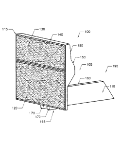
Disclosed herein is an embodiment of a roadside barrier to sit on top of a retaining wall to provide impact resistance to vehicular traffic. The precast concrete traffic barrier unit is designed to have a counterweight from soil backfill on the horizontal stem portion of the precast unit that acts to resist overturning pressures from vehicle impact on the precast traffic barrier portion which extends above the roadway surface. The horizontal stem is an exemplary designed triangular in shape to capture more of the backfill soil than typically what soil backfill rest directly above the horizontal stem or counterweight portion. Therefore, the triangular horizontal stem with its arching effect between adjacent units will allow more of the soil backfill to resist impact loading and reduce the amount of concrete needed to provide adequate vehicle restraint protection. An alignment seat locks the traffic barrier unit to the retaining wall below.


French Abstract

L'invention concerne un mode de réalisation d'une glissière de sécurité étant placée sur un mur de soutènement afin d'offrir une résistance aux impacts de circulation de véhicules. L'unité glissière de sécurité en béton prémoulé est conçue pour avoir un contrepoids grâce au sol de remblai sur la partie barre horizontale de l'unité prémoulée qui sert à résister aux pressions de retournement causées par un impact de véhicule sur la partie de la glissière de sécurité prémoulée qui s'étend au-dessus de la surface de la route. La barre horizontale est par exemple conçue pour être de forme triangulaire afin de capturer une plus grande partie de sol de remblai que le sol de remblai qui repose généralement directement au-dessus de la barre horizontale ou de la partie de contrepoids. De ce fait, la barre horizontale triangulaire ainsi que l'effet d'arc entre des unités adjacentes permet à une plus grande partie du sol de remblai de résister aux charges d'impact et réduit la quantité de béton nécessaire pour fournir une protection adéquate de retenue de véhicule. Un siège d'alignement immobilise l'unité glissière de sécurité sur le mur de soutènement en dessous.

Claims

Note: Claims are shown in the official language in which they were submitted.


- 7 -
CLAIMS

1. A precast traffic barrier configured for assembly on a top portion of an

underlying concrete earth retaining wall to prevent a vehicle traveling on a
roadway from
falling over the underlying concrete earth retaining wall, the precast traffic
barrier
comprising:
a front portion comprising an above-grade front surface, a below-grade front
surface, a rear surface, a top surface, a bottom surface, and a slanted
portion, the
slanted portion extending outwardly from the front portion and slanting
downwardly from
a portion of the rear surface;
a horizontal stem extending outwardly from the rear surface of the front
portion, the horizontal stem comprising a vertical center portion, a left
triangular
protrusion extending outwardly from a left side of the vertical center
portion, and a right
triangular protrusion extending outwardly from a right side of the vertical
center portion,
the left triangular protrusion and the right triangular protrusion sloping
downwardly from
the top surface of the horizontal step to a bottom surface of the horizontal
stem;
a diagonal portion connecting the slanted portion of the front portion to the
horizontal stem, wherein the diagonal portion traverses between the slanted
portion of
the front portion and the top surface of the horizontal stem, and wherein the
diagonal
portion transfers a cantilever pressure on the horizontal stem to the front
portion; and
an alignment seat extending along at least a portion of the horizontal
stem, the alignment seat engaged with the top portion of the underlying earth
retaining
wall.
2. The precast traffic barrier of claim 1, wherein the alignment seat
engages
at least:
the rear surface of the front portion;
a bottom surface of the left triangular protrusion; and
a bottom surface of the right triangular protrusion.
3. The precast traffic barrier of claim 1, wherein the alignment seat
comprises:
a left aligning element extending rearward along at least a portion of the
left triangular protrusion and downwardly from a bottom surface of the left
triangular
protrusion; and


- 8 -

a right aligning element extending rearward along at least a portion of the
right triangular protrusion and downwardly from a bottom surface of the right
triangular
protrusion.
4. The precast traffic barrier of claim 3, wherein the left aligning
element
comprises a left protruding lug and the right aligning element comprises a
right
protruding lug.
5. The precast traffic barrier of claim 3, wherein a front face of the left

aligning element is parallel with the rear surface of the front portion and a
front face of
the right aligning element is parallel with the rear surface of the front
portion.
6. A precast traffic barrier configured for assembly on a top portion of an

underlying concrete earth retaining wall, the precast traffic barrier
comprising:
a front portion comprising an above-grade front surface, a below-grade
front surface, a rear surface, a top surface, a bottom surface, and a slanted
portion, the
slanted portion extending outwardly from the front portion and slanting
downwardly from
a portion of the rear surface;
a horizontal cantilever triangular stem extending outwardly from the rear
surface of the front portion, the horizontal cantilever triangular stem
comprising at least a
left triangular protrusion, and a right triangular protrusion wherein:
the left triangular protrusion extends outwardly from a top left side
of a vertical center portion of the horizontal cantilever triangular stem and
slopes
downwardly from a top surface of the horizontal cantilever triangular stem to
a
bottom surface of the horizontal cantilever triangular stem; and
the right triangular protrusion extends outwardly from a top right
side of the vertical center portion of the horizontal cantilever triangular
stem and
slopes downwardly from a top surface of the stem to a bottom surface of the
horizontal cantilever triangular stem;
a diagonal portion that traverses between the slanted portion of
the front portion and the horizontal cantilever triangular stem and transfers
a
cantilever pressure on the horizontal cantilever triangular stem to the front
portion;
and
an alignment seat extending along at least a portion of the horizontal
cantilever triangular stem, the alignment seat connected to at least:
the top portion of the underlying earth retaining wall;


- 9 -

the rear surface of the front portion;
a bottom face of the left triangular protrusion; and
a bottom face of the right triangular protrusion.
7. The precast traffic barrier of claim 6, wherein the alignment seat
comprises at least a left lug aligned with the rear surface of the front
portion and a right
lug aligned with the rear surface of the front portion.
8. The precast traffic barrier of claim 6, wherein the vertical center
portion of
the horizontal cantilever triangular stem is at least 30 inches below a
roadway.
9. The precast traffic barrier of claim 1, wherein the diagonal portion is
nonparallel to the horizontal stem.
10. The precast traffic barrier of claim 1, wherein the diagonal portion is

nonparallel to the underlying concrete earth retaining wall.
11. The precast traffic barrier of claim 6, wherein the diagonal portion is

nonparallel to the horizontal cantilever triangular stem.
12. The precast traffic barrier of claim 6, wherein the diagonal portion is

nonparallel to the underlying concrete earth retaining wall.

Description

Note: Descriptions are shown in the official language in which they were submitted.


PRECAST TRAFFIC BARRIER ATOP RETAINING WALL SYSTEM
BACKGROUND
CROSS REFERENCE TO RELATED APPLICATIONS
[0001] This application claims priority to copending U.S. provisional
application
entitled "PRECAST TRAFFIC BARRIER ATOP RETAINING WALL SYSTEM" having
serial no. 61/665,545, filed June 28, 2012.
[0002] Conventional concrete earth retaining walls are commonly used for
architectural, site development and roadway/highway construction applications.

When roadways are located above or rest on top of the completed earth
retaining
wall, a traffic barrier is required to prevent vehicles from falling off of
the retaining
wall. Therefore, a traffic barrier is required to contain the impact from
vehicles to
keep them from falling over the retaining wall. The objective of the current
invention
is to minimize the concrete required for this purpose of using an exemplary
shaped
counterweight stem to capture more of the soil backfill weight located behind
the
earth retaining wall above the stem location to act as a counterweight and
prevent
barrier movement.
BRIEF DESCRIPTION OF THE DRAWINGS
[0003] Many aspects of the invention can be better understood with
reference to
the following drawings. The components in the drawings are not necessarily to
scale, emphasis instead being placed upon clearly illustrating the principles
of the
present invention. Moreover, in the drawings, like reference numerals
designate
corresponding parts throughout the several views.
[0004] Figure 1 is a view of the exemplary precast traffic barrier in
accordance
various embodiments of the disclosure;
- 1 -
CAN_DMS. \130770007\1
CA 2877714 2019-11-29

¨ 2 ¨
[0005] Figure 2 is a cross sectional view of an earth retaining wall
with the
exemplary precast traffic barrier sitting on top of an earth retaining wall in
accordance
various embodiments of the disclosure;
[0006] Figure 3 is an elevation view of an earth retaining wall with
the exemplary
precast traffic barrier making up the top row of precast concrete units in
accordance
various embodiments of the disclosure;
[0007] Figure 4 is a side view of the exemplary precast traffic barrier
in
accordance various embodiments of the disclosure;
[0008] Figure 5 is a top view of the exemplary precast traffic barrier
in
accordance various embodiments of the disclosure;
[0009] Figure 6 is a back view of the exemplary precast traffic barrier
in
accordance various embodiments of the disclosure.
DETAILED DESCRIPTION
[0010] Disclosed herein are different views of the exemplary precast
traffic
barrier related to the siting above an earth retaining wall to prevent traffic
from falling
over the earth retaining wall. Reference will now be made in detail to the
description
of the embodiments as illustrated in the drawings. Like reference numbers
indicate
like parts throughout the several views.
[0011] When roadways, driveways, or vehicle access is planned above an
underlying earth retaining wall, a traffic barrier to prevent traffic from
falling over the
walls leading edge is required. Traditionally, a guard rail or poured in place
concrete
traffic barrier is installed above the underlying earth retaining wall to
contain vehicles
traveling on the planned drive isle or roadway above the underlying earth
retaining
wall. The exemplary invention is to expedite installation of the traffic
barrier by
making it a part of the earth retaining wall system where the traffic barriers
can act as
CAN_DMS. \ 130770007 \ 1
CA 2877714 2019-11-29

¨ 3 ¨
the top row of the modular precast retaining wall system and provide
resistance to
overturning by using the backfill soil weight resting on the horizontal
cantilever
triangular stem. The downward pressure of the soil backfill beside and on top
of the
horizontal protruding stem provides the resisting pressure to have the
exemplary
precast traffic barrier act as a cantilever foundation with a vertical wall
and resist
impact loads from vehicles impacting the portion of the precast traffic
barrier
extending above grade.
[0012] Generally speaking, the portion of the precast traffic barrier
extending
above grade has a geometry and dimension defined by various state Department
of
Transportations that are standard or uniform throughout all traffic barriers
installed
along roadways, highways, and planned drive isles of the respective states.
Therefore, the geometry of the vertical portion of the precast traffic barrier
that
extends above the roadway grade may vary from state to state.
[0013] Referring to Figure 1, the exemplary precast traffic barrier 100
has a front
portion 115, a horizontal stem 190, and an alignment seat 165. The front
portion 115
has an above-grade front surface 130, a below-grade front surface 120, a top
surface
140, a rear surface 180, and a slanted portion 150. The above-grade front
surface
130 extends vertically above roadway grade and the below-grade front surface
120
extends vertically below roadway grade. The below-grade front surface 120
comprises the upper portion of the underlying earth retaining wall. The top
surface
140 of the front portion 115 is typically 32 to 36 inches above the roadway or

driveway surface elevation. The rear surface 180 of the front portion 115
extends
above grade. Vehicular impact would occur against the rear surface 180 as well
as
the slanted portion 150. The overall stability of the exemplary precast
traffic barrier
100 is prevented from overturning by a counterweight from backfill soil
resting beside
and above the horizontal stem 190. A protrusion 110 of the rear stem helps
capture
the surrounding backfill soils weight to add resisting force by means of
downward
CAN_DMS: \130770007\1
CA 2877714 2019-11-29

¨ 4 ¨
weight on the horizontal stem 190. The horizontal stem 190 extends from a top
surface 192 to a bottom surface 194. The vertical center portion 160 of the
horizontal
stem 190 is approximately 30 inches below the drive or roadway grade to allow
the
installation of utilities and pavement section not obscured by the precast
traffic barrier
100 piece or unit. To keep the exemplary precast traffic barrier from sliding
on top of
the retaining wall, an alignment seat 165 comprising aligning elements 170
extend
below the exemplary precast traffic barrier 100 to lock into the top concrete
precast
unit of the earth retaining wall. The aligning elements 170 may comprise, for
example, two protruding lugs.
[0014] Figure 2 shows a cross section 200 of the elevated roadway grade 220
sitting on top of the earth retaining wall. The horizontal stem 190 of the
exemplary
precast traffic barrier 100 sits well below the pavement grade 220 to prevent
interference.. For installation of the exemplary precast traffic barrier 100,
a square
hole 240 is cast into the exemplary precast traffic barrier 100 to facilitate
lifting and
hoisting into place. A diagonal portion 210 is required to transfer the
downward
cantilever pressure on the horizontal stem 190 to the front portion 115 of the

exemplary precast traffic barrier 100 to prevent impact on the rear surface
180 of the
barrier-facing vehicular traffic. The exemplary precast traffic barrier 100 is
aligned
with the underlying earth retaining wall by the alignment seat 165, which is
engaged
to a top portion of the underlying earth retaining wall.
[0015] Figure 3 shows an elevation view 300 of the front face of the
earth
retaining wall, the exemplary precast traffic barrier 100 makes up the top row
of the
concrete earth retaining wall to complete or top out the earth retaining wall
soil
retention requirements. The grade of the proposed roadway 220 is below the
barrier
portion of the precast traffic barrier 100 but above the horizontal cantilever
triangular
stem 105 of the precast traffic barrier 100.
CANI_DMS: \130770007\1
CA 2877714 2019-11-29

¨ 5 ¨
[0016] In Figure 4, the exemplary precast traffic barrier 100 is shown.
The
aligning elements 170 extend below the bottom of the horizontal stem 190 to
lock into
the earth retaining wall system below. The aligning elements 170 extend
downwardly
from the bottom surface 185 of the protrusion 110 of the horizontal stem 190
and
rearward along the protrusion 110 of the horizontal stem 190. The below-grade
front
surface 120 of the precast traffic barrier 100 is in vertical alignment with
the
underlying retaining wall face and the front face 175 of the aligning element
170 to
complete the earth retaining wall vertical plane alignment. For example, the
aligning
elements 170 may be aligned in a parallel fashion with the rear surface 180 of
the
front portion 115.
[0017] Figure 5 shows the top view to illustrate the triangular
protrusions 110 of
the horizontal stem 190 that cover approximately 50% of the overall
counterweight
area of backfill soil that is available to provide weight for overturning
resistance. The
triangular protrusions 110 allow the reduced horizontal coverage area and
hence
save precast concrete area and volume. The triangular protrusions 110 extend
outwardly from the top side 195 of the vertical center portion 160 of the
horizontal
stem 190 and slope downwardly from the top surface 192 of the horizontal stem
190
to the bottom surface 194 of the horizontal stem 190. The diagonal portion 210

connects the rear surface 180 with the vertical center portion 160 of the
horizontal
stem 190.
[0018] Figure 6 is a rear view of the exemplary precast traffic barrier
100 which
shows the diagonal portion 210 connecting the vertical center portion 160 of
the
horizontal stem 190 up to the vertical rear surface 180 of the front portion
115 of the
precast traffic barrier 100.
CAN_DMS: \13077000711
CA 2877714 2019-11-29

¨ 6 ¨
[0019] It should be emphasized that the above described invention of
the
present disclosure is to implement an arching effect within the earth
retaining wall
backfill soils by the triangular stem to take advantage of the soil backfill
vertical
weight to provide resisting force from horizontal vehicular impact on the
portion of the
stem above the drive isle or roadway grade. The dimensions of the portion of
the
barrier above grade may vary depending upon various Department of
Transportation
guidelines for impact barriers along roadways.
[0020] It should be emphasized that the above-described embodiments of the
present invention, particularly, any "preferred" embodiments, are merely
possible
non-limiting examples of implementations, merely set forth for a clear
understanding
of the principles of the invention. Many variations and modifications may be
made to
the above-described embodiment(s) of the invention without departing
substantially
from the spirit and principles of the invention. All such modifications and
variations
are intended to be included herein within the scope of this disclosure and the
present
invention.
CAN_DMS: \130770007 \ 1
CA 2877714 2019-11-29

Representative Drawing
A single figure which represents the drawing illustrating the invention.
Administrative Status

For a clearer understanding of the status of the application/patent presented on this page, the site Disclaimer , as well as the definitions for Patent , Administrative Status , Maintenance Fee  and Payment History  should be consulted.

Administrative Status

Title Date
Forecasted Issue Date 2020-06-30
(86) PCT Filing Date 2013-06-27
(87) PCT Publication Date 2014-01-03
(85) National Entry 2014-12-22
Examination Requested 2018-06-21
(45) Issued 2020-06-30

Abandonment History

There is no abandonment history.

Maintenance Fee

Last Payment of $263.14 was received on 2023-06-23


 Upcoming maintenance fee amounts

Description Date Amount
Next Payment if small entity fee 2024-06-27 $125.00
Next Payment if standard fee 2024-06-27 $347.00

Note : If the full payment has not been received on or before the date indicated, a further fee may be required which may be one of the following

  • the reinstatement fee;
  • the late payment fee; or
  • additional fee to reverse deemed expiry.

Patent fees are adjusted on the 1st of January every year. The amounts above are the current amounts if received by December 31 of the current year.
Please refer to the CIPO Patent Fees web page to see all current fee amounts.

Payment History

Fee Type Anniversary Year Due Date Amount Paid Paid Date
Application Fee $400.00 2014-12-22
Maintenance Fee - Application - New Act 2 2015-06-29 $100.00 2014-12-22
Registration of a document - section 124 $100.00 2016-01-29
Maintenance Fee - Application - New Act 3 2016-06-27 $100.00 2016-06-01
Maintenance Fee - Application - New Act 4 2017-06-27 $100.00 2017-05-30
Maintenance Fee - Application - New Act 5 2018-06-27 $200.00 2018-05-30
Request for Examination $800.00 2018-06-21
Maintenance Fee - Application - New Act 6 2019-06-27 $200.00 2019-05-31
Final Fee 2020-06-03 $300.00 2020-04-16
Maintenance Fee - Application - New Act 7 2020-06-29 $200.00 2020-06-19
Maintenance Fee - Patent - New Act 8 2021-06-28 $204.00 2021-06-18
Maintenance Fee - Patent - New Act 9 2022-06-27 $203.59 2022-06-17
Maintenance Fee - Patent - New Act 10 2023-06-27 $263.14 2023-06-23
Owners on Record

Note: Records showing the ownership history in alphabetical order.

Current Owners on Record
EARTH WALL PRODUCTS, LLC
Past Owners on Record
EARTH REINFORCEMENT TECHNOLOGIES, LLC.
Past Owners that do not appear in the "Owners on Record" listing will appear in other documentation within the application.
Documents

To view selected files, please enter reCAPTCHA code :


To view images, click a link in the Document Description column. To download the documents, select one or more checkboxes in the first column and then click the "Download Selected in PDF format (Zip Archive)" or the "Download Selected as Single PDF" button.

List of published and non-published patent-specific documents on the CPD .

If you have any difficulty accessing content, you can call the Client Service Centre at 1-866-997-1936 or send them an e-mail at CIPO Client Service Centre.


Document
Description 
Date
(yyyy-mm-dd) 
Number of pages   Size of Image (KB) 
Amendment 2019-11-29 24 878
Description 2019-11-29 6 211
Claims 2019-11-29 3 106
Final Fee 2020-04-16 5 144
Representative Drawing 2020-06-02 1 17
Cover Page 2020-06-02 1 52
Abstract 2014-12-22 1 77
Claims 2014-12-22 3 88
Drawings 2014-12-22 6 80
Description 2014-12-22 6 201
Representative Drawing 2014-12-22 1 31
Cover Page 2015-02-20 1 54
Request for Examination 2018-06-21 2 72
Examiner Requisition 2019-05-31 5 242
PCT 2014-12-22 14 515
Assignment 2014-12-22 5 187