Note: Descriptions are shown in the official language in which they were submitted.
CA 02877773 2014-12-23
1
Wheelchair
The invention relates to a wheelchair, especially a wheelchair with an
additional auxiliary drive means.
A conventional wheelchair comprises a chair frame with a seating area
between two large drive wheels, as well as two smaller auxiliary wheels and
foot rests in front of them. The drive wheels are on their outer side provided
with a drive ring, which in turn is connected to the wheel rim. The drive
rings
are rotated with the hands, allowing independent locomotion without third
party.
Since this locomotion requires a high degree of effort, a drive was proposed
in
DE-U 202010005729, which would allow a power-saving and safe handling.
This is done by a drive lever which is hinged to the wheel axles of the drive
wheels and can be swung back and forth about the wheel axis. The drive
levers reach out over the radius of the drive wheel and are provided with a
handle and a brake. The pivotal movement of a drive lever is limited by a
extension arm guided in a longitudinal slot of a protection plate.
In DE-U-202008017474, a drive motor is arranged in the axis of the drive
wheels, to support the manual driving force, wherein a control device is
provided, which comprises an anti-back-roll mode of operation.
In a similar solution according to DE-U-202007008736, each drive wheel is
part of a drive wheel module with a drive power unit arranged in the body
frame of the wheelchair, in order to minimize the width of the wheelchair.
In order to move forward, the person seated in the wheelchair must use at
least one hand to rotate a drive ring of a drive wheel and / or operate the
control device of a drive power unit.
It is therefore an object of the invention, to avoid the disadvantages of the
prior art and to propose a wheelchair, notably to a wheelchair with an
CA 02877773 2014-12-23
2
additional auxiliary drive means, which may also allow movement of the
wheelchair without using the hands.
This problem is solved with the features of claim 1. A conventional wheelchair
comprises a seat tiltable along the axle of the drive wheels in the direction
of
the drive wheels and / or transverse thereto, wherein the tilting axis of the
seat is located centrally between the drive wheels and above the wheel axle.
Preferably, the seat is connected to the wheel shaft of the drive wheels by
lever joints, tooth rack / gear drives or thereto similar drives. The drive
can
also be supplemented with an electric drive, an air motor or thereto similar
drives.
If the tilting movement is perpendicular to the axle of the drive wheels, the
backrest may also be designed tiltable, similar to handcars or draisines.
Further preferred embodiments are disclosed in the dependent claims. Thus,
the wheelshaft can be designed as a crankshaft, with its deflection preferably
formed at an angle or being curved in order to avoid dead spots, or it
comprises a cam-follower arrangement.
Each drive wheel comprises a standard drive ring and / or a drive lever.
When using toothed rack / gear drives, the wheel shaft is straight, the levers
are designed as toothed racks and on each side on the wheel shaft even
stepped gears can be arranged next to each other, so that there is a gear
shift. Likewise, the seat bottom could be constructed as a gear segment,
corresponding with a horizontally arranged toothed rack whose ends are in
turn connected to levers or tooted racks.
By means of the invention, a wheelchair can be moved by a tilting movement
of the seat transverse to the direction of travel so that the hands remain
free
e.g. for a ball game or another activity, or even disabled hands do not
represent a problem. Such a wheelchair is also suitable for driving backwards.
The mobility of the wheelchair user is thus considerably extended.
CA 02877773 2014-12-23
3
This type of lever joints or crank-rocker mechanisms are in principle known
from handcars or draisines. In DE-A-3201310, for example, a drive device for
bicycles with lever joints is described. On both sides of the bike such a
drive
device is mounted to avoid a dead spots when using the pedals.
In any case, the actuation of the lever joints or the crank-rocker mechanisms
is performed solely by hand or leg movements. Alternatively or in addition,
several drives are conceivable, e.g. electric drives.
It is possible to transfer the tiltable seat and the drive according to the
invention to bicycles. Thereby, a supplementary drive acting on the rear wheel
would be achieved by tilting the seat, while keeping the pedal and chain
drive.
An embodiment of the invention will now be described closer with reference to
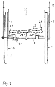
a drawing. The figures show: Fig. 1: a wheelchair with an auxiliary drive
arrangement. Fig. 2: a detailed view of the auxiliary drive arrangement.
A conventional wheelchair comprises an only indicated chair frame 1 with a
seating area 2 between two large drive wheels 3, as well as two conventional
smaller auxiliary wheels and foot rests (not shown) in front of them. The
drive
wheels 3 are on their outer side provided with a drive ring 4, which in turn
is
connected to the wheel rim 5. The drive rings 4 can be rotated with the hands
of the seated person 10 allowing an independent locomotion without third
party.
Additionally, drive levers 7 are mounted outside to the wheel axles 6 of the
drive wheels 3, pivotable back and forth about the wheel axles or designed as
is as crank-rocker mechanism. The drive levers 7 reach out over the radius of
the drive wheel 3 and are provided with a handle 8. The seating area 2 is
arranged on a pivot bearing 21 above the crank-rocker-mechanism-like wheel
shaft 9 in an articulatable or tiltable manner with respect to the wheel axles
6.
On each outer portions 23 of the seating area 2 opposite the respective drive
wheel 3 a lever 22 is hinged, being pivotably connected to a deflection 91 of
the wheel shaft 9. The deflection 91 formed at an angle or curved.
CA 02877773 2014-12-23
4
If the outer portion 23 is tilted downwards due to a tilting movement
triggered
by a driving person, the hinged lever 22 is pressed downwards, resulting in a
rotation of the wheel shaft 9 and thereby the drive wheels 3, caused by the
deflection 91. At the same the other lever 22 is pulled upwards. A subsequent
tilting movement of the seating area 2 in the opposite direction presses the
other lever 22 downwards and causes further rotation of the wheel shaft 9.
The wheelchair is driven by the tilting motion of the seating area 2 and is
controlled by the speed differences on the driving wheels 3. The wheelchair
can be driven forwards and backwards in driving direction and can overcome
slopes of up to 20 degrees.
Normal wheel parking brakes are used as a roll-away protection. A service
brake is provided by actuation of the hand lever (drive lever 7) and/or a
movement of the back. A pressure point against accidental actuation is
possible, as well as recuperation of braking energy.
List of Reference Signs
1 chair frame
2 seating area
3 drive wheel
4 drive ring
5 wheel rim
6 wheel axle
7 drive lever
8 handle
9 wheel shaft
10 person
21 pivot bearing
22 lever
CA 02877773 2014-12-23
23 outer portion
91 deflection