Note: Descriptions are shown in the official language in which they were submitted.
ACTUATOR APPARATUS HAVING INTERNAL PASSAGEWAYS
FIELD OF THE DISCLOSURE
[0001]The present disclosure relates generally to actuators and, more
specifically, to
actuator apparatus having internal passageways.
BACKGROUND
[0002] Control valves are commonly used in process control systems to control
the
flow of process fluids. A control valve typically includes an actuator (e.g.,
a
pneumatic actuator, a hydraulic actuator, etc.) operatively coupled to a flow
control
member of a fluid valve to automate the control valve. In operation, a
controller
(e.g., a positioner) is often employed to supply a control fluid (e.g., air)
to the
actuator which, in turn, positions the flow control member (e.g., a valve
gate, a plug,
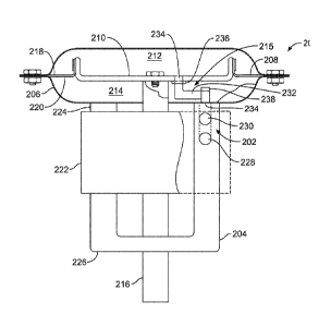
a closure member, etc.) to a desired position relative to a valve seat to
control or
regulate the fluid flow through the valve.
[0003] In some examples, a yoke may be employed to couple the actuator to the
fluid
valve. Additionally, in some instances, the controller may be mounted to the
yoke.
In some examples, external tubing may be employed to fluidly couple a control
fluid
between the controller and a chamber (e.g., a pressure chamber) of the
actuator.
However, the external tubing may become damaged or dislodged, thereby
affecting
the accuracy of the actuator and, thus, a desired fluid flow through the
valve. In
other examples, an internal pathway may be defined within the yoke to fluidly
couple
a control fluid between a controller and a lower pressure chamber of an
actuator.
However, in these examples, external tubing is required to fluidly couple the
control
fluid between the controller and an upper pressure chamber of the actuator.
SUMMARY
[0004] According to one aspect of the present disclosure, an object is to
provide an
apparatus, comprising:
1
CA 2877934 2019-11-21
an actuator casing having a load apparatus to define an upper pressure
chamber and a lower pressure chamber, the upper pressure chamber being
opposite the lower pressure chamber;
a yoke to couple the actuator casing to a fluid valve;
an internal passageway formed in a body of the yoke to fluidly couple a
control fluid to at least one of the upper pressure chamber or the lower
pressure
chamber;
a fluid connector assembly positioned in the actuator casing to fluidly couple
the internal passageway to the upper pressure chamber, the load apparatus
being
positioned between the internal passageway of the yoke and the upper pressure
chamber; and
a positioner mountable to the yoke, wherein the positioner is to supply the
control fluid to the internal passageway, and wherein an outlet of the
positioner is
coupled to an inlet of the internal passageway when the positioner is mounted
to the
yoke.
[0004a] According to another aspect of the present disclosure, an object is to
provide
an actuator apparatus, comprising:
a first end to couple to a casing of an actuator;
a second end to couple to a fluid valve; and
a first fluid path formed in a yoke between the first end and the second end,
the first fluid path having a first outlet positioned adjacent the first end
of the yoke
and a first inlet positioned between the first end and the second end, the
first fluid
path to fluidly couple to an upper pressure chamber of the actuator; and
a second fluid path formed in the yoke between the first end and the second
end, the second fluid path having a second outlet positioned adjacent the
first end of
the yoke and a second inlet positioned between the first end and the second
end,
the second fluid path to fluidly couple to a lower pressure chamber of the
actuator.
la
CA 2877934 2019-11-21
[0004b] Other possible aspect(s), object(s), embodiment(s), variant(s) and/or
advantage(s) of the present disclosure, all being preferred and/or optional,
are briefly
summarized hereinbelow.
[0005] Indeed, an example apparatus includes an actuator casing having a load
apparatus to define an upper pressure chamber and a lower pressure chamber.
The
upper pressure chamber is opposite the lower pressure chamber. A yoke is to
couple the actuator casing to a fluid valve. An internal passageway is formed
in a
body of the yoke to fluidly couple a control fluid to at least one of the
upper pressure
chamber or the lower pressure chamber. A fluid connector assembly is
positioned in
the actuator casing to fluidly couple the internal passageway to the upper
pressure
chamber. The load apparatus is positioned between the internal passageway of
the
yoke and the upper pressure chamber.
[0005e] An actuator apparatus includes a first end to couple to a casing of an
actuator and a second end to couple to a fluid valve. A first fluid path is
formed in
the yoke between the
lb
CA 2877934 2019-11-21
CA 02877934 2014-12-23
WO 2014/011721 PCMJS2013/049840
first end and the second end. The first fluid path has a first outlet
positioned adjacent the first
end of the yoke and a first inlet positioned between the first end and the
second end. The first
fluid path is to fluidly couple to an upper pressure chamber of the actuator.
A second fluid
path is formed in the yoke between the first end and the second end. The
second fluid path
has a second outlet positioned adjacent the first end of the yoke and a second
inlet positioned
between the first end and the second end. The second fluid path is to fluidly
couple to a
lower pressure chamber of the actuator.
[0006] Another example apparatus includes means for actuating a fluid valve
and means for
attaching the means for actuating to a fluid valve. The example apparatus
includes first
means for fluidly coupling a control fluid to a first fluid chamber of the
actuator casing. The
first means for fluidly coupling is integrally formed with the means for
attaching and
provides the control fluid to the first fluid chamber without the use of
external tubing. The
example apparatus includes second means for fluidly coupling the control fluid
to a second
fluid chamber of the actuator casing. The second means for fluidly coupling is
positioned at
least partially in the first fluid chamber.
BRIEF DESCRIPTION OF THE DRAWINGS
[0007] FIGS. lA and 1B illustrate a known control valve having external
tubing.
[0008] FIG. 2 illustrates an example actuator assembly disclosed herein having
an internal
passageway in accordance with the teachings disclosed herein.
[0009] FIGS. 3A and 3B illustrate an example yoke of the example actuator
assembly of FIG.
2.
[0010] FIGS. 4A and 4B illustrate another example yoke disclosed herein having
an internal
passageway.
[0011] FIG. 5 illustrates another example actuator assembly disclosed herein
having an
internal passageway.
[0012] FIG. 6 illustrates another example actuator assembly disclosed herein
having an
internal passageway.
[0013] FIG. 7 illustrates another example actuator disclosed herein having an
internal
passageway.
- 2 -
CA 02877934 2014-12-23
WO 2014/011721 PCT/US2013/049840
DETAILED DESCRIPTION
[0014] Example actuator assemblies disclosed herein eliminate the need to
employ external
tubing to fluidly couple a control fluid between a positioner or controller
and a chamber (e.g.,
a pressure chamber) of an actuator. In particular, example actuators disclosed
herein employ
a yoke to fluidly couple a supply or control fluid between a positioner and a
chamber (e.g., a
pressure chamber) of an actuator.
[0015] More specifically, example yoke apparatus disclosed herein employ one
or more
internal passageways formed in a body of the yoke to fluidly couple a control
fluid (e.g.,
pneumatic air) between the positioner and at least one of an upper pressure
chamber and a
lower pressure chamber of the actuator. In addition, an example actuator
assembly disclosed
herein employs a fluid connector assembly to fluidly couple the one or more
internal
passageways to the other one of the upper and lower pressure chambers. In this
manner, the
positioner may be fluidly coupled to the upper and lower pressure chambers of
the actuator
without the use of external tubing. In other words, the actuator assembly
disclosed herein
does not employ tubing external to a surface of the yoke and/or an actuator
casing between a
position and an actuator. To fluidly couple the positioner to the upper and
lower pressure
chambers, a positioner may be coupled or mounted to a yoke (e.g., an outside
surface of the
yoke) via, for example, a bracket. In turn, the one or more internal
passageways formed in
the body of the yoke fluidly couple an outlet port of the positioner to one or
more pressure
chambers of an actuator assembly. Eliminating external tubing significantly
reduces or
eliminates damage to external tubing that may otherwise occur, thereby
increasing the
accuracy and reliability of the example actuator assemblies disclosed herein.
[0016] Before describing the example actuators in greater detail, a brief
discussion of a
known control valve assembly 100 is provided in connection with FIGS. lA and
1B.
Referring to FIGS. lA and 1B, the control valve assembly 100 includes an
actuator 102
coupled to a fluid valve 104 via a yoke 106. As shown in FIG. 1B, a diaphragm
108 is
disposed in an actuator casing 110 to define an upper pressure chamber 112 and
a second
pressure chamber 114. A positioner 116 (FIG. 1A) provides a control fluid
(e.g., pneumatic
air) to the upper and lower pressure chambers 112 and 114. More specifically,
external
tubing 118a and 118b is employed to fluidly couple the control fluid between
the positioner
116 and the pressure chambers 112 and 114, respectively.
[0017] In operation, the positioner 116 provides a control fluid from a
pressure source 120 to
the upper pressure chamber 112 and/or a second pressure chamber 114 to provide
a pressure
differential across the diaphragm 108. Such pressure differential cause the
diaphragm 108 to
- 3 -
CA 02877934 2014-12-23
WO 2014/011721 PCT/US2013/049840
move a valve plug operatively coupled to the diaphragm 108 in a rectilinear
path relative to a
valve seat (not shown) to control fluid flow through the fluid valve 104.
[0018] However, the external tubing 118a and 118b may become damaged or
dislodged,
thereby restricting or preventing the control fluid from flowing between the
positioner 116
and/or the upper and lower pressure chambers 112 and 114. Such damage or
dislodgment to
the external tubing 118a and/or 118b may be caused by contact with an object,
such as a
vehicle. In some instances, a process fluid flowing through the fluid valve
104 may impart a
frequency to the control valve assembly 100 that is substantially equal to a
resonant
frequency of the actuator 102 and/or the control valve assembly 100, causing
the actuator 102
and/or the control valve assembly 100 and, thus, the tubing 118a and/or 118b
to vibrate. In
some such instances, for example, the induced vibrations may cause the
external tubing 118a
and l 18b to become dislodged or damaged, thereby affecting the operation of
the actuator
102 and, thus, the accuracy of the position of a flow control member relative
to the valve seat.
[0019] FIG. 2 illustrates an example actuator assembly 200 having an internal
passageway
202 in accordance with the teachings disclosed herein. The example actuator
assembly 200
of FIG. 2 includes a yoke 204 to couple an actuator casing 206 to a fluid
valve (e.g., the fluid
valve 104 of FIG. 1A). The actuator assembly 200 employs a load apparatus or a
diaphragm
208 positioned in the actuator casing 206 to define an upper pressure chamber
212 and a
lower pressure chamber 214 , the upper pressure chamber 212 being opposite the
second
pressure chamber 214.
[0020] More specifically and as described below, the actuator assembly 200
employs a fluid
connector assembly 215 to enable the internal passageway 202 to be fluidly
coupled to both
and/or either of the upper and lower pressure chambers 212 and 214. In this
manner, the
internal passageway 202 and the fluid connector assembly 215 provide a fluid
connection to
the actuator casing 206 without use of tubing externally positioned relative
to the yoke 204
and/or the actuator assembly 200 (e.g., a passageway adjacent an outer surface
of the yoke
204 of the actuator assembly 200).
[0021] In this example, the diaphragm 208 is coupled to an actuator stem 216
via a
diaphragm plate 210. For example, the diaphragm 208 is fixedly attached,
clamped, fastened
or otherwise coupled to the diaphragm plate 210 (e.g., via a clamp and/or a
fastener). The
actuator stem 216, in turn, operatively couples a flow control member of a
fluid valve and the
diaphragm 208. Additionally, the upper pressure chamber 212 is in fluid
communication
with a first side 218 of the diaphragm 208 and the lower pressure chamber 214
is in fluid
communication with a second side 220 of the diaphragm 208.
- 4 -
CA 02877934 2014-12-23
WO 2014/011721 PCT/US2013/049840
[0022] As shown in FIG. 2, a positioner 222 is coupled or mounted to the yoke
204. For
example, the positioner 222 may be mounted to the yoke 204 via a bracket
assembly (not
shown). The bracket assembly may include, for example, a bracket or plate
having multiple
apertures to receive fasteners. For example, at least one fastener extends
through one of the
apertures of the bracket to engage to the yoke 204.
[0023] The yoke 204 of the illustrated example has a first end 224 that
couples to the actuator
casing 206 and a second end 226 that couples to, for example, a bonnet of a
fluid valve.
Additionally, the internal passageway 202 fluidly couples the positioner 222
and the actuator
assembly 200 and/or the casing 206. In other words, the internal passageway
202 fluidly
couples a control fluid to at least one of the upper pressure chamber 212 or
the lower pressure
chamber 214 (e.g., adjacent an outer surface of the yoke 204 of the actuator
assembly 200).
More specifically, the internal passageway 202 is integrally formed with the
yoke 204. In the
illustrated example, the internal passageway 202 defines a first fluid path
228 and a second
fluid path 230. In particular, the first fluid path 228 fluidly couples the
positioner 222 (e.g., a
first outlet port of the positioner 222) or the control fluid to the upper
pressure chamber 212,
and the second fluid path 230 fluidly couples the positioner 222 (e.g., a
second outlet port of
the positioner 222) or the control fluid to the lower pressure chamber 214.
[0024] Additionally, the fluid connector assembly 215 employs a first fluid
passageway 232
to fluidly couple the first fluid path 228 and the upper pressure chamber 212.
The first fluid
passageway 232 is positioned in the lower pressure chamber 214 of the actuator
casing 206.
To fluidly couple the first fluid passageway 232 and the upper pressure
chamber 212, an
opening is formed in the diaphragm 208 and/or the diaphragm plate 210 to
establish fluid
communication between the first fluid passageway 232 and the upper pressure
chamber 212.
In particular, the first fluid passageway 232 of the illustrated example is
coupled to the
opening 234 via a connector 236 (e.g., a hose fitting or clamp).
[0025] Further, to accommodate for movement of the diaphragm 208, the first
fluid
passageway 232 of the illustrated example is formed of flexible tubing and has
a sufficient
length to prevent interference with the operation of the actuator assembly 200
and/or the
diaphragm 208 when the actuator assembly 200 moves between a first position to
allow fluid
flow through the valve (e.g., an open position of the valve) and a second
position to restrict
fluid flow through the valve (e.g., a closed position of the valve). As a
result, the
combination of the first fluid passageway 232 and the first fluid path 228
eliminates the need
to employ external tubing (e.g., the external tubing 118a of FIG. 1A) between
the positioner
222 and the upper pressure chamber 212.
- 5 -
CA 02877934 2014-12-23
WO 2014/011721 PCT/US2013/049840
[0026] Additionally, the second fluid path 230 is fluidly coupled to the lower
pressure
chamber 214 via a connector 238 (e.g., a hose fitting or clamp), thereby
eliminating the need
to employ external tubing (e.g.. the external tubing 118b of FIG. 1A) between
the positioner
222 and the lower pressure chamber 214. As a result, the example yoke 204 and
the fluid
connector assembly 215 significantly increase the reliability of the actuator
assembly 200 by
significantly reducing or eliminating damage that may otherwise occur if
external tubing is
employed.
[0027] FIG. 3A is a front view of the example yoke 204 of FIG. 2. FIG. 3B is a
plan view of
the example yoke 204 of FIG. 2. Referring to FIGS. 3A and 3B, the yoke 204 of
the
illustrated example has a body 300 (e.g., a U-shaped body) that defines a
first leg 302 and a
second leg 304. The first fluid path 228 has a first inlet 306 (FIG. 3A) and a
first outlet 308
(FIG. 3B) and the second fluid path 230 has a second inlet 310 (FIG. 3A) and a
second outlet
312 (FIG. 3B). In particular, in the illustrated example, the inlet 306 of the
first fluid path
228 is positioned between the first end 224 of the yoke 204 and the second end
226 of the
yoke 204 and the outlet 308 of the first fluid path 228 is positioned adjacent
the first end 224
of the yoke 204. More specifically, the first outlet 308 is positioned
relative to a surface 314
(e.g., a top or upper surface) of the first leg 302 of the yoke 204 and the
inlet 306 is
positioned relative to a surface 316 (e.g., a side surface) of the first leg
302 of the yoke 204.
In other words, the surface 314 is substantially perpendicular relative to the
surface 316 of the
yoke 204. As a result, a first portion 318 of the first fluid path 228 defines
a first axis 320
and a second portion 322 of the first fluid path 228 defines a second axis 324
such that the
first axis 320 is non-parallel relative to the second axis 324. In this
manner. the first portion
318 of the first fluid path 228 intersects the second portion 322 of the first
fluid path 228.
[0028] Also, the inlet 310 of the second fluid path 230 is positioned between
the first end 224
of the yoke 204 and the second end 226 of the yoke 204, and the outlet 312 of
the second
fluid path 230 is positioned adjacent the first end 224. More specifically,
the second outlet
312 is positioned on the surface 314 of the yoke 204 and the second inlet 310
is positioned on
the surface 316. As a result, a first portion 326 of the second fluid path 230
defines a first
axis 328 and a second portion 330 defines a second axis 332 such that the
first axis 328 of the
second fluid path 230 is non-parallel relative to the second axis 332 of the
second fluid path
230. In this manner, the first portion 326 of the second fluid path 230
intersects the second
portion 330 of the second fluid path 230.
[0029] In the illustrated example, the first leg 302 defines the first and
second fluid paths 228
and 230. In particular, the first fluid path 228 is adjacent the second fluid
path 230.
- 6 -
CA 02877934 2014-12-23
WO 2014/011721 PCT/US2013/049840
However, although the first fluid path 228 is adjacent the second fluid path
230, the first fluid
path 228 is fluidly isolated relative to the second fluid path 230. Thus, the
control fluid in the
first fluid path 228 cannot communicate (e.g., mix) with the control fluid in
the second fluid
path 230.
[0030] In other examples as described below, the first fluid path 228 may be
formed in the
first leg 302 of the yoke 204 and the second fluid path 230 may be formed in
the second leg
304 of the yoke. Additionally, in some examples, the yoke 204 may only employ
a single
fluid path 228 or 230. In yet other examples, the yoke 204 may employ more
than two fluid
paths. For example, to increase response time, each of the first and second
legs 302 and 304
may include the first and second fluid paths 228 and 230.
[0031] The yoke 204 of the illustrated example may be formed via, for example,
casting or
any other manufacturing process. Further, the first fluid path 228 and/or the
second fluid
path 230 may be formed via secondary manufacturing operations such as, for
example,
boring, drilling and/or any other suitable manufacturing process(es).
[0032] In operation, referring to FIGS. 2, 3A, and 3B, the positioner 222
receives a control
fluid from a supply source (e.g., the supply source 120 of FIG. 1A). The
positioner 222
regulates the control fluid and provides the control fluid to at least one of
the upper pressure
chamber 212 and/or the lower pressure chamber 214. In particular, a first
outlet or port of the
positioner 222 is coupled to the first inlet 306 of the first fluid path 228
and a second outlet or
port of the positioner 222 is coupled to the second inlet 310 of the second
fluid path 230. The
first fluid path 228 fluidly couples to the upper pressure chamber 212 and the
second fluid
path 230 fluidly couples to the lower pressure chamber 214.
[0033] In particular, the positioner 222 provides the control fluid to at
least one of the upper
pressure chamber 212 and/or the lower pressure chamber 214 to create a
pressure differential
across the diaphragm 208 to control fluid flow through a valve. For example, a
pressure of
the control fluid in the upper pressure chamber 212 that is greater than a
pressure of the
control fluid in the lower pressure chamber 214 provides a pressure
differential to cause the
diaphragm 208 to move in a first rectilinear path (e.g., a downward direction
in the
orientation of FIG. 2). Likewise, a pressure of the control fluid in the upper
pressure
chamber 212 that is less than the pressure of the control fluid in the lower
pressure chamber
214 provides a pressure differential to cause the diaphragm 208 to move in a
second
rectilinear path (e.g., an upward direction in the orientation of FIG. 2)
opposite the first
rectilinear path. Such rectilinear movement of the diaphragm 208 positions a
flow control
- 7 -
CA 02877934 2014-12-23
WO 2014/011721 PCT/US2013/049840
member of a valve relative to a valve seat to regulate the fluid flow through
a valve (e.g., the
fluid valve 106 of FIG. 1A).
[0034] FIGS. 4A and 4B illustrate another example yoke 400 having an internal
passageway
402 disclosed herein. More specifically, the internal passageway 402 defines a
first fluid path
404 and a second fluid path 406. The first fluid path 404 is fluidly isolated
relative to the
second fluid path 406. The yoke 400 of the illustrated example has a body 408
(e.g., a U-
shaped body) that defines a first leg 410 and a second leg 412. Referring to
FIGS. 4A and
4B, the first fluid path 404 is formed in the first leg 410 and the second
fluid path 406 is
formed in the second leg 412. The first and second fluid paths 404 and 406 are
configured
similar to the example fluid paths 228 and 230 described above in connection
with FIGS. 3A
and 3B.
[0035] FIGS. 5-7 illustrate other example actuators 500, 600. and 700
disclosed herein
having an example yoke similar to the example yoke 204 of FIGS. 2, 3A. and 3B.
Those
components of the example actuators 500, 600, and 700 that are substantially
similar or
identical to the components of the example yoke 204 or the actuator assembly
200 described
above and have functions substantially similar or identical to the functions
of those
components will not be described in detail again below. Instead, the
interested reader is
referred to the above corresponding descriptions. To facilitate this process,
the same
reference numbers will be used for like structures.
[0036] The example actuator 500 of FIG. 5 employs a yoke 204 to couple the
actuator casing
206 to a fluid valve (e.g. the fluid valve 106 of FIG. 1A). The actuator 500
has the load
apparatus or diaphragm 208 disposed in the actuator casing 206 to define a
lower pressure
chamber or fluid chamber 502 and an upper pressure chamber or spring chamber
504. A
spring 506 is disposed within the spring chamber 504 and imparts a bias or
force to the first
side 218 of the diaphragm 208. Additionally, the fluid chamber 502 is in fluid
communication with the second side 220 of the diaphragm 208.
[0037] In the illustrated example, the second fluid path 230 of the yoke 204
is fluidly coupled
to the fluid chamber 502. As shown, the example actuator 500 employs a plug,
cap or insert
508 to block or prevent fluid flow between the pressure chamber 502 and the
spring chamber
504 via an opening 234 of the diaphragm plate 210 and/or the diaphragm 208.
Additionally,
as shown, a removable plug, cap, or insert 510may be coupled to the first
inlet 306 of the first
fluid path 228 to prevent or restrict fluid communication to the spring
chamber 504 via the
first inlet 306. In some examples, the insert 510 may be removed from the
first inlet 306 to
- 8 -
CA 02877934 2014-12-23
WO 2014/011721 PCT/US2013/049840
fluidly couple (e.g., vent) the spring chamber 504 to atmosphere when an
outlet port of the
positioner 222 is not coupled to the first fluid path 228.
[0038] In operation, a positioner (e.g., the positioner 222 of FIG. 2)
supplies the control fluid
to the fluid chamber 502 via the second fluid path 230 to create a pressure
differential across
the diaphragm 208 to control a fluid flow through the fluid valve (e.g., the
fluid valve 106 of
FIG. 1A). For example, a pressure of the control fluid provided in the fluid
chamber 502 that
imparts a force on the second side 220 of the diaphragm 208 that is greater
than the force
imparted to the first side 218 by the spring 506 causes the diaphragm 208 to
move in a first
rectilinear path. Likewise, a pressure provided in the fluid chamber 502 that
imparts a force
to the second side 220 of the diaphragm 208 that is less than the force
imparted to the first
side 218 by the spring 506 causes the diaphragm 208 to move in a second
rectilinear path
opposite the first path.
[0039] FIG. 6 illustrates another example actuator 600 employing the example
yoke 204
disclosed herein. In this example, the first fluid path 228 of the yoke 204
fluidly couples a
control fluid from a positioner (e.g., the positioner 222 of FIG. 2) to an
upper pressure
chamber or fluid chamber 602 of the actuator 600. The fluid chamber 602 is in
fluid
communication with the first side 218 of the diaphragm 208. A spring 604 is
disposed within
a lower pressure chamber or spring chamber 606 of the actuator 600 and imparts
a force to
the second side 220 of the diaphragm 208. Additionally, the first fluid
passageway 232 of the
fluid connector assembly 215 is positioned in the spring chamber 606. The
first fluid
passageway 232 is coupled to the opening 234 of the diaphragm 208 and the
diaphragm plate
210 via the connector 236 to fluidly couple the first fluid path 228 and the
fluid chamber 602.
The first fluid passageway 232 may be implemented using tubing and, in
operation, does not
interfere with the spring 604. In particular, the first fluid passageway 232
is positioned
within a central opening 608 defined by the spring 604. In this example, the
second fluid
path 230 may be closed via, for example, the removable plug, cap, or insert
510.
Alternatively, the insert 510 may be removed to fluidly couple (e.g., vent)
the spring chamber
606 to atmosphere.
[0040] FIG. 7 illustrates yet another example actuator 700 employing a yoke
204 to couple
an actuator casing 206 to a fluid valve. In this example, the load apparatus
is a piston 702
disposed in the actuator casing 206 to define an upper pressure chamber 704
and a lower
pressure chamber 706. The upper pressure chamber 704 is in communication with
a first
side 708 of the piston 702 and the second pressure chamber 706 is in
communication with a
second side 710 of the piston 702. Additionally, the first fluid path 228
fluidly couples the
- 9 -
CA 02877934 2014-12-23
WO 2014/011721 PCT/US2013/049840
control fluid from a positioner to the upper pressure chamber 704 and the
second fluid path
230 fluidly couples the control fluid to the second pressure chamber 708. The
first fluid path
228 is fluidly coupled to the first fluid passageway 232. The piston 702
includes an opening
712 to fluidly couple the first fluid passageway 232 and the upper pressure
chamber 704.
[0041] Although certain example methods, apparatus and articles of manufacture
have been
described herein, the scope of coverage of this patent is not limited thereto.
On the contrary,
this patent covers all methods, apparatus and articles of manufacture fairly
falling within the
scope of the appended claims either literally or under the doctrine of
equivalents.
- 10 -