Note: Descriptions are shown in the official language in which they were submitted.
81784990
TITLE
SYSTEM AND METHOD FOR HIGH-YIELD
PLANT PRODUCTION IN ANY ENVIRONMENT
[00011
BACKGROUND
Field of the Disclosure
100021 The present disclosure relates to insulated modular containers
modified for high-
yield plant production in any environtnent.
Description of Related Art
100031 The need for fresh food is growing as the population increases
and changes in the
climate impact growing seasons. The current food supply model is economically
and
environmentally unsustainable because of traditional farming methods and
shipping.
Operations are usually located in agricultural areas, which still require
transportation to
distribute their produce. These types of operations require large upfront
costs and rely on
larger acreage, and have high operational costs from seed to sale. For
example, sending fresh
food an average of 1500 miles is extremely complicated and adds major expense
to a
customer's supply chain.
100041 Urban/local agriculture is not the solution as it has the problem
of commercial
viability. First, there is limited growing space to meet a high demand.
Second, high start-up
costs of greenhouses and rooftop greenhouses make local crop production
impossible for most
businesses. For example, structures must be evaluated by structural engineers
arid often require
additional bracing to support the weight. Operational costs of commercial
agriculture also
require additional labor and infrastructural costs. Third, urban gardens must
survey and
address contaminated soil which is further costly and time consuming. Offsite
operations
require additional labor and supplies to reach the same volume, and re-
packaging and shipping
is an added operating cost.
100051 Hydroponics systems are not the general solution either as most
systems are meant
to be installed in agricultural settings, arc not easily transportable, and
require years of
education and training.
CA 2878003 2019-10-31
81784990
SUMMARY
100061 A system and method for generating high-yield plant production in
any environment
is provided. The system includes at least one modular container, a growing
system housed
within the container, and a monitoring system. The growing system includes a
germination
station for nurturing seeds until they germinate into plants, a plurality of
vertical racks to hold
the plants so that they grow radially outward from the axes of the vertical
racks, a lighting
system to provide artificial light for the plants, an irrigation system to
provide nutrients to the
plants, a climate control system to control the environmental conditions
within the container,
and a ventilation system for providing airflow to the plants in at least two
directions, The
monitoring system is coupled to the growing system, and monitors and controls
at least one of
the components of the growing system. The monitoring system also allows the
user to control
at least one of the components of the growing system.
100071 Further, the system of the present disclosure is configured to
include a wireless
interface that allows a user to remotely monitor and control any of the
components in the
growing system or container.
100081 Yet further, the system of the present disclosure is configured
to include horizontal
light bars mounted on at least one wire from the ceiling of the container.
100091 The system of the present disclosure is configured to include a
first set of tubing
that delivers nutrient solution from a nutrient reservoir to a section of
vertical racks, a second
set of tubing that delivers the nutrient solution from the section to each
vertical rack in the
section, drip emitters coupled to the end of the second set of tubing to
control flow of the
nutrient solution into each rack, and a plurality of return gutters to collect
any unused nutrient
solution and return it back to the nutrient reservoir.
100101 Yet further, the system of the present disclosure includes a
plurality of fans, a
plurality of intermittent fans, and a plurality of air vents to create air
flow in at least two
different directions in order to create random air flow patterns for the
plants.
[00111 The system of the present disclosure also allows the monitoring
system to change in
real-time at least one condition from a set of conditions controlling the
germination station,
irrigation system, climate control system, ventilation system, and lighting
system.
2
CA 2878003 2019-10-31
81784990
10011a] Another aspect of the present disclosure relates to a system for
generating
high-yield plant production in any environment, the system comprising: at
least one modular
container, the container being configured to be integrated with a plurality of
other modular
containers to expand the system horizontally or vertically to fit a space; a
growing system
housed within the container, the growing system comprising: a germination
station configured
to nurture a plurality of seeds until the seeds germinate into a plurality of
plants, a plurality of
vertical racks arranged in rows, a plurality of grow channels removably
mountable to the
vertical racks, the grow channels configured to hold the plants so that the
plants grow radially
outward from the axes of the vertical racks, a lighting system coupled to the
ceiling of the
container and comprising LED lights configured to provide artificial light for
the plants
disposed between the rows facing the vertical racks, an irrigation system
configured to
provide a nutrient solution to the plants in the grow channels, a climate
control system
configured to control environmental conditions inside the container, and a
ventilation system
configured to provide the plants with airflow in at least two different
directions, including
vertical airflow between the rows of vertical racks and past the plurality of
grow channels; and
a monitoring system coupled to the growing system, the monitoring system
configured to
monitor and control at least one of the germination station, irrigation
system, climate control
system, ventilation system and lighting system in order to maintain a set of
conditions
prescribed by a user.
10011b1 Another aspect of the present disclosure relates to a method for
generating
high-yield plant production in any environment, the method comprising the
steps of:
configuring at least one modular container to be integrated with a plurality
of other modular
containers in order to expand horizontally or vertically to fit a space;
assembling a growing
station within the container, the steps of assembling the growing station
further comprising:
planting a plurality of seeds in a germination station, germinating the
plurality of seeds into a
plurality of plants, loading the plants into a plurality of grow channels
removably mountable
to a plurality of vertical racks so that the plants grow radially outward from
the axes of the
racks, assembling a lighting system coupled to the ceiling and comprising LED
lights
disposed between the rows facing the vertical racks to provide artificial
light to the plants,
configuring an irrigation system to provide the plants with a nutrient
solution comprising a
2a
CA 2878003 2019-10-31
81784990
customized combination of nutrients from a nutrient doser and nutrient
reservoir to allow for
optimal plant growth, configuring a climate control system to control a
plurality of
environmental conditions within the container, and configuring a ventilation
system to
provide airflow to the plants in at least two different directions, including
vertical airflow
between the rows of vertical racks and past the plurality of grow channels;
and coupling a
monitoring system to the growing system to monitor and control at least one of
the
germination station, irrigation system, climate control system, ventilation
system and lighting
system in order to maintain a set of conditions prescribed by a user.
BRIEF DESCRIPTION OF THE DRAWINGS
100121 The present invention will further be described by way of example
and with
reference to the following drawings, in which:
2b
CA 2878003 2019-10-31
CA 02878003 2014-12-24
WO 2014/005156
PCT/US2013/048984
100131 Figure 1 shows a perspective view of the outside of an illustrative
container
according to the present disclosure.
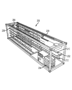
100141 Figure 2 shows a perspective view of the illustrative growing system
inside the
container shown in Figure 1.
100151 Figure 3 shows another perspective view of the illustrative growing
system inside
the container shown in Figure 1.
100161 Figure 4 shows a front devotional view of the illustrative racks
shown in Figure 3.
100171 Figure 5 shows a perspective view of the illustrative ventilation
system in the
container.
100181 Figure 6 shows an illustrative system diagram of the monitoring
system.
100191 Figure 7 shows a front devotional view of the illustrative
monitoring system.
100201 Figure 8 shows illustrative data that can be stored in the control
system in an
embodiment.
100211 Figure 9 shows an illustrative flow diagram of the process for
growing plants in an
embodiment.
100221 Figure 10 shows a perspective view of the illustrative germination
station.
100231 Figure 11 shows a front elevational view of the illustrative growing
system shown
in Figure 2.
100241 Figure 12 shows a perspective view of the illustrative irrigation
system.
100251 Figure 13 shows a perspective view of the illustrative ventilation
system shown in
Figure 5.
100261 Figure 14 shows a top level view of another embodiment of the
illustrative lighting
system.
100271 Figure 15 shows a front elevational view of the illustrative
lighting system in Figure
14.
100281 Figures 16A-16B show examples of data that can be remotely monitored
and
controlled via the illustrative monitoring system, all according to
embodiments of the present
disclosure.
100291 Figures 17A-17F show examples of additional data that can be
remotely monitored
and controlled via the illustrative monitoring system, all according to
embodiments of the
present disclosure.
100301 Figure 18 shows a schematic view of the illustrative irrigation
system according to
an embodiment of the present disclosure.
3
CA 02878003 2014-12-24
WO 2014/005156
PCT/US2013/048984
100311 Figure 19 shows a perspective view of another embodiment of the
illustrative
ventilation system.
DESCRIPTION
100321 The present disclosure is directed to a system and method for
modifying a modular
container for high-yield plant production in any environment. in one
embodiment, a
hydroponic system can expand to fit any space, and be subsequently started and
operated by an
individual with minimal training. Another embodiment allows the user to
monitor and modify
the environment and feeding conditions in order to provide optimal growth
conditions for the
specific type of plant being grown.
100331 Figure 1 shows a perspective view of the outside of illustrative
container 102
according to some embodiments of the present disclosure. In another
embodiment, container
102 can also include a water reclamation system (not shown). Container 102 can
be a recycled
shipping container with standard transnational grade intermodal perishable
food-grade
insulation foam sandwiched between the steel walls of container 102. Container
102 is also
sealed in order to create a solid modular frame for expansion, as well as a
controlled growing
environment for plants.
100341 In some embodiments, container 102 can be modified to include a
solar array 104 to
harness solar energy and store it in a converter or batteries for later use.
One of ordinary skill
in the art would recognize that other energy efficient solutions, such as
insulation paint or
planting additional crops on top of and around container 102, can also be
incorporated into
container 102 to make it even more energy efficient. Other renewable energy
technologies,
such as forms of solar and wind power, could also be added to increase
functionality. All of
these components can be relocated within the unit, outside the unit, on top of
the unit, or next
to the unit, to increase space, efficiency, and/or ease of access.
100351 Figures 2-3 show perspective views of a growing system inside the
container in
Figure 1 according to some embodiments of the disclosure. In some embodiments,
growing
system 200 can include germination station 202, climate control system 204,
LED lighting
system 206, vertical racks 304, and an irrigation system 1800. Germination
station 202
includes preparation section 210 and nutrient section 212. Referring to Figure
10, germination
station 202 is shown in more detail. Preparation section 210 is configured to
hold trays 1002
while they are loaded with a medium. 1008 that is optimal for seed
germination, such as
rockwool cubes. In other embodiments of the disclosure, medium 1008 includes
an organic
substance such as peat, pine bark, sawdust, and rice hulls. In yet other
embodiments of the
4
CA 02878003 2014-12-24
WO 2014/005156
PCT/US2013/048984
disclosure, medium 1008 includes a petroleum-based substance such as polymeric
foams or
plastic beads. In other embodiments, medium 1008 includes inorganic substances
that are
mineral-based, such as sand, gravel and perlite. One of ordinary skill in the
art would
recognize that almost any material that supports a root system, other than
soil, can be
considered a suitable material for medium 1008.
100361 Once the seeds have been placed in medium 1008, tray 1002 is placed
in nutrient
section 212 until the seeds have germinated. Figure 10 shows trays 1004 and
1006 placed in
nutrient section 212. Tray 1004 includes seeds that have germinated into
plants while tray
1006 includes seeds that have just been placed into medium 1008 and have not
yet germinated.
Nutrient section 212 provides an optimal environment for seed germination by
providing light
and water/nutrients via irrigation tubes 1010. in some embodiments,
germination station 202
utilizes the same type of irrigation system and lighting system that will be
discussed later for
plants held in vertical racks 304.
100371 Figure 4 shows a front elevatioinal view of the illustrative racks
shown in Figure 3.
Vertical racks 304 can include grow channel 402, grow medium 404, and plants
406. When
the seeds have germinated into plants 406, they are taken out of nutrient
section 212, placed
into grow channel 402 and packed in with grow medium 404. In some embodiments,
grow
medium 404 is ZIPGROWTM medium. (Bright Agrotech LLC, Laramie, Wyoming), which
is a
reusable synthetic mesh/sponge that slides into grow channel 402 as two halves
that come
together as they are pulled into grow channel 402. Grow medium 404 is
configured to hold the
root system of the plants in place.
100381 Vertical racks 304 can be placed in any configuration within
container 102 and are
configured to hold grow channels 402 in place. Grow channel 402 is removably
mounted into
vertical rack 304 so that grow channel 402 can be easily removed, replanted,
harvested and
otherwise worked on without screwing/unscrewing, clipping/unclipping or
otherwise changing
any parts. In some embodiments, grow channels 402 can be ZIPGROVv'Tm grow
channels
(Bright Agrotech LLC, Laramie, Wyoming), which utilize vertical
hydroponic/aquaponic PVC-
constructed channels. However, one of ordinary skill in the art would
recognize that other
grow channels could be used. Each grow channel 402 includes an exterior part
and an interior
part. The exterior part can hang from ceiling 302 of container 102 for
example, by using a pin.
The interior part is similarly hung from ceiling 302 of container 102, and can
be mounted on an
L-shaped bracket that is coupled to ceiling 302. The bottom of both the
interior and exterior
channels sit in a return channel (not shown) mounted on the floor of container
102. In an
CA 02878003 2014-12-24
WO 2014/005156
PCT/US2013/048984
exemplary configuration, grow channels 402 are hung vertically in racks 304,
side by side, in
four rows. hi this exemplaty configuration, two rows are on the left side and
two rows are on
the right side, with the open plant growth channels facing in toward each
other where the LED
lighting system 206 is located. The vertical configuration of racks 304 is
important as it is
more space efficient than horizontal racks. For example, in some embodiments
of the
disclosure, 12-20 plants can be placed in one vertical rack spanning from the
floor to the
ceiling, and these plants would only need five lights and a single irrigation
tube. Furthermore,
the vertical configuration of racks 304 eliminates standing water and
maintains a high flow rate
in order to prevent most problems that are currently associated with
commercial hydroponics,
such as algae growth, bacteria growth, and irrigation clogging.
100391 The combined configuration of racks 304 and plants 404 is also
important. In
embodiments of the disclosure, plants 404 are placed in vertical racks 304 so
that plants 404
grow radially outward from the axes of racks 304. This configuration provides
several
advantages over the traditional tray or shelf grow model where plants are
simply placed within
a horizontal tray or on a horizontal shelf. For example, the traditional
tray/shelf configuration
causes large areas of uncontrolled standing water. Not only is this not ideal,
but it also allows
for massive evaporation and requires additional equipment to control humidity.
The traditional
tray/shelf configuration also typically utilizes a low flow rate. However, a
low flow rate
encourages algae/bacteria growth and also requires the use of additional
equipment to aerate
the solution in order to increase its oxygen content. A low oxygen content
level would
otherwise stunt plant growth. In contrast, the configuration described in
embodiments of the
disclosure allow for a single point of standing water (nutrient reservoir
1802) that is controlled,
filtered and sterilized. By minimizing the exposed water, the configuration
can eliminate
evaporation and the need for large humidity control equipment. The
configuration allows for a
high flow rate of solution, which minimizes any algae or bacteria growth and
creates a high
level of oxygen for increased plant growth.
100401 Furthermore, in the traditional tray/shelf system, the root system
is constantly
exposed to flowing water, which can cause roots to rot while also preventing
airflow through
the root structure. The traditional tray/shelf system also has limited space
and is not flexible to
accommodate various sizes of plants, so smaller plants do not necessarily
utilize all of the
space allocated to them or might get crowded out by larger plants. In
contrast, the
configuration in embodiments of the disclosure where plants grow radially
outward from.
vertical racks forces plants to fit:tilt multiple stimuli (e.g., air, gravity,
light) to create compact,
6
CA 02878003 2014-12-24
WO 2014/005156
PCT/US2013/048984
strong stems with a robust and compact root structure. Furthermore, the
flexible plant spacing
allows for a maximum number of plants per rack, no matter how large or small
the plant.
100411 The LED lighting system 206 is configured to provide artificial
light in a controlled
manner for the growth of the plant. In the some embodiments, LED lighting
system 206 can
utilize five foot long PHILIPS (Amsterdam, Netherlands) LED light bars of Deep
Red/Blue
150 110 V grow lights. In one configuration, the light bars are mounted
horizontally in a back-
to-back configuration in two rows, one on each side in between the rows of
grow channels 402
that face each other, as shown in Figure 3. In some embodiments, each section
of the LED
light bars can be mounted with four back-to-back sets vertically and hung on
wires 208. Each
section of wire 208 can then be mounted onto rotating motor 208 on ceiling 302
to pull LED
lighting system 206 up and out of the way (like a window shade) for access to
the grow
channels 402 for removal and work. LED lighting system 206 is further
configured to be
controlled separately so that lighting in each section of the growing station
can be turned on or
off, dimmed, or lifted up or down. Figure 11 shows a front devotional view of
the illustrative
growing system shown in Figure 2. Specifically, Figure II shows the exemplary
back-to-back
sets of LED lighting system 206, hung on wires 208, in between sections of
vertical racks 304.
The configuration of LED lighting system 206 maximizes space efficiency by
using less
equipment while simultaneously maximizing the plants' exposure to lights at
the right
wavelength and spectrum. By maximizing space efficiency, growing system 200
can achieve
high plant yields while maintaining relatively low costs and a size that can
still fit a modular
shipping container. Figure 11 also shows plants 406 growing radially outward
from the grow
channels (not shown), which are being held by racks 304.
10421 In other embodiments of the disclosure, and as shown in Figures 14-
15, LED
lighting system 206 can utilize light curtain system 1400 comprising eight
foot long PHILIPS
(Amsterdam, Netherlands) Interlighting Strips 1402. Strips 1402 preferably
comprise LED
diodes inside a waterproof coating. In an embodiment of the disclosure,
conversion box 1404
is coupled to ceiling 302 of container 102, and strips 1402 are coupled to
conversion box 1404
so that they hang downward toward the floor of container 102. Strips 1402 can
be joined
together, or they can hang with predetermined spacing between each other in
order to disperse
light through plants 406. There are multiple advantages to using the
configuration of light
curtain system 1400 which cannot be utilized in other lighting systems. For
example, light
curtain system 1400 can. be used in multiple orientations and can be easily
modified for
different stages in plant growth and/or for different types of plants being
grown in a particular
7
CA 02878003 2014-12-24
WO 2014/005156
PCT/US2013/048984
space. This flexibility allows for a more efficient work and grow space, and
increases the
variety of crops that can be grown. For example, such a configuration
eliminates the need for
wires, pulleys, or bulking infrastructure that is otherwise necessary for a
lighting system. In
some embodiments of the disclosure, each strip 1402 hangs freely, can be
pushed aside like a
bead curtain, and can be easily removed and/or replaced with a simple
watertight twist-lock so
that an electrician is not needed. In some embodiments of the disclosure,
strips 1402 can be
upgraded/replaced/changed with new strips with better diodes or diodes that
that allow for
different spectrums of light based on the crop being grown. Another advantage
of light curtain
system 1400 is that conversion box 1404 allows for central conversion of AC to
DC power.
There is electrical waste each time current is converted from AC to DC, so a
single point of
conversion increases efficiency of the system. Furthermore, a single point of
conversion at
conversion box 1404 can allow for increased control of each section so that
the lights can be
turned up or down to accommodate the stage or type of growth of plants in a
particular section.
100431 in some embodiments, irrigation system 1800 is used to deliver a
water/nutrient
solution to the plants. Figure 12 shows a perspective view and Figure 18 shows
a schematic
view of the illustrative irrigation system 1800. Irrigation system 18()0 can
include nutrient
reservoir 1802, nutrient doser (not shown), first set of tubing 1202, second
set of tubing 1204,
a pump (not shown), drip emitters (not shown), and return gutters 1804. In
some embodiments,
nutrient reservoir 1802 can be a 330 gallon tank with a reverse osmosis
filter. Nutrient
reservoir 1802 can be coupled to a nutrient doser (not shown), which controls
the flow of
nutrients into nutrient reservoir 1802 in order to maintain, specific nutrient
levels prescribed by
the user.
100441 The nutrient doser (not shown) is programmable to provide different
levels and
types of nutrients depending on the type of plant being grown for optimal
growth. The nutrient
closer (not shown) can control all types of nutrients, such as, for example,
phosphates, nitrates,
trace minerals. The nutrient doser (not shown) can also be configured to
control and maintain
characteristics of the water/nutrient solution such as pH and acidity based on
prescribed levels
by the user. In some embodiments of the disclosure, the nutrient doser (not
shown) is
configured to use a simple one-part nutrient solution, while giving more
advanced users the
option to experiment with additives and trace minerals based on desired
characteristics of plant
growth and taste.
100451 Irrigation system 1800 can also include a first set and second set
of tubing 1202 and
1204 for delivery of water/nutrient solution to grow channels 402 in racks
304. First set of
8
CA 02878003 2014-12-24
WO 2014/005156
PCT/US2013/048984
tubing 1202 can be one-half inch tubing coupled to ceiling 302 of container
102, and can carry
water/nutrient solution from nutrient reservoir 1802 to each section of grow
channels 402.
Second set of tubing 1204 can be one-quarter inch tubing that carries
water/nutrient solution
from each section of grow channels 402 to each individual pow channel 402 in
rack 304. The
sizes of the tubing are exemplary only and can be modified and adjusted by one
of ordinary
skill in the art. Furthermore, one of ordinary skill in the art would
recognize that one set of
tubing, or more than two sets of tubing, could be used as well. A pump (not
shown) can be
utilized at the point of origin at nutrient reservoir 1802 to regulate the
rate of water/nutrient
flow through first set of tubing 1202. Drip emitters (not shown) may also be
affixed to the
ends of the second set of tubing 1204 to control the water/nutrient flow at
the point of release
into each grow channel 402.
100461 In some embodiments, return gutters 1804 are utilized to catch
unused
water/nutrient solution that flows through grow channel 402 and return it to
nutrient reservoir
1802. Return gutters 1804 can be coupled to the floor of the container 102 and
can be
positioned beneath and/or integrated with the terminating section of grow
channel 402. In
some embodiments, the collected unused water/nutrient solution flows downhill
through return
gutters 1804 and back into nutrient reservoir 1802. Alternatively, a
collection point/return tank
can accumulate the unused nutrient solution and utilize a pump to transport
the solution back to
the reservoir.
100471 In order to control the internal environment of container 102, the
hydroponic system
can include climate control system 204 (Fig. 2) that can measure and control
humidity, carbon
dioxide levels, temperature, and other related environmental factors.
100481 In some embodiments, the hydroponic system also can include a
ventilation system
having a main fan and a plurality of intermittent fans. Figures 5 and 13 show
perspective
views of a ventilation system according to some embodiments of the present
disclosure. The
ventilation system can include main fans 502, intermittent fans 1302, and air
vents 504.
External air is taken in by main fans 502 at one end of container 102, is
pushed through
container 102 via intermittent fans 1302, and then exhausted from container
102 at the opposite
end. Intake air is preferable run through several High Efficiency Particulate
Air (HEPA)
charcoal filters at main fans 502 and exhaust air is preferably run through
micro screen
charcoal filters. In some embodiments, ventilation system utilizes additional
air vents 504
coupled to ceiling 302 of container 102 to create a dual airflow system..
Current greenhouse
solutions, such as direct fans, indirect fans, and mass ventilation/exhaust
systems were tested,
9
CA 02878003 2014-12-24
WO 2014/005156
PCT/US2013/048984
but all were inferior to the dual airflow system in the present disclosure.
The dual airflow
system is generated from the vertical air flow from vents 504 and horizontal
air flow from main
fans 502 and intermittent fans 1302. In other embodiments of the disclosure,
additional fans
and/or vents are positioned in or on the floor of container 102 to blow air
vertically from the
ground up between rows of racks 304. Providing air flow in more than one
direction is
preferable in order to further create actual conditions that plants would
encounter outdoors.
Furthermore, the chaotic and random air flow patterns that are generated
stimulate the plants
and force them to grow stronger and denser stems and leaves. The dual airflow
system is not
possible with traditional horizontal rack systems because the racks would
block the vertical
flow of air and each rack would need its own fan/airflow source. In contrast,
in embodiments
of the disclosure, the vertical configuration of the racks along with the
added vertical flow of
air allows for air flow through the plant stems and maintains a constant flow
throughout dense
vegetation. Furthermore, the added vertical air flow, on top of the existing
horizontal air flow,
directly cools lighting while also providing an ideal level of stress to the
plants, creating
stronger cell walls in the plants. Stronger cell walls allow for a stronger
root structure, which
can support the growth of larger plants.
100491 In another embodiment of the disclosure shown in Figure 19, the
ventilation system
can also include tube 1902, which spans along the floor of container 102 in
any direction. In
one embodiment of the disclosure, tube 1902 is positioned between, and is
parallel to, gutters
1804. Tube 1902 includes end 1904, which is configured to receive a fan unit
(not shown), as
well as perforations (not shown) along the length of tube 1902. When the fan
unit (not shown)
is turned on, air is circulated along the length of tube 1902, and is released
upward through the
perforations (not shown) along tube 1902 as an alternative or additional
vertical air source.
One of ordinary skill in the art would recognize that air can flow vertically
from either the
ceiling to the floor, or from the floor to the ceiling, of container 102. One
of ordinary skill in
the art would also recognize that air flow in the horizontal and vertical
directions is just an
example and the embodiment is not limited to only two directions, nor is it
limited to those two
particular directions.
100501 In some embodiments, the components in container 102 can be coupled
to
monitoring system 600. Figure 6 shows an illustrative system diagram of
monitoring system
600 and Figure 7 shows a front elevational view of monitoring system 600.
Monitoring system
600 can include control center 602, CPU interface 604, and wireless interface
606 to allow user
608 to access the system remotely. Control center 602 preferably monitors and
controls all of
CA 02878003 2014-12-24
WO 2014/005156
PCT/US2013/048984
the components based on specifications set by user 608. For example, control
center 602 can
monitor climate control system 204 and change humidity, carbon dioxide levels,
temperature,
and other factors in. order to remain within user-specified measurements. In
another example,
control center 602 is coupled to LED lighting system 206 to control lighting
based on various
factors, such as time of day. In yet another example, control center 602 is
coupled to irrigation
system 1800 to ensure that the proper nutrient concentration for a specific
crop is being
maintained in nutrient reservoir 1802. Control center 602 can also monitor and
control the
amount of solution being dripped onto specific sections of grow channels 402,
or specific grow
channels 402 themselves. In yet another example, control center 602 can be
coupled to the
ventilation system to ensure the proper airflow is being maintained for
various sections of
plants. The above are just illustrative examples of components that can be
monitored and
controlled in order to ensure maintenance of optimal growing conditions
specified by the user.
1005n CPU interface 604 allows user 608 to have direct access to control
center 602, and
wireless interface 606 allows user 608 to have remote access to control center
602. Either
connection allows user 608 to modify any pre-set levels, override pre-set
levels, or simply
monitor activity in container 102. Wireless interface 606 allows for control
center 602 to
provide remote alerts to user 608, giving user 608 the ability to change or
override any preset
characteristics. Referring to Figure 8, an example of data 800 available to
user 608 is shown.
For example, available data 800 includes summary data 802 and input protocol
data 804.
Summary data 802 can provide user 608 with data on environmental conditions
and plant
growth. Input protocol data 804 is more flexible, and allows user 608 to input
data to change
environmental conditions or component performance.
100521 Figures 16-17 show examples of the types of data that can be
remotely monitored
and controlled via monitoring system 600. For example, Figure 16A illustrates
various vent
cycle characteristics 1601 that can be remotely set and modified with respect
to the vents in an.
embodiment of the disclosure. Figure 16B shows examples of various systems
that can be
remotely monitored and controlled. As shown in Figure 16B, when a system is
selected, an
exemplary set of icons 1602, 1604, 1606, pertaining to the selected system are
displayed. For
example, if the tank pump system is selected, an embodiment of monitoring
system 1600 might
display relationship icon 1602, cycle icon 1604, and alarm icon 1606.
Relationship icon 1602
describes the relationship that has been set up to determine what conditions
must occur for a
corresponding action to be triggered. Cycle icon 1604 allows the user to
specify the number or
frequency of cycles to run a particular system. Alarm icon 1606 allows the
user to specify the
11
CA 02878003 2014-12-24
WO 2014/005156
PCT/US2013/048984
scenarios for which monitoring system 600 should alert the user for a
particular system.
Figures 17A-F illustrate screenshots of various other types of remote
monitoring that can be
utilized by the user. Figure 17A shows a screen shot of exemplary air and
water data that can
be reported to the user. Such data can include air temperature 1702, air flow
1704, carbon
dioxide levels 1706, water temperature 1708, pH level 1710, and nutrient
conductivity 1712.
17B shows a live video feed 1714 of sweet basil plants. Monitoring system 600
can also
provide video feeds of other zones of crops being grown in container 102 in
order to allow a
user to monitor different zones of ditTerent crops or different zones of the
same crop. Figure
17C shows an example of alarm function 1716 in monitoring system 600. In this
example, the
user has configured alarm function 1716 to notitY the user when the air
temperature has
exceeded 82 degrees F or has dropped below 64 degrees F. Figure 17D
illustrates additional
systems 1718 that can be remotely monitored and controlled, Figure 17E shows
systems 1720
that can be monitored by cycles, and 17F shows an example of the controls 1722
for setting
cycles for a particular system.
100531 In another embodiment, the wireless connection in wireless interface
606 allows for
an additional party, such as off-site harvest expert or hydroponics expert
610, to communicate
with user 608 and review all of the data and conditions that are available to
user 608.
100541 One of ordinary skill in the art would recognize that the monitoring
system could
monitor, control, and change any additional components that affect the
environment or feeding
conditions. In order to maintain conditions or provide alerts, control center
602 can include
algorithms relating to environmental conditions prescribed by the user. In one
embodiment,
control center 602 utilizes a series of if-then relationships to maintain
optimal conditions. For
example, if humidity within container 102 falls below a set limit, for
example, 60%, then
control center 602 activates the humidifier until the humidity level
stabilizes. In another
example, if the temperature within container 102 rises above a set limit, for
example, 85
degrees F or falls below a set limit, for example, 66 degrees F, then control
center 602 activates
climate control system 204 until the temperature stabilizes. Monitoring system
600 can also be
configured to capture visual records of plant growth, and record and report
all data points for
conditions that the monitoring system controls. The system may also be
configured to issue
alerts based on the if-then relationships described above to alert the user of
system failures,
changes in conditions, or other variations from levels prescribed by the user.
All of these
variables can be changed based on the crop desired and the optimal
environmental and feeding
conditions for that crop.
12
CA 02878003 2014-12-24
WO 2014/005156
PCT/US2013/048984
100551 In one embodiment, assembly of the hydroponic unit starts with
obtaining a new or
used insulated shipping container 102 that in vents on each door and
preferably has
vents on each wall. In one example, there is an average of one vent per ten
feet. An electrical
panel, such as a 200 amp, 240 volt panel, can be coupled to one of the walls
of container 102
for power. A Heating, Ventilation and Air Conditioning (HVAC) unit or other
climate control
unit 204 and main fan 502 can also be coupled to one of the walls of container
102.
Intermittent fans 1302 can be installed every ten to twenty feet to allow for
proper air
circulation.
100561 Racks 304 for the growing system can then be installed within
container 102,
followed by grow channels 402. Grow channels 402 and racks 304 can be
configured
vertically in order to increase plant yield and improve usability. However,
the grow channels
402 and racks 402 can be moved, changed and/or reconfigured to increase the
efficiency of the
interior space. Once these systems are assembled, they are connected to the
nutrient reservoirs
1802, dosers (not shown), and other components of the irrigation system. The
I,ED lighting
system 206 is then set up at a proper distance from the growing system to
allow for optimum
conditions for plant production. Climate control system 204 and monitoring
system 600 can
then be installed within container 102 to ensure that all of the necessary
components are being
controlled and monitored. Cameras can also be installed and connected to the
CPU to ensure
that a live feed or time-lapse pictures can be provided to a remote user.
100571 Figure 9 shows an illustrative flow diagram of the process 900 for
growing plants in
an embodiment of the invention. In step 902, seeds are placed into germination
medium 1008
and provided with nutrients for a specified duration of time until they have
germinated into
plants. In step 904, the plants are removed from germination medium 1008. In
steps 906-908,
the plants are packed into the grow medium 404 and placed in grow channels
402. In step 910,
grow channels 402 are coupled into vertical racks 304 so that the plants grow
radially outward
from the axes of vertical racks 304. In step 912, the user programs control
center 602 with
specific environmental conditions to be monitoring and maintained. In steps
914-920, control
center 602 drives exemplary environmental factors, such as temperature,
humidity, lighting,
nutrients/water, and airflow so that they are all within levels prescribed by
the user. Once the
plants have either spent a specified duration of time in racks 304 or grown to
a specified size,
they are then removed from racks 304 and grow channels 402 in step 922.
100581 The hydroponic system can be configured to produce all plants other
than crops that
are grown for their edible roots, i.e., root crops. For example, the
hydroponic system can
13
CA 02878003 2014-12-24
WO 2014/005156
PCT/US2013/048984
produce: all types of lettuce; all types of herbs such as basil, oregano,
mint, parsley, rosemary,
thyme, and chive: all types of lea& greens such as kale, chard, spinach and
arugula; all vine
crops such as strawberries, tomatoes, and peppers; cucumbers; and mushrooms.
One of
ordinary skill in the art would recognize that these are just examples of non-
root crops, and the
disclosure is not meant to be limited to these exemplary crops only. The
hydroponic system
can also be configured to utilize fish tanks in order to raise various forms
of seafood, such as
fish, shrimp and lobsters.
100591 The disclosed system can provide a high efficiency output as plants
can be
harvested and new plants can begin the cycle all in the same space at the same
time. In one
example, the compact design of the hydroponic system provides approximately
65x output of
traditional farming in a 40x8 container that is easily implemented into
different environments.
In another example of an embodiment, one acre of the disclosed hydroponic
system provides
an annual yield of approximately 1,960,200 heads of lettuce while one acre of
traditional
agricultural farming provides an. annual yield of approximately 30,000 beads
of lettuce. In
another example, one acre of the disclosed hydroponic system provides an
annual yield of
approximately 354,925 pounds of basil while one acre of traditional
agricultural farming
provides an annual yield of approximately 32,500 pounds of basil. In yet
another example, 320
square feet of the disclosed hydroponic system provides an annual yield of
approximately
24,000 heads of lettuce while 320 square feet of traditional greenhouse
farming produces an
annual yield of approximately 6,800 heads of lettuce. Not only does the
disclosed hydroponic
system. in the previous examples provide a much higher annual yield of crops,
but it is also able
to do so with fewer resources. For example, one acre of the disclosed
hydroponic system
utilizes approximately 163,350 gallons of water annually while one acre of
traditional
agricultural farming utilizes approximately 488,772 gallons of water annually.
100601 Although the above description describes embodiments of the
invention, it should
be understood that the techniques and concepts are applicable to growing
systems in general.
Thus the invention may be embodied in other specific forms without departing
from the spirit
or essential characteristics thereof.
100611 While the above describes a particular order of operations performed
by a given
embodiment of the invention, it should be understood that such order is
exemplary, as
alternative embodiments may perform the operations in a different order,
combine certain
operations, overlap certain operations, or the like. References in the
specification to a given
embodiment indicate that the embodiment described may include a particular
feature, structure,
14
CA 02878003 2014-12-24
WO 2014/005156
PCT/US2013/048984
or characteristic, but every embodiment may not necessarily include the
particular feature,
structure, or characteristic.
1100621 While the present invention has been described in the context of a
method or
process, the present invention also relates to apparatus for performing the
operations herein.
This apparatus may be specially constructed for the required purposes, or it
may comprise a
general-purpose computer selectively activated or reconfigured by a computer
program stored
in the computer. Such a computer program may be stored in a computer readable
storage
medium including, without limitation, any type of disk including optical
disks, CD-ROMs, and
magnetic-optical disks, read-only memory (ROM), random access memory (RAM),
magnetic
or optical cards, or any type of media suitable for storing electronic
instructions.