Note: Descriptions are shown in the official language in which they were submitted.
CA 02878143 2014-12-30
WO 2014/006078
PCT/EP2013/064006
- 1 -
COMBUSTIBLE HEAT SOURCE WITH IMPROVED BINDING AGENT
The present invention relates to a combustible heat source for a smoking
article, the
heat source comprising carbon and an improved binding agent including a
combination of
organic and inorganic binder materials. The invention further relates to a
heated smoking article
comprising such a combustible heat source and an aerosol-forming substrate.
A number of smoking articles in which tobacco is heated rather than combusted
have
been proposed in the art. One aim of such 'heated' smoking articles is to
reduce known harmful
smoke constituents of the type produced by the combustion and pyrolytic
degradation of
tobacco in conventional cigarettes.
In one known type of heated smoking article, an aerosol is generated by the
transfer of
heat from a combustible heat source to an aerosol-forming substrate located
downstream of the
combustible heat source. During smoking, volatile compounds are released from
the aerosol-
forming substrate by heat transfer from the combustible heat source and
entrained in air drawn
through the smoking article. As the released compounds cool, they condense to
form an
aerosol that is inhaled by the user.
For example, WO-A-2009/022232 discloses a smoking article comprising a
combustible
heat source, an aerosol-forming substrate downstream of the combustible heat
source, and a
heat-conducting element around and in contact with a rear portion of the
combustible heat
source and an adjacent front portion of the aerosol-forming substrate. The
heat-conducting
element in the smoking article of WO-A-2009/022232 helps transfer the heat
generated during
combustion of the heat source to the aerosol-forming substrate.
Some carbon-based heat sources incorporate an organic binder, such as a
cellulose
derivative, to help improve integrity of the heat source during manufacture,
processing and
storage. However, organic binders are typically combustible at the
temperatures reached within
the heat source during burning. As a result, the organic binders have been
found to disintegrate
during smoking of the heated smoking article, leading to a loss of integrity
of the heat source.
The disintegration of the organic binder may result in deformation of the heat
source
during and after burning, which may in turn cause cracking or breakage of the
heat source or
the release of ash from the combusted heat source. Furthermore, during burning
of the organic
binder, gases are typically released which create pressure within the heat
source, further
increasing the likelihood of cracking or breakage.
It would be desirable to provide a combustible heat source for a heated
smoking article,
which has improved integrity during and after smoking. It would be
particularly desirable to
provide such a combustible heat source which also has improved burning
properties.
According to the invention there is provided a combustible heat source for a
smoking
article, the combustible heat source comprising carbon and a binding agent
including at least
CA 02878143 2014-12-30
WO 2014/006078
PCT/EP2013/064006
- 2 -
one organic polymeric binder material, at least one carboxylate burn salt and
at least one non-
combustible, inorganic binder material, wherein the at least one non-
combustible inorganic
binder material comprises a sheet silicate material.
According to the invention there is also provided a smoking article comprising
a
combustible heat source according to the invention, as defined above, and an
aerosol-forming
substrate downstream of the combustible heat source.
The invention further provides the use of a binding agent to improve the
integrity of a
carbon-containing combustible heat source for a smoking article, the binding
agent comprising
at least one organic polymeric binder material, at least one carboxylate burn
salt and at least
one non-combustible inorganic binder material, wherein the at least one non-
combustible
inorganic binder material comprises a sheet silicate material.
The invention further provides a method of producing a combustible heat source
having
improved integrity, the method comprising the steps of: combining one or more
carbon-
containing materials with a binding agent including at least one organic
polymeric binder
material, at least one carboxylate burn salt and at least one non-combustible
inorganic binder
material, wherein the at least one non-combustible inorganic binder material
comprises a sheet
silicate material; pre-forming the mixture of the one or more carbon-
containing materials and the
binding agent into an elongate rod; and drying the elongate rod.
The combustible heat source of the invention may be an extruded heat source,
formed
by an extrusion process, as described in more detail below. Alternatively and
preferably, the
combustible heat source of the invention may be a pressed heat source, formed
by a pressing
process, as also described in more detail below. Pressed heat sources have
been found to
show the most improvement in integrity as a result of the use of a binding
agent including the
combination of three components defined above.
The term "binding agent" is used herein to refer to the component of the
combustible
heat source that binds the carbon and any other additives within the heat
source together, such
that a solid heat source can be formed that retains its structure.
The term "carboxylate burn salt" is used herein to refer to a salt of a
carboxylic acid,
which is believed to modify carbon combustion. Preferably, the carboxylate
burn salt comprises
a monovalent, divalent, or trivalent cation and a carboxylate anion at room
temperature, wherein
the carboxylate anion burns when the combustible heat source is lit. More
preferably, the
carboxylate burn salt is an alkali metal carboxylate burn salt comprising a
monovalent alkali
metal cation and a carboxylate anion at room temperature, wherein the
carboxylate anion burns
when the combustible heat source is lit. Specific examples of carboxylate burn
salts that may
be included in the binding agent of the combustible heat source of the
invention include, but are
not limited to, alkali metal acetates, alkali metal citrates and alkali metal
succinates.
CA 02878143 2014-12-30
WO 2014/006078
PCT/EP2013/064006
- 3 -
In certain embodiments, the binding agent may include a single carboxylate
burn salt. In
other embodiments, the binding agent may comprise a combination of two or more
different
carboxylate burn salts. The two or more different carboxylate burn salts may
comprise different
carboxylate anions. Alternatively or in addition, the two or more different
carboxylate burn salts
may comprise different cations. By way of example, the binding agent may
comprise a mixture
of an alkali metal citrate and an alkaline earth metal succinate.
The term "non-combustible" is used herein to refer to an inorganic binder
material that
does not burn or decompose during ignition and burning of the combustible heat
source of the
invention.
The non-combustible inorganic binder material is therefore stable at the
temperatures to which the binding agent is subjected during burning of the
combustible heat
source and will remain substantially intact during and after burning.
The terms "upstream", "front", "downstream" and "rear" are used herein to
describe the
relative positions of components or portions of components of smoking articles
of the invention
in relation to the direction of air drawn through the smoking articles during
use.
In the combustible heat source of the invention, carbon is combined with a
binding agent
formed of a specific novel combination of organic and inorganic binder
materials. In particular,
an organic polymeric binder material, such as those used in the combustible
heat sources of the
prior art, is combined with at least one carboxylate burn salt and at least
one non-combustible
inorganic binder material wherein the at least one non-combustible inorganic
binder material
comprises a sheet silicate material. In the following description, the organic
polymeric binder
material, the carboxylate burn salt and the non-combustible inorganic binder
material are
referred to collectively as the "binder components".
The use of a binding agent including a specific combination of an organic
polymeric
binder material, a carboxylate burn salt and a non-combustible inorganic
binder material
comprising a sheet silicate material has advantageously been found to increase
the integrity of
the combustible heat source during and after burning, compared to a heat
source comprising
only organic binder material. The combustible heat source of the invention
exhibits reduced
deformation due to burning so that the occurrence of cracks, breakage or
fragmentation of the
heat source is reduced. Furthermore, the combustible heat source of the
invention forms a
more cohesive ash after burning, so that particles or fragments of the ash are
less likely to
break away from the heat source. The appearance of the ash is also found to be
improved, with
a more uniform consistency and a darker and more uniform colour.
The term "integrity" is used herein to refer to the ability of the combustible
heat source of
the invention to remain whole or intact. Any significant loss of integrity of
the combustible heat
source can result in cracking or breakage of the heat source. Poor integrity
of a combustible
heat source may also be indicated by the generation of sparks or flames during
lighting of the
heat source.
CA 02878143 2014-12-30
WO 2014/006078
PCT/EP2013/064006
- 4 -
As described in more detail below, a quantitative measure of the integrity of
a
combustible heat source can be provided using an experimental test in which
the likelihood of a
part of the combustible heat source within a heated smoking article dropping
off under
controlled burn conditions, known as "drop off", is measured. In particular,
the test provides for
a direct comparison of the integrity of combustible heat sources including
different binding
agents. It has been found that the likelihood of drop off for a combustible
heat source of the
invention is reduced compared to the likelihood of drop off under the same
conditions for a
combustible heat source of the prior art including only organic binder
material.
The lower the likelihood of drop off for a combustible heat source, the better
the integrity
of the combustible heat source is considered to be. Preferably, the likelihood
of drop off for a
combustible heat source of the invention is less than 20 percent, more
preferably less than
10 percent and most preferably close to 0 percent under the experimental
conditions described
below.
The improvement provided in the integrity of the combustible heat source as a
result of
the use of the specific combination of binder components defined above is
greater than could
be predicted based on the behaviour of the individual binder components. In
addition, the use
of the combination of the three binder components has been shown to provide an
unexpected
improvement in the mechanical strength of the combustible heat source, as
demonstrated by an
increase in the compressive strength of the combustible heat source. The
binding agent
therefore provides surprising, advantageous effects on the physical properties
of the
combustible heat source of the invention.
It has also advantageously been found that the ratio of the three binder
components of
the binding agent of the combustible heat source of the invention can be
adjusted in order to
modify and improve the burning properties of the heat source. For example, the
ratio of the
binder components may be adapted to increase the burn temperature or the burn
lifetime of the
heat source compared to a heat source including only organic binder material.
The use of a binding agent comprising the combination of three different
binder
components in the combustible heat source of the invention has also
advantageously been
shown to increase the speed of propagation of combustion of the carbon of the
heat source
from the front end to the rear end of the heat source after ignition of the
front end thereof. The
propagation of the combustion of the carbon through the combustible heat
source is clearly
shown by a change in colour at the surface of the combustible heat source due
to downstream
movement of a deflagration front from the front end to the rear end of the
combustible heat
source. The faster propagation of the combustion of the carbon through the
combustible heat
source after ignition advantageously reduces the time to first puff. As
described in more detail
below, the three different binder components of the binding agent each provide
a different
structure and function within the combustible heat source. Furthermore, the
binder components
CA 02878143 2014-12-30
WO 2014/006078
PCT/EP2013/064006
- 5 -
each behave differently upon burning of the combustible heat source. The
combination of the
different properties and behaviours of the binder components provides improved
binding effects
and in particular the surprising improvement in the integrity of the
combustible heat source.
The organic polymeric binder in the binding agent of the combustible heat
source of the
invention is typically formed of long and flexible organic polymers. The
organic polymeric binder
material is typically a good fuel which improves the burning qualities of the
combustible heat
source. As set out above, the organic polymeric binder material also helps
bind the carbon
during production of the combustible heat source and prior to burning.
However, the organic
polymeric binder material burns away after ignition of the heat source and so
does not provide
any significant binding effect during or after burning.
The organic polymeric binder material may include any suitable organic
polymeric
binders that do not produce harmful by-products upon heating or burning. The
organic
polymeric binder material may include a single type of organic polymer or a
combination of two
of more different types of organic polymer. Preferably, the organic polymeric
binder material
comprises one or more cellulosic polymer materials. Suitable cellulosic
polymer materials
include but are not limited to cellulose, modified cellulose, methyl
cellulose, carboxymethyl
cellulose, hydroxypropyl cellulose, hydroxypropyl methylcellulose and
combinations thereof. In
particularly preferred embodiments of the invention, the organic polymeric
binder material
comprises carboxymethyl cellulose (CMC). A suitable source of CMC for use in
the invention is
available from Phrikolat GmbH, Germany. Alternatively or in addition to the
one or more
cellulosic polymer materials, the organic polymeric binder material may
comprise one or more
non-cellulosic polymer materials, including but not limited to gums, such as
for example guar
gum; wheat flour; starches; sugars; vegetable oils and combinations thereof.
Preferably, the binding agent includes between about 25 percent by weight and
about
80 percent by weight of the organic polymeric binder material, more preferably
between about
percent by weight and about 75 percent by weight of the organic polymeric
binder material.
In contrast to the organic polymeric binder material, the carboxylate burn
salt in the
binding agent of the combustible heat source of the invention typically
comprises ions that are
generally smaller in size to the other, larger molecules in the heat source.
The carboxylate burn
30 salt promotes the combustion of the heat source. In addition, unlike the
organic binder, the
carboxylate burn salt has been found to retain a cohesive structure around the
other molecules
within the combustible heat source during and after burning, which helps to
bind the heat source
materials together. The carboxylate burn salt therefore improves the
integrity of the
combustible heat source during and after burning and reduces the likelihood of
deformation and
breakage of the heat source. The retention of the binding effect of the
carboxylate burn salt
after burning additionally improves the cohesion and appearance of the ash
material.
CA 02878143 2014-12-30
WO 2014/006078
PCT/EP2013/064006
- 6 -
The inclusion of a carboxylate burn salt in the combustible heat source of the
invention
additionally provides improvement in the burning properties of the combustible
heat source. In
particular, the carboxylate burn salt may increase the burning time of the
combustible heat
source of the invention compared to combustible heat sources including only
organic binder
material. Furthermore, the promotion of combustion of the heat source by the
carboxylate burn
salt may enable a combustible heat source of a higher density to be used in a
heated smoking
article. This enables a combustible heat source to be produced with a higher
quantity of the
carbon fuel for a heat source of a given size, which can further improve the
burning time of the
combustible heat source.
Preferably, the carboxylate burn salt is a potassium or sodium salt of a
carboxylic acid
such as a citrate, acetate or succinate. In preferred embodiments, the
carboxylate burn salt is
an alkali metal citrate salt.
In particularly preferred embodiments of the invention, the
carboxylate burn salt is potassium citrate, most preferably mono-potassium
citrate.
The nature of the cation and the nature of the anion selected for the
carboxylate burn
salt may both have an impact on the burning properties of the combustible heat
source and in
particular, on the burning lifetime, the burning temperature and the initial
temperature during
ignition of the combustible heat source. The nature of the carboxylate burn
salt and the amount
of carboxylate burn salt incorporated into the binding agent can therefore be
adjusted
depending on the desired burning properties of the combustible heat source.
Preferably, the binding agent comprises between about 5 percent by weight and
about
50 percent by weight of the carboxylate burn salt, more preferably between
about 8 percent by
weight and about 40 percent by weight of the carboxylate burn salt.
The non-combustible inorganic binder material comprises a sheet silicate
material.
The inorganic binder material is preferably formed of a material with
relatively large, flat
and inflexible molecules. The inorganic binder material is non-combustible at
the temperatures
reached within the combustible heat source during burning, so that the
inorganic binder is still
present after ignition and burning of the heat source. The inorganic binder
material therefore
retains its binding properties and will continue to bind together the heat
source materials after
the organic binder has been burnt away. At certain levels, the addition of an
inorganic binder
material may additionally increase the burning temperature of the combustible
heat source so
that the burning properties can be adjusted. In particular, the level of the
non-combustible
inorganic binder material may be adjusted to increase the temperature of the
heat source during
ignition.
The inorganic binder material may include any suitable inorganic binders that
are inert
and do not burn or decompose during combustion of the heat source. The non-
combustible
inorganic binder material may include a single type of inorganic binder or a
combination of two
of more different types of inorganic binder. Suitable sheet silicate materials
for inclusion in the
CA 02878143 2014-12-30
WO 2014/006078
PCT/EP2013/064006
- 7 -
non-combustible inorganic binder material include but are not limited to
clays, micas,
serpentinites and combinations thereof. In particularly preferred
embodiments, the non-
combustible inorganic binder material comprises one or more clays. Other
suitable inorganic
binders for inclusion in the non-combustible inorganic binder material include
but are not limited
to alumina-silicate derivatives, alkali silicates, limestone derivatives,
alkaline earth compounds
and derivatives, aluminium compounds and derivatives, and combinations
thereof.
The term "clay" is used herein to refer to aluminium phyllosilicate materials
formed of two
dimensional sheets of silicate and aluminate ions, which form a distinct
layered structure within
the clay. Suitable clays for use in the in the binding agent of the
combustible heat source of the
invention include, but are not limited to, bentonite, montmorillonite and
kaolinite. Suitable clays
are available from Worlee-Chimie GmbH, Germany or Nanocor.
Particularly preferably, the one or more clays used in the binding agent of
the
combustible heat source of the invention are exfoliated clays. The term
"exfoliated clays" is
used herein to refer to clays which have undergone an exfoliation or
delamination process, in
which the separation between the layers of silicate and aluminate sheets is
increased, in some
cases by up to 20 times or more.
The large, flat structure of sheet silicate materials such as clays is in
contrast to the long,
flexible molecules of the organic binder material and the small ions of the
carboxylate burn salt.
The combination of the binder molecules with these different structures has
been found to be
effective in providing improved binding properties, not only during production
and storage of the
combustible heat source of the invention, but also during and after burning.
Preferably, the binding agent comprises between about 10 percent by weight and
about
35 percent by weight of the non-combustible inorganic binder material, more
preferably between
about 15 percent by weight and about 35 percent by weight of the non-
combustible inorganic
binder material.
In particularly preferred embodiments of the invention, the combustible heat
source
comprises a binding agent comprising a combination of carboxymethyl cellulose
as the organic
binder material, potassium citrate as the carboxylate burn salt and clay as
the non-combustible
inorganic binder material. In certain preferred embodiments, the binding agent
comprises about
73 percent by weight of carboxymethyl cellulose as the organic binder
material, about
17 percent by weight of potassium citrate as the carboxylate burn salt and
about 10 percent by
weight of clay as the non-combustible inorganic binder material
This combination of binder components has been found to show particularly
effective
binding properties and the resultant combustible heat sources retain
integrity, with little or no
visible deformation or cracking during or after burning. The ash that remains
after combustion
of the combustible heat source including this combination of binder components
has also been
CA 02878143 2014-12-30
WO 2014/006078
PCT/EP2013/064006
- 8 -
found to have an improved cohesion and appearance compared to combustible heat
sources of
the prior art including only organic binder material.
Combustible heat sources of the invention preferably comprise between about 2
percent
by weight and about 10 percent by weight of the binding agent including the
three different
binder components, more preferably between about 4 percent by weight and about
10 percent
by weight of the binding agent and most preferably between about 5 percent by
weight and
about 9 percent by weight of the binding agent. In certain preferred
embodiments, combustible
heat sources of the invention comprise about 8 percent by weight of the
binding agent
The binding agent is preferably incorporated into the combustible heat source
of the
invention during production of the heat source. A combination of the three
binder components
of the binding agent may be incorporated into the heat source material in a
single step during
production or the three binder components may be added in two or three
separate steps.
One or more binder components of the binding agent may be added to the other
components of the combustible heat source in the form of a solid,
substantially dry powder.
Alternatively, one or more of the binder components of the binding agent may
be added to the
other components of the combustible heat source in the form of a binder
solution comprising the
one or more binder components dissolved or suspended in a suitable solvent,
such as water.
Preferably, at least the carboxylate burn salt is added to the other
components of the
combustible heat source in the form of a solution. For example, where the
carboxylate burn salt
comprises potassium citrate, a solution of between 5 wt% and 10 wt% of
potassium citrate in
water may be used.
Where one or more of the binder components of the binding agent are
incorporated in
the form of a binder solution, the pH of the binder solution is preferably
adapted to a basic pH of
at least pH 8, more preferably at least pH 10 and most preferably about pH 12.
The natural pH
of the solution will typically be acidic and in such cases the pH can readily
be increased through
the addition of a suitable alkali.
The binder components and in particular the organic polymeric binder material
are
typically sensitive to changes in pH. This may be particularly true for a
charged organic
polymeric binder material, for which an increase in the pH of the binder
solution may influence
the charge on the binder molecules and therefore the molecular configuration
and the binding
properties. It has been found that the use of a binder solution having a basic
pH (pH 8 or
above) improves the burning properties of the combustible heat source of the
invention
compared to a similar combustible heat source formed using an acidic binder
solution. In
particular, it has been found that the combustible heat source has an
increased burn lifetime so
that the combustible heat source can continue burning for a longer time.
Furthermore, the use of a basic binder solution has been found to produce a
combustible heat source of increased density and to improve the integrity of
the combustible
CA 02878143 2014-12-30
WO 2014/006078
PCT/EP2013/064006
- 9 -
heat source after burning compared to a similar combustible heat source formed
using an acidic
binder solution.
Combustible heat sources of the invention are carbon-containing heat source
comprising
carbon as a fuel. Preferably, combustible heat sources according to the
invention have a
carbon content of at least about 35 percent, more preferably of at least about
40 percent, most
preferably of at least about 45 percent by dry weight of the combustible heat
source.
In some embodiments, the combustible heat source according to the invention is
a
carbon-based heat source. As used herein, the term "carbon-based heat source"
is used to
describe a heat source comprised primarily of carbon. Combustible carbon-based
heat sources
for use in smoking articles according to the invention may have a carbon
content of at least
about 50 percent, preferably of at least about 60 percent, more preferably of
at least about
70 percent, most preferably of at least about 80 percent by dry weight of the
combustible
carbon-based heat source.
Combustible heat sources according to the invention may be formed from one or
more
suitable carbon-containing materials. Suitable carbon-containing materials are
well known in
the art and include, but are not limited to, carbon powder.
Combustible heat sources according to the invention preferably further
comprise at least
one ignition aid.
As used herein, the term "ignition aid" denotes a material that releases one
or both of
energy and oxygen during ignition of the combustible heat source, where the
rate of release of
one or both of energy and oxygen by the material is not ambient oxygen
diffusion limited. In
other words, the rate of release of one or both of energy and oxygen by the
material during
ignition of the combustible heat source is largely independent of the rate at
which ambient
oxygen can reach the material. As used herein, the term "ignition aid" also
denotes an
elemental metal that releases energy during ignition of the combustible heat
source, wherein
the ignition temperature of the elemental metal is below about 500 C and the
heat of
combustion of the elemental metal is at least about 5 kJ/g.
As used herein, the term "ignition aid" does not include carboxylate burn
salts, as
defined above.
Suitable ignition aids for use in the combustible heat source of the invention
are known
in the art.
Combustible heat sources according to the invention may comprise one or more
ignition
aids consisting of a single element or compound that release energy upon
ignition of the
combustible heat source. The release of energy by the one or more ignition
aids upon ignition
of the combustible heat source directly causes a 'boost' in temperature during
an initial stage of
combustion of the combustible heat source.
CA 02878143 2014-12-30
WO 2014/006078
PCT/EP2013/064006
- 1 0 -
For example, in certain embodiments combustible heat sources according to the
invention may comprise one or more energetic materials consisting of a single
element or
compound that reacts exothermically with oxygen upon ignition of the
combustible heat sources.
Examples of suitable energetic materials include, but are not limited to,
aluminium, iron,
magnesium and zirconium.
Alternatively or in addition, combustible heat sources according to the
invention may
comprise one or more ignition aids comprising two or more elements or
compounds that react
with one another to release energy upon ignition of the combustible heat
source.
For example, in certain embodiments combustible heat sources according to the
invention may comprise one or more thermites or thermite composites comprising
a reducing
agent such as, for example, a metal, and an oxidizing agent such as, for
example, a metal
oxide, that react with one another to release energy upon ignition of the
combustible heat
sources. Examples of suitable metals include, but are not limited to,
magnesium, and examples
of suitable metal oxides include, but are not limited to, iron oxide (Fe203)
and aluminium oxide
(A1203)
In other embodiments, combustible heat sources according to the invention may
comprise one or more ignition aids comprising other materials that undergo
exothermic
reactions upon ignition of the combustible heat source. Examples of suitable
metals include,
but are not limited to, intermetallic and bi-metallic materials, metal
carbides and metal hydrides.
In preferred embodiments, combustible heat sources according to the invention
comprise at least one ignition aid that releases oxygen during ignition of the
combustible heat
source.
In such embodiments, the release of oxygen by the at least one ignition aid
upon ignition
of the combustible heat source indirectly results in a 'boost' in temperature
during an initial
stage of combustion of the combustible heat source by increasing the rate of
combustion of the
combustible heat source.
For example, combustible heat sources according to the invention may comprise
one or
more oxidizing agents that decompose to release oxygen upon ignition of the
combustible heat
source. Combustible heat sources according to the invention may comprise
organic oxidizing
agents, inorganic oxidizing agents or a combination thereof. Examples of
suitable oxidizing
agents include, but are not limited to: nitrates such as, for example,
potassium nitrate, calcium
nitrate, strontium nitrate, sodium nitrate, barium nitrate, lithium nitrate,
aluminium nitrate and
iron nitrate; nitrites; other organic and inorganic nitro compounds; chlorates
such as, for
example, sodium chlorate and potassium chlorate; perchlorates such as, for
example, sodium
perchlorate; chlorites; bromates such as, for example, sodium bromate and
potassium bromate;
perbromates; bromites; borates such as, for example, sodium borate and
potassium borate;
ferrates such as, for example, barium ferrate; ferrites; manganates such as,
for example,
CA 02878143 2014-12-30
WO 2014/006078
PCT/EP2013/064006
- 11 -
potassium manganate; permanganates such as, for example, potassium
permanganate;
organic peroxides such as, for example, benzoyl peroxide and acetone peroxide;
inorganic
peroxides such as, for example, hydrogen peroxide, strontium peroxide,
magnesium peroxide,
calcium peroxide, barium peroxide, zinc peroxide and lithium peroxide;
superoxides such as, for
example, potassium superoxide and sodium superoxide; iodates; periodates;
iodites; sulphates;
sulfites; other sulfoxides; phosphates; phosphinates; phosphites; and
phosphanites.
Alternatively or in addition, combustible heat sources according to the
invention may
comprise one or more oxygen storage or sequestering materials that release
oxygen upon
ignition of the combustible heat source. Combustible heat sources according to
the invention
may comprise oxygen storage or sequestering materials that store and release
oxygen by
means of encapsulation, physisorption, chemisorption, structural change or a
combination
thereof. Examples of suitable oxygen storage or sequestering materials
include, but are not
limited to: metal surfaces such as, for example, metallic silver or metallic
gold surfaces; mixed
metal oxides; molecular sieves; zeolites; metal-organic frameworks; covalent
organic
frameworks; spinels; and perovskites.
Combustible heat sources according to the invention may comprise one or more
ignition
aids consisting of a single element or compound that release oxygen upon
ignition of the
combustible heat source. Alternatively or in addition, combustible heat
sources according to the
invention may comprise one or more ignition aids comprising two or more
elements or
compounds that react with one another to release oxygen upon ignition of the
combustible heat
source.
Combustible heat sources according to the invention may comprise one or more
ignition
aids that release both energy and oxygen upon ignition of the combustible heat
source. For
example, combustible heat sources according to the invention may comprise one
or more
oxidizing agents that decompose exothermically to release oxygen upon ignition
of the
combustible heat source.
Alternatively, or in addition, combustible heat sources according to the
invention may
comprise one or more first ignition aids that release energy upon ignition of
the combustible
heat source and one or more second ignition aids, which are different from the
one or more first
ignition aids and that release oxygen upon ignition of the combustible heat
source.
In certain embodiments, combustible heat sources according to the invention
may
comprise at least one metal nitrate salt having a thermal decomposition
temperature of less
than about 600 C, more preferably of less than about 400 C.
Preferably, the at least one metal nitrate salt has a decomposition
temperature of
between about 150 C and about 600 C, more preferably of between about 200 C
and about
400 C.
CA 02878143 2014-12-30
WO 2014/006078
PCT/EP2013/064006
- 12 -
In such embodiments, when the combustible heat source is exposed to a
conventional
yellow flame lighter or other ignition means, the at least one metal nitrate
salt decomposes to
release oxygen and energy. This causes an initial boost in the temperature of
the combustible
heat source and also aids in the ignition of the combustible heat source.
Following
decomposition of the at least one metal nitrate salt, the combustible heat
source continues to
combust at a lower temperature.
The inclusion of at least one metal nitrate salt advantageously results in
ignition of the
combustible heat source being initiated internally, and not only at a point on
the surface thereof.
In certain embodimentsõ the at least one metal nitrate salt is distributed
substantially
homogeneously throughout the combustible heat source.
Preferably, the at least one metal nitrate salt is present in the combustible
heat source in
an amount of between about 20 percent and about 50 percent by dry weight of
the combustible
heat source.
Preferably, the at least one metal nitrate salt is selected from the group
consisting of
potassium nitrate, sodium nitrate, calcium nitrate, strontium nitrate, barium
nitrate, lithium
nitrate, aluminium nitrate and iron nitrate.
In certain embodiments, combustible heat sources according to the invention
may
comprise at least two different metal nitrate salts.
In one embodiment, combustible heat sources according to the invention
comprise
potassium nitrate, calcium nitrate and strontium nitrate. Preferably, the
potassium nitrate is
present in an amount of between about 5 percent and about 15 percent by dry
weight of the
combustible heat sources the calcium nitrate is present in an amount of
between about
2 percent and about 10 percent by dry weight of the combustible heat source
and the strontium
nitrate is present in an amount of between about 15 percent by weight and
about 25 percent by
dry weight of the combustible heat source.
In other embodiments, combustible heat sources according to the invention may
comprise at least one peroxide or superoxide that actively evolves oxygen at a
temperature of
less than about 600 C, more preferably at a temperature of less than about 400
C.
Preferably, the at least one peroxide or superoxide actively evolves oxygen at
a
temperature of between about 150 C and about 600 C, more preferably of between
about
200 C and about 400 C, most preferably at a temperature of about 350 C.
In use, when the combustible heat source is exposed to a yellow flame lighter
or other
ignition means, the at least one peroxide or superoxide decomposes to release
oxygen. This
causes an initial boost in the temperature of the combustible heat sources and
also aids in the
ignition of the combustible heat sources. Following decomposition of the at
least one peroxide
or superoxide, the combustible heat source continues to combust at a lower
temperature.
Preferably, the at least one peroxide or superoxide is present in the
combustible heat
CA 02878143 2014-12-30
WO 2014/006078
PCT/EP2013/064006
- 13 -
sources in an amount of between about 20 percent and about 50 percent by dry
weight of the
combustible heat sources, more preferably in an amount of between about 30
percent and
about 50 percent by dry weight of the combustible heat source.
Suitable peroxides and superoxides for inclusion in combustible heat sources
according
to the invention include, but are not limited to, calcium peroxide, strontium
peroxide, magnesium
peroxide, barium peroxide, lithium peroxide, zinc peroxide, potassium
superoxide and sodium
superoxide.
Preferably, the at least one peroxide is selected from the group consisting of
calcium
peroxide, strontium peroxide, magnesium peroxide, barium peroxide and
combinations thereof.
Alternatively or in addition to the at least one ignition aid, combustible
heat sources
according to the invention may comprise one or more other additives to improve
the properties
of the combustible heat sources. Suitable additives include, but are not
limited to, additives to
promote consolidation of the combustible heat source (for example, sintering
aids) and additives
to promote decomposition of one or more gases produced by combustion of the
combustible
heat source (for example catalysts, such as CuO, Fe203 and A1203).
Combustible heat sources according to the invention are preferably formed by
mixing
one or more carbon-containing materials with the binding agent and other
additives, where
included, and pre-forming the mixture into a desired shape. The mixture of one
or more carbon
containing materials, binding agent and optional other additives may be pre-
formed into a
desired shape using any suitable known ceramic forming methods such as, for
example, slip
casting, extrusion, injection moulding, die compaction or pressing.
In certain preferred
embodiments, the mixture is pre-formed into a desired shape by extrusion or
pressing.
Preferably, the mixture of one or more carbon-containing materials, binding
agent and
other additives is pre-formed into an elongate rod. However, it will be
appreciated that the
mixture of one or more carbon-containing materials, binding agent and other
additives may be
pre-formed into other desired shapes.
After formation, particularly after extrusion, the elongate rod or other
desired shape is
preferably dried to reduce its moisture content and then pyrolysed in a non-
oxidizing
atmosphere at a temperature sufficient to carbonise the binding agent and
substantially
eliminate any volatiles in the elongate rod or other shape. The elongate rod
or other desired
shape is pyrolysed, preferably in a nitrogen atmosphere at a temperature of
between about
700 C and about 900 C.
The combustible heat source preferably has a porosity of between about 20
percent and
about 80 percent, more preferably of between about 20 percent and 60 percent.
Even more
preferably, the combustible heat source has a porosity of between about 50
percent and about
70 percent, more preferably of between about 50 percent and about 60 percent
as measured
by, for example, mercury porosimetry or helium pycnometry. The required
porosity may be
CA 02878143 2014-12-30
WO 2014/006078
PCT/EP2013/064006
- 14 -
readily achieved during production of the combustible heat source using
conventional methods
and technology.
Advantageously, combustible heat sources according to the invention have an
apparent
density of between about 0.6 g/cm3 and about 1.0 g/cm3.
Preferably, combustible heat sources according to the invention have a mass of
between
about 300 mg and about 500 mg, more preferably of between about 400 mg and
about 450 mg.
Preferably, combustible heat sources according to the invention have a length
of
between about 5 mm and about 20 mm, more preferably of between about 7 mm and
about 15
mm, most preferably of between about 11 mm and about 13 mm. As used herein,
the term
"length" denotes the maximum longitudinal dimension of elongate combustible
heat sources
according to the invention between the upstream end and the downstream end
thereof.
Preferably, combustible heat sources according to the invention have a
diameter of
between about 5 mm and about 10 mm, more preferably of between about 7 mm and
about
8 mm. As used herein, the term "diameter" denotes the maximum transverse
dimension of
elongate combustible heat sources according to the invention.
Preferably, combustible heat sources according to the invention are of
substantially
uniform diameter. However, combustible heat sources according to the invention
may
alternatively be tapered so that the diameter of the rear portion of the
combustible heat source
is greater than the diameter of the front portion thereof. Particularly
preferred are combustible
heat sources that are substantially cylindrical. The combustible heat source
may, for example,
be a cylinder or tapered cylinder of substantially circular cross-section or a
cylinder or tapered
cylinder of substantially elliptical cross-section.
Combustible heat sources according to the invention may be "blind" combustible
heat
sources. As used herein, the term "blind combustible heat source" is used to
denote a
combustible heat source that does not contain any longitudinal airflow
channels. As used
herein, the term "longitudinal airflow channel" is used to denote a hole
passing through an inner
portion of the combustible heat source and extending along the entire length
of the combustible
heat source.
Alternatively, combustible heat sources according to the invention may
comprise at least
one longitudinal airflow channel. For example, combustible heat sources
according to the
invention may comprise one, two or three longitudinal airflow channels. In
such embodiments,
combustible heat sources according to the invention preferably comprise a
single longitudinal
airflow channel, more preferably a single substantially central longitudinal
airflow channel. The
diameter of the single longitudinal airflow channel is preferably between
about 1.5 mm and
about 3 mm.
The inner surface of the at least one longitudinal airflow channel of
combustible heat
sources according to the invention may be partially or entirely coated.
Preferably, the coating
CA 02878143 2014-12-30
WO 2014/006078
PCT/EP2013/064006
- 15 -
covers the inner surface of all longitudinal airflow channels.
Optionally, combustible heat sources according to the invention may comprise
one or
more, preferably up to and including six, longitudinal grooves that extend
along part of or the
entire periphery of the combustible heat sources. If desired, combustible heat
sources
according to the invention may comprise one or more longitudinal grooves and
at least one
longitudinal airflow channel. Alternatively, combustible heat sources
according to the invention
may be blind combustible heat sources comprising one or more longitudinal
grooves.
Preferably, at least a part of the combustible heat sources according to the
invention is
wrapped in a combustion resistant wrapper. The term "combustion resistant" is
used herein to
refer to a wrapper that remains substantially intact throughout combustion of
the combustible
heat source. The combustion resistant wrapper is preferably wrapped around and
in direct
contact with at least a part of the combustible heat source. Preferably, at
least a rear or
downstream part of the combustible heat source is wrapped in the combustion
resistant
wrapper. Preferably, at least a front or upstream part of the combustible heat
source is not
wrapped in the combustion resistant wrapper.
Combustible heat sources according to the invention may be wrapped in a
combustion
resistant wrapper that is heat-conducting.
In use in smoking articles according to the invention, heat generated during
combustion
of combustible heat sources according to the invention wrapped in a heat-
conducting
combustion resistant wrapper may be transferred by conduction to the aerosol-
forming
substrate of the smoking articles via the heat-conducting combustion resistant
wrapper.
Alternatively or in addition, combustible heat sources according to the
invention may be
wrapped in an oxygen-restricting combustion resistant wrapper that restricts
or prevents oxygen
access to the at least part of the combustible heat sources wrapped in the
oxygen-restricting
combustion resistant wrapper. For example, combustible heat sources according
to the
invention may be wrapped in a substantially oxygen impermeable combustion
resistant
wrapper. In such embodiments, the at least part of the combustible heat
sources wrapped in
the oxygen-restricting combustion resistant wrapper substantially lacks access
to oxygen and
therefore does not combust.
Preferably, combustible heat sources according to the invention are wrapped in
a
combustion resistant wrapper that is both heat-conducting and oxygen
restricting.
Suitable combustion resistant wrappers for use in the invention include, but
are not
limited to: metal foil wrappers such as, for example, aluminium foil wrappers,
steel foil wrappers,
iron foil wrappers and copper foil wrappers; metal alloy foil wrappers;
graphite foil wrappers;
glass fibre wrappers; ceramic fibre wrappers; and certain paper wrappers.
In smoking articles according to the invention, preferably at least a rear
part of the
combustible heat source and at least a front part of the aerosol-forming
substrate are wrapped
CA 02878143 2014-12-30
WO 2014/006078
PCT/EP2013/064006
- 16 -
in the combustion resistant wrapper as described above. Preferably, a front
part of the
combustible heat source is not wrapped in the combustion resistant wrapper.
Preferably, a rear
part of the aerosol-forming substrate is not wrapper in the combustion
resistant wrapper.
Preferably, the rear part of the combustible heat source wrapped in the
combustion
resistant wrapper is between about 2 mm and about 8 mm in length, more
preferably between
about 3 mm and about 5 mm in length.
Preferably, the front part of the combustible heat source not wrapped in the
combustion
resistant wrapper is between about 4 mm and about 15 mm in length, more
preferably between
about 4 mm and about 8 mm in length.
Preferably, the aerosol-forming substrate has a length of between about 5 mm
and
about 20 mm, more preferably of between about 8 mm and about 12 mm.
Preferably, the front
part of the aerosol-forming substrate wrapped in the combustion resistant
wrapper is between
about 2 mm and about 10 mm in length, more preferably between about 3 mm and
about 8 mm
in length, most preferably between about 4 mm and about 6 mm in length.
Preferably, the rear
part of the aerosol-forming substrate not wrapped in the combustion resistant
wrapper is
between about 3 mm and about 10 mm in length. In other words, the aerosol-
forming substrate
preferably extends between about 3 mm and about 10 mm downstream beyond the
combustion
resistant wrapper. More preferably, the aerosol-forming substrate extends at
least about 4 mm
downstream beyond the combustion resistant wrapper.
Smoking articles according to the invention may comprise a combustible heat
source
according to the invention and an aerosol-forming substrate located
immediately downstream of
the combustible heat source. In such embodiments, the aerosol-forming
substrate may abut the
combustible heat source.
Alternatively, smoking articles according to the invention may comprise a
combustible
heat source according to the invention and an aerosol-forming substrate
located downstream of
the combustible heat source, wherein the aerosol-forming substrate is spaced
apart from the
combustible heat source.
Preferably, smoking articles according to the invention comprise aerosol-
forming
substrates comprising at least one aerosol-former and a material capable of
emitting volatile
compounds in response to heating.
The at least one aerosol former may be any suitable known compound or mixture
of
compounds that, in use, facilitates formation of a dense and stable aerosol.
The aerosol former
is preferably resistant to thermal degradation at the operating temperature of
the smoking
article. Suitable aerosol-formers are well known in the art and include, for
example, polyhydric
alcohols, esters of polyhydric alcohols, such as glycerol mono-, di- or
triacetate, and aliphatic
esters of mono-, di- or polycarboxylic acids, such as dimethyl dodecanedioate
and dimethyl
tetradecanedioate. Preferred aerosol formers for use in smoking articles
according to the
CA 02878143 2014-12-30
WO 2014/006078
PCT/EP2013/064006
- 17 -
invention are polyhydric alcohols or mixtures thereof, such as triethylene
glycol, 1,3-butanediol
and, most preferred, glycerine.
Preferably, the material capable of emitting volatile compounds in response to
heating is
a charge of plant-based material, more preferably a charge of homogenised
plant-based
material. For example, the aerosol-forming substrate may comprise one or more
materials
derived from plants including, but not limited to: tobacco; tea, for example
green tea;
peppermint; laurel; eucalyptus; basil; sage; verbena; and tarragon. The plant
based-material
may comprise additives including, but not limited to, humectants, flavourants,
binders and
mixtures thereof. Preferably, the plant-based material consists essentially of
tobacco material,
most preferably homogenised tobacco material.
Smoking articles according to the invention may comprise an airflow directing
element
downstream of the aerosol-forming substrate. The airflow directing element
defines an airflow
pathway through the smoking article. At least one air inlet is preferably
provided between a
downstream end of the aerosol-forming substrate and a downstream end of the
airflow directing
element. The airflow directing element directs the air from the at least one
inlet to the mouth
end of the smoking article.
The airflow directing element may comprise an open-ended, substantially air
impermeable hollow body. In such embodiments, the air drawn in through the at
least one air
inlet is first drawn upstream along the exterior portion of the open-ended,
substantially air
impermeable hollow body and then downstream through the interior of the open-
ended,
substantially air impermeable hollow body.
Smoking articles according to the invention preferably further comprise an
expansion
chamber downstream of the aerosol-forming substrate and, where present,
downstream of the
airflow directing element. The inclusion of an expansion chamber
advantageously allows
further cooling of the aerosol generated by heat transfer from the combustible
heat source to
the aerosol-forming substrate. The expansion chamber also advantageously
allows the overall
length of smoking articles according to the invention to be adjusted to a
desired value, for
example to a length similar to that of conventional cigarettes, through an
appropriate choice of
the length of the expansion chamber. Preferably, the expansion chamber is an
elongate hollow
tube.
Smoking articles according to the invention may also further comprise a
mouthpiece
downstream of the aerosol-forming substrate and, where present, downstream of
the airflow
directing element and expansion chamber. The mouthpiece may, for example,
comprise a filter
made of cellulose acetate, paper or other suitable known filtration materials.
Preferably, the
mouthpiece is of low filtration efficiency, more preferably of very low
filtration efficiency.
Alternatively or in addition, the mouthpiece may comprise one or more segments
comprising
absorbents, adsorbents, flavourants, and other aerosol modifiers and additives
which are used
CA 02878143 2014-12-30
WO 2014/006078
PCT/EP2013/064006
- 18 -
in filters for conventional cigarettes, or combinations thereof.
If desired, ventilation may be provided at a location downstream of the
combustible heat
source of smoking articles according to the invention. For example, where
present, ventilation
may be provided at a location along the integral mouthpiece of smoking
articles according to the
invention.
Smoking articles according to the invention may be assembled using known
methods
and machinery.
The invention will be further described, by way of example only, with
reference to the
accompanying drawings in which:
Figure 1 shows a schematic longitudinal cross-section of a smoking article
according to
the invention; and
Figure 2 shows a graph of the temperature profile of a combustible heat source
according to the invention produced in accordance with Example 1 below and a
comparative
temperature profile of a prior art heat source.
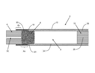
The smoking article 2 shown in Figure 1 has an overall length of 70 mm, a
diameter of
7.9 mm and comprises a combustible heat source 4 according to the invention,
an aerosol-
forming substrate 6, an elongate expansion chamber 8 and a mouthpiece 10. As
shown in
Figure 1, the combustible heat source 4, aerosol-forming substrate 6, elongate
expansion
chamber 8 and mouthpiece 10 are in abutting coaxial alignment and are
overwrapped in an
outer wrapper of cigarette paper 12 of low air permeability.
The combustible heat source 4 is 11 mm in length and 7.8 mm in diameter, and
has a
density of about 0.84 g/cm3. The combustible heat source 4 comprises a central
airflow channel
16 of circular cross-section that extends longitudinally through the
combustible heat source 4. A
substantially air impermeable, heat resistant coating (not shown) having a
thickness of
80 microns is provided on the inner surface of the central airflow channel 16,
which is 2 mm in
diameter.
The aerosol-forming substrate 6, which is 10 mm in length, 7.8 mm in diameter
and has
density of about 0.8 g/cm3, is located immediately downstream of the
combustible heat source
4. The aerosol-forming substrate 6 comprises a cylindrical plug of homogenised
tobacco
material 18 comprising glycerine as an aerosol former and circumscribed by
filter plug wrap 20.
The homogenised tobacco material 18 consists of longitudinally aligned
filaments of extruded
tobacco material.
A combustion resistant wrapper 22 consisting of a tube of aluminium foil
having a
thickness of 20 microns, a length of 9 mm and a diameter of 7.8 mm surrounds
and is in contact
with a rear part 4b of the combustible heat source 4 of 4 mm in length and an
abutting front part
6a of the aerosol-forming substrate 6 of 5 mm in length. As shown in Figure 1,
a front part of
CA 02878143 2014-12-30
WO 2014/006078
PCT/EP2013/064006
- 19 -
the combustible heat source 4 of 7 mm in length and a rear part of the aerosol-
forming
substrate 6 of 5 mm in length are not surrounded by the combustion resistant
wrapper 22.
The elongate expansion chamber 8, which is 42 mm in length and 7.8 mm in
diameter, is
located downstream of the aerosol-forming substrate 6 and comprises a
cylindrical open-ended
tube of cardboard 24. The mouthpiece 10 of the smoking article 2, which is 7
mm in length and
7.8 mm in diameter, is located downstream of the expansion chamber 8 and
comprises a
cylindrical plug of cellulose acetate tow 26 of very low filtration efficiency
circumscribed by filter
plug wrap 28. The mouthpiece 10 may be circumscribed by tipping paper (not
shown).
In use, the consumer ignites the combustible heat source 4 and then draws air
through
the central airflow channel 16 downstream towards the mouthpiece 10. The front
part 6a of the
aerosol-forming substrate 6 is heated primarily by conduction through the
abutting non-
combusting rear part 4b of the combustible heat source 4 and the combustion
resistant wrapper
22. The drawn air is heated as it passes through the central airflow channel
16 and then heats
the aerosol-forming substrate 6 by convection. The heating of the aerosol-
forming substrate 6
releases volatile and semi-volatile compounds including the aerosol former
from the tobacco
material 18, which are entrained in the heated drawn air as it flows through
the aerosol-forming
substrate. The heated air and entrained compounds pass downstream through the
expansion
chamber 8, cool and condense to form an aerosol that passes through the
mouthpiece into the
mouth of the consumer at about ambient temperature.
To make the smoking article 2, a rectangular piece of the combustion resistant
wrapper
22 is glued to cigarette paper 12. The combustible heat source 4, the plug of
the aerosol-
forming substrate 6 and the expansion chamber 8 are suitably aligned and
positioned on the
cigarette paper 12 with the attached combustion resistant wrapper 22. The
cigarette paper 12
with the attached combustion resistant wrapper 22 is wrapped around the rear
part 4b of the
combustible heat source 4, the aerosol-forming substrate 6 and the expansion
chamber 8 and
glued. The mouthpiece 10 is attached to the open end of the expansion chamber
using known
filter combining technology.
Combustible heat sources according to the invention may be produced in
accordance
with Example 1 or Example 2 below. Example 1 describes a pressing process for
producing a
combustible heat source and Example 2 describes an extrusion process.
EXAMPLE 1 - Pressing
Combustible heat sources according to the invention were prepared by mixing
the
components shown in Table 1 below to form a granulate mixture.
CA 02878143 2014-12-30
WO 2014/006078
PCT/EP2013/064006
- 20 -
COMPONENT FUNCTION AMOUNT (grams)
Unpyrolysed carbon powder Fuel 135
Calcium peroxide (75% purity) Ignition aid 150
Carboxymethyl cellulose Organic polymeric binder 5
Mono-potassium citrate Carboxylate burn salt 5
Exfoliated montmorillonite clay Non-combustible inorganic binder 5
Deionised water Solvent 196
Table 1
800 mg of the mixture was introduced into the cylindrical mould cavity of a
pressing
mould using a funnel and the mixture was pressed within the mould cavity using
a manual press
to obtain a cylindrical heat source having a length of 13 mm. The pressed heat
source was
removed from the mould cavity and then dried at about 100 C for about 1 hour
and conditioned
at about 22 C, 30 percent relative humidity, for about 12 hours. The density
of the heat source
was between about 0.80 g/cm3 and about 0.85 g/cm3.
The temperature of a combustible heat source 4 produced according to Example 1
during ignition and combustion of the combustible heat source 4 was measured
using a
thermocouple inserted into the middle of the combustible heat source. The
results are shown in
Figure 2. To generate the profile shown in Figure 2, the upstream end of the
combustible heat
source was ignited using a conventional yellow flame lighter.
For the purposes of comparison, the temperature of a prior art heat source
including only
an organic binder material was measured under similar experimental conditions.
The prior art
heat source was produced in accordance with Example 1, but with the three
binder components
replaced with 15 grams of carboxymethyl cellulose. The density of the prior
art heat source was
about 0.84 g/cm3. The results are also shown in Figure 2.
As can be seen from Figure 2, the combustible heat source 4 of the invention
including
the binding agent comprising a combination of organic and inorganic binder
materials achieved
a higher burning temperature and a longer burn lifetime than the prior art
heat source including
only organic binder material. These results demonstrate an improvement in the
burning
properties provided through the use of the improved binding agent including
the specific
combination of three binder components, as described above. In particular,
these results
demonstrate that the use of the improved binding agent including the specific
combination of
three binder components surprisingly results in the combustible heat source 4
of the invention
having a longer burn lifetime than the prior art heat source even though the
combustible heat
CA 02878143 2014-12-30
WO 2014/006078
PCT/EP2013/064006
-21 -
source 4 of the invention comprises less combustible organic material than the
prior art heat
source.
During ignition of a sample of combustible heat sources 4 produced according
to
Example 1, no sparks or flames were visible for any heat source. In contrast,
during lighting of
a corresponding sample of prior art heat sources including only organic binder
material, sparks
or flames were observed during lighting for at least two thirds of the heat
sources in the sample.
This provides a qualitative indication of the improved integrity of the
combustible heat sources
of the invention including the three binder components, compared to the prior
art heat sources
including only organic binder material.
In order to more quantitatively demonstrate the improved integrity of the
combustible
heat source produced according to Example 1, a "drop off" test was conducted
on a sample of
heated smoking articles incorporating one of the combustible heat sources
prepared
according to Example 1. A corresponding drop off test was conducted on a
sample of
20 heated smoking articles of the same construction but including a prior art
heat source,
15 comprising only organic binder material.
In each case, the combustible heat sources were first conditioned for 12 hours
at 22 C
and 50 percent relative humidity. Each heat source was then inserted into a
heated smoking
article, wherein the same construction of heated smoking article was used for
all samples for
the purposes of comparison. For each tested smoking article, the smoking
article was mounted
20
on a holding bar on a metal block. The mounted smoking article was connected
to a vacuum
system for performing puffs by drawing air through the smoking article,
wherein the vacuum
system includes a vacuum pump capable of producing 177.8 mmHg during a puff,
with a flow
rate of 2 litres per minute.
The combustible heat source was ignited using a yellow flame lighter. Each lit
smoking
article was then subjected to four cycles of dropping, each cycle comprising
twenty drops
wherein the metal block on which the smoking article was mounted was dropped
by a height of
3.81 cm. The cycles of dropping were actuated immediately after lighting, 3
minutes after
lighting, 6 minutes after lighting and 9 minutes after lighting. After each
cycle, a two second puff
was taken on the smoking article.
For each dropping cycle, the number of drop offs was observed, wherein a "drop
off" is
constituted by at least one sixth of the length of the combustible heat source
falling away from
the smoking article. For the sample of 20 cigarettes, the percentage drop off
rate was
calculated for each cycle, by dividing the number of drop offs during that
cycle by the total
number of smoking articles, that is 20, and then multiplying this value by
100.
During the test conducted with the sample of 20 smoking articles incorporating
combustible heat sources according to the invention produced according to
Example 1, a drop
CA 02878143 2014-12-30
WO 2014/006078
PCT/EP2013/064006
- 22 -
off rate of 0 percent (0%) was observed for all of the dropping cycles. No
drop offs were
observed during the entire experimental test.
During the comparative tests conducted with the sample of 20 smoking articles
incorporating prior art heat sources including only organic binder material, a
drop off rate of at
least 20 percent was observed after the first dropping cycle conducted
immediately after ignition
and a drop off percentage of at least 40 percent was observed after the second
dropping cycle
conducted 3 minutes after ignition. No further drop offs were typically
observed during the
dropping cycles carried out at 6 and 9 minutes after ignition. These results
demonstrate that the
integrity of the prior art heat sources during burning is less than the
integrity of the combustible
heat sources of the invention. The prior art heat sources were observed to
become more prone
to cracking and breakage during burning than the combustible heat source of
the invention,
incorporating the improved binding agent.
EXAMPLE 2 ¨ Extrusion
Combustible heat sources according to the invention having similar properties
to those
exhibited by the combustible heat sources prepared in accordance with Example
1 were
prepared as described below.
The same components shown in Table 1 were first mixed in a high shear kneader
mixer
to form a granulate mixture. Using a ram extruder, the granulate mixture was
then extruded at a
speed of 60 cm3/min through a die having a central die orifice of circular
cross-section with a
diameter of 8.7 mm to form cylindrical rods having a length of about 20 cm to
about 22 cm and
a diameter of about 9.1 mm to about 9.2 mm.
The cylindrical rods were dried at about 22 C, 45 percent relative humidity,
for about
24 hours. After drying, the cylindrical rods were cut to form individual
combustible heat sources
having a length of about 13 mm and a diameter of about 7.8 mm. The individual
combustible
heat sources were then dried at about 100 C for about 1 hour and conditioned
at about 22 C,
percent relative humidity, for about 12 hours. The dried individual heat
sources had a mass
of about 800 mg.