Note: Descriptions are shown in the official language in which they were submitted.
CA 02878335 2015-01-05
Method and apparatus for feeding electric energy into an electric supply grid
The present invention relates to a method for controlling a generator of
electric energy which is
connected to an electric supply grid in a grid connection point. In addition,
the present invention
relates to such a generator of electric energy.
Feeding electric energy into an electric supply grid, such as the European
grid or the US power
grid, is generally known. The electric supply grid as described below refers
to the widely ac-
cepted AC voltage grid. This does not exclude the presence of DC voltage
sections in the grid.
Likewise, frequency-independent aspects may generally also refer to a DC
voltage grid. Histori-
cally, energy is fed into an electric supply grid with a large power station
that drives a synchro-
nous generator using primary energy, such as coal, nuclear energy or gas.
Depending on the
number of pole pairs and the speed of the synchronous generator, this
generator feeds into the
supply grid with a certain frequency. The synchronous generator may be
technically controlled
so as, for example, to adjust the output. However, such adjustment process can
take a long
time.
With changing situations in the supply grid that is to be fed, the physical
reaction of the syn-
chronous generator often causes a change in the grid condition, at least for a
short time. For
example, the speed of the synchronous generator increases if the supply grid
is not able to take
the power completely that is or can be provided by the synchronous generator.
This excess
power then accelerates the synchronous generator, which results in an
increased feeding
frequency. Accordingly, the frequency in the supply grid may increase.
When feeding into a supply grid, the grid stability must also be taken into
account. The loss of
grid stability, i.e., the loss of the stability of the supply grid, may result
in the feeding generator
being powered off. Such a loss of stability, which is referred to as such and
abbreviated as
"LOS" among German-speaking experts, describes physical processes that no
longer allow for
a continued operation and must be terminated by cutoffs. In the case of power
plants, this
affects their output, and can thus contribute to an escalation of the so-
called deficit output. In
the worst case, this loss of stability leads to a total energy system failure
due to error cascading
and deficit accumulation. Such total failures are very rare; however, one
occurred in Italy on 24
September 2004.
CA 02878335 2015-01-05
- 2
Loss of grid stability, i.e. the so-called loss of stability, is a phenomenon
which involves at first a
loss of angular stability that may eventually cause a loss of voltage
stability.
Overcurrents to be achieved are determined as stability criteria, which can be
provided in the
case of a loss of stability. This requires the systems to have a certain
design. A new power
plant, in particular a power plant that is to be newly built, is thus
coordinated to the supply grid
as is represented on the grid connection point to which the power plant is to
be connected.
When connecting large power plants to an electric supply grid, the short
circuit current ratio is
an important criterion; this is known among German specialists as "short
circuit radio" and
abbreviated as "Scr". This short circuit current ratio is the ratio of the
short circuit power to the
connected load. Short circuit power is the power that the respective supply
grid on the consid-
ered grid connection point, to which the power plant is to be connected, can
provide in the case
of a short circuit. The connected load is the connected load of the power
plant that is to be
connected, in particular the nominal capacity of the generator that is to be
connected.
To secure reliable operation, i.e., to avoid a loss of stability to the
greatest extent possible,
power plants are generally designed for the respective grid connection point
in such a way that
the short circuit current ratio is higher than 10, normally even higher than
15. The supply grid
can then provide a relatively high short circuit power on the grid connection
point. That means
that the grid has a low grid impedance and is referred to as a strong grid.
In the case of a weak grid, in other words, in the presence of a high
impedance, feeding is only
possible with a low connected load, i.e., only a power plant with a low
connected load can be
connected. This usually leads to the fact that either a new power plant cannot
be connected to
such a grid connection point, or the grid has to be changed, particularly by
equipping it with
further, more powerful lines. This is generally referred to as grid
reinforcement.
For feeding electric energy by decentralized generation units, in particular
wind power installa-
tions, the problem of the grid's loss of stability is basically unknown.
Already at the end of the
nineties, first proposals were made to ensure that wind power installations
also contribute to the
electric support of the grid. This, however, does not take into account the
cause of a loss of
stability, in particular that feeding into the supply grid can cause a loss of
stability.
CA 02878335 2015-01-05
- 3
For example, the German patent application US 6,891,281 describes a method in
which wind
power installations can change and, in particular, reduce their power feed-in
depending on the
grid frequency. US 7,462,946 suggests that in the case of a grid failure,
particular in the case of
a short circuit, a wind power installation limits the power that it feeds-in
instead of being discon-
nected from the grid in order to achieve a grid support. US 6,965,174
describes a method for
supporting the grid by means of a wind power installation that, depending on
the grid voltage,
adjusts a phase angle of the fed-in electricity, and thus feeds reactive power
into the grid de-
pending on the voltage so as to support the grid. US 6,984,898 also relates to
a method for
supporting the grid by means of a wind power installation in which the wind
power installation
reduces, depending on the grid voltage, the power that is to be fed into the
grid, particularly so
as to avoid a disconnection from the grid in order to support the grid by
means of a wind power
installation.
The fact that such decentralized generation units, such as wind power
installations, may be the
underlying cause for the loss of stability in the grid has not been taken into
account. In the
essay "Loss of (Angle) Stability of Wind Power Installations" by V. Diedrichs
et al., submitted for
and presented at the "10th International Workshop on Large-Scale Integration
of Wind Power
into Power Systems as well as on Transmission Grids for Offshore Wind Farms,
Aarhus (Den-
mark), 25 - 26 October 2011". There, reference was basically made to the
problem that the loss
of stability in the grid can basically also occur for wind power installations
that are connected to
the supply grid for feed-in. This essay essentially raises awareness of the
problem. Reference
is expressly made to this essay and its content. In particular, its technical
explanations also
apply to the present application.
Basically, findings, experience and other knowledge of the operation and
connection of large
power plants to the electric supply grid cannot be transferred to wind power
installations, includ-
ing large wind parks with numerous wind power installations that are connected
to the supply
grid for feed-in. The responsible expert who connects a power plant to a
supply grid in order to
operate it there is already a different expert from the one wanting to connect
a wind power
installation to the supply grid in order to operate it there. Wind power
installations - and much of
the following also applies to decentralized generation units - depend on wind
and must therefore
take a fluctuating energy source into account; they usually do not feed into
the supply grid with
a synchronous generator that is directly coupled to the grid, but use a
voltage-based inverter
instead; they have a different size than large power plants, whereby their
nominal capacity is
usually 3 powers of ten below that of a large power plant; they are usually
subject to other
CA 02878335 2015-01-05
- 4 -
political laws which often ensure the acceptance of the provision of power by
the operators of
electric supply grids; they are usually decentralized; and, they usually feed
into a medium-
voltage grid, whereas large power plants usually feed into an extra high
voltage grid.
The German Patent and Trademark Office has found the following prior art in
the priority appli-
cation for the present application: DE 10 2011 053 237 Al, WO 2010/060903 Al,
US
2010/0148508 Al, DE 10 2007 044 601 Al, DE 10 2007 018 888 Al, US 2010/0237834
Al as
well as the article by Volker Diedrichs et al., "Loss of (Angle) Stability of
Wind Power Plants -
The Underestimated Phenomenon in Case of Very Low Short Circuit Ratio ¨".
The object of the present invention is to address at least one of the problems
mentioned above.
In particular, a solution is to be proposed in which decentralized generation
units, such as wind
power installations, can be operated in such a way as to consider the
phenomenon of the
supply grid's loss of stability. In particular, a solution is to be proposed
in which decentralized
generation units, such as wind power installations or wind parks, contribute
to grid stability by
preventing a loss of stability with regard to the grid. An alternative
solution should at least be
provided.
In accordance with the invention, a method is proposed according to Claim 1.
According to this,
a generator of electric energy connected to an electric supply grid on a grid
connection point is
controlled. As a purely precautionary measure, it is pointed out that a
generator of electric
energy converts existing energy to electric energy, which is here simply
referred to as genera-
tion. According to the proposed control method, at least one grid
characteristic of the electric
supply grid is incorporated with regard to the grid connection point. The grid
characteristic
incorporated here is in particular the grid's behavior with regard to
stability under different oper-
ating conditions of the grid and/or under different conditions for feed-in or
boundary conditions
for feed-in. In particular, grid characteristics are incorporated describing
the supply grid behavior
in the case of deviations from the nominal operating point.
In addition, it is proposed to feed electric power into the electric supply
grid based on this incor-
porated grid characteristic. Thus, controlling the feed-in depends on the
predetermined grid
characteristic. This is to be distinguished from the technical design of the
generator, in which
the control does not take the grid characteristics into account. Control of
the feed-in depending
on the incorporated grid characteristics is also to be distinguished from the
control depending
on actual grid conditions. Equally, it is also advantageous, in addition to
the control of the feed-
CA 02878335 2015-01-05
- 5
in depending on the incorporated grid characteristic, to design the generator
according to the
incorporated grid characteristic and to perform the control depending on grid
conditions, which
is, however, not the primary subject matter of this application.
Pursuant to the invention, it was recognized that in particular considering
the grid characteristic
when designing the connected generator or the generator that is to be
connected may be an
incomplete consideration. This applies in particular to decentralized
generation units or decen-
tralized generators that are able to adapt dynamically to new situations.
However, an adaption
to new situations, i.e., to changed conditions in the supply grid, carries the
risk that any current
problems in the supply grid might not be completely resolved. Only if at least
one previously
incorporated grid characteristic is considered can the feed of electric power
into the electric
supply grid be proactively controlled. Such proactive control primarily aims
at the early avoid-
ance, or at least detection, of stability issues in the supply grid,
particularly with regard to a loss
of stability.
It is proposed to apply this control method preferably to a so-called
decentralized generator
and/or a wind power installation or a wind park containing several wind
plants. A wind power
installation is usually a decentralized generator, since it is installed at
remote locations that
depend in particular on wind conditions, and, due to their connected load,
they cannot be
viewed as a central energy source, as opposed to large power plants. The same
usually also
applies to a wind park with several wind power installations. In addition,
wind power installations
and small wind parks are basically connected to an existent supply grid. A
connecting line or
several connecting lines might be provided for a connection to this supply
grid. However, the
basic structure of the supply grid remains unchanged.
Until now, it had been assumed that a connection of such decentralized
generators had no
major impact on the basic characteristic and the basic structure of the
respective supply grid. It
was examined whether the respective grids had enough capacity for a connection
of the decen-
tralized supplier, i.e., whether they had sufficient capacity to transport the
additional power to be
fed in and which was expected from the decentralized generator. In particular,
aspects of the
grid stability established through the feed-in of this generator have
practically been ignored. In
particular, with regard to such decentralized generators, the extent to which
their feed-in of
electric energy could cause a loss of stability of the supply grid has been
ignored. The present
method is therefore directed in particular at such decentralized suppliers, in
particular wind
power installations and wind parks.
CA 02878335 2015-01-05
- 6 -
The feed-in, particularly by decentralized generators, is preferably performed
by means of a
voltage inverter. With such feed-in by means of a voltage inverter, an
inverter is used to which
the energy that is to be fed is provided, e.g., on a DC intermediate circuit,
and the voltage
inverter produces a voltage change signal that is as sinusoidal as possible.
This voltage
change signal, often by using a line choke, will lead to power that is to be
fed into the supply
grid. Further voltage transformations by means of one or several voltage
transformers can be
provided.
Here, a so-called full power conversion concept is particularly proposed,
whereby all of the
electric power that is to be fed is done so into the supply grid by means of
this voltage inverter.
Losses are not considered here. With regard to wind power installations, other
concepts with a
voltage inverter are to be considered, whereby the voltage inverter controls
the feed-in of elec-
tric power indirectly via the control of a generator that generates the power,
in particular a
double-feed asynchronous generator.
Using a voltage inverter to feed-in electric power of a supply grid, in
particular according to the
full power conversion concept, is essentially different from feeding electric
power through a
large power plant. The voltage inverter can and/or has to constantly adapt the
voltage amplitude
and frequency of its feed-in, depending on the grid condition. As a result, it
is able to react
promptly to changes in the grid. This bears the risk that it becomes unstable
quickly if this
prompt reaction is performed incorrectly. It is this problem in particular
that is addressed by this
invention.
According to one embodiment, it is proposed that the generator be controlled
in such a way that
it is controlled in an operating point that depends on the incorporated grid
characteristics. In
particular, it not only depends on these incorporated characteristics, but
also on the voltage
amplitude and the frequency in the supply grid, namely on or near the grid
connection point.
Furthermore, it may depend on the currently fed-in active power and/or the
currently fed-in
reactive power. This results at first in a nominal operating point designed
for this grid connection
point with the respective incorporated grid characteristic and for the
specific generator. With
changing conditions of the grid or of the feed-in, another operating point may
be selected which
takes the previously incorporated grid characteristic into consideration. The
generator's operat-
ing point on the grid connection point is preferably specified by the active
power and/or the
reactive power that the generator feeds into the supply grid.
CA 02878335 2015-01-05
- 7
According to one embodiment, it is proposed that at least one control
characteristic, which
depends on the incorporated grid characteristic, be applied to set the
operating point. Such a
control characteristic can also be multidimensional, i.e., it can depend on
several input parame-
ters and/or comprise several parameters for setting at the same time. In
particular, the control
characteristic, depending on the grid voltage on the grid connection point,
determines the reac-
tive power and/or the active power that is to be fed-in. The control
characteristic is created on
the basis of the at least one incorporated grid characteristic. In particular,
the characteristic is
selected so as to ensure that the operation of the generator does not lead to
a loss of stability of
the supply grid.
According to one proposal, it is provided to use a nonlinear controller, in
particular a controller
with a nonlinear and/or inconstant controller characteristic. In particular,
it is proposed to avoid
using a PID controller as the exclusive controller. It has been recognized
that a PID controller is
insufficient for some requirements and that it does not meet the requirements
with optimum
parameterization. A nonlinear controller can better adapt to the system that
is to be controlled.
A nonlinear controller may be a fuzzy controller, a controller that is based
on a neural grid, a
multiplying controller, a controller with a hysteresis function and/or a
controller using a dead
time characteristic.
According to one embodiment, a controller is used that results in the
operating point being
adjusted according to the control characteristic. For example, such a control
characteristic may
specify the fed-in reactive power Q depending on the fed-in active power P and
the voltage U in
the grid, as described by the formula Q=f(P,U).
Preferably, incorporating at least one grid characteristic, which can also be
performed by calcu-
lating the grid characteristics, comprises the incorporation of a connection
between fed-in
reactive power and a grid voltage on the grid connection point. In addition or
alternatively, it
comprises the incorporation of a connection between the fed-in active power
and the grid volt-
age on the grid connection point. Preferably, it comprises the incorporation
of a connection
between fed-in active power, fed-in reactive power and the grid voltage on the
grid connection
point, so that in this case, a three-dimensional connection is incorporated.
Thus, a connection
between reactive power, active power and grid voltage is incorporated, which
reveals the supply
grid's behavior with regard to this grid connection point, and may serve as a
basis for the control
of the generator when feeding into the supply grid.
CA 02878335 2015-01-05
- 8
According to one embodiment, it is proposed that incorporating the grid
characteristic comprise
the incorporation of a stability boundary. Such a stability boundary can be
specified as a func-
tion of the grid voltage on the grid connection point, depending on the fed-in
reactive power and
the fed-in active power. This boundary is defined by three parameters, and can
be illustrated
three-dimensionally. In such a three-dimensional representation, the stability
boundary basical-
ly has a curved or arched surface, namely a boundary surface. Accordingly, the
respective
operating points, and thus the characteristic provided by the operating
points, are chosen on the
stable side of the stability boundary. According to the expected dynamics of
the supply grid
and/or the generator, and thus in the case of a wind power Installation also
of the wind, a small
or great distance of the respective operating point from the stability
boundary may be selected.
According to one embodiment, it is proposed that the at least one incorporated
grid characteris-
tic be calculated according to a model. For this purpose, a grid analysis of
the supply grid is first
performed, considering, for example, the line system, transformers in the
supply grid, switching
equipment, consumers, and generators. A transformer is hereinafter also simply
referred to as a
transformer. In particular, its values are entered into a calculation or
simulation program. The
grid analysis is specifically performed for the existent or planned grid
connection point. There-
fore, individual elements may be disregarded in the grid analysis if they are
evidently no longer
of significant relevance for the grid connection point. Respective grid
sections can be consid-
ered through the use of equivalent models, in particular using substitute
impedances. Then, a
model of the supply grid is created, based on the grid analysis; this model
can be edited and
tested with a respective software for a grid analysis model. Next, in
particular with such analy-
sis software, and based on the grid model for the concrete grid connection
point, a simulation of
different operating points is performed, and the simulation results are
recorded. The result of
the simulation is the at least one incorporated grid characteristic. In
particular, a plurality of the
simulated individual operating points are determined or taken as a basis for
this purpose.
It is noted that the term "supply grid" may also be used in its simple form
"grid" or "grid".
Preferably, the stability boundary resulting, for example, from the above
simulation, can be
stored in a table. In addition or alternatively, it can also be approximated
with an analytical
function. Intermediate values that were not recorded may also be determined by
interpolation.
According to one embodiment, it is proposed that, when incorporating the at
least one grid
characteristic, characteristics, or at least one characteristic, of the
generator are (or is) to be
CA 02878335 2015-01-05
- 9
considered as well, and that a short circuit current ratio is to be
incorporated. The grid charac-
teristics of the connection node are also incorporated on this power supply in
consideration of
the characteristics of the generator. Preferably, it is proposed that the
generator be controlled
with a short circuit current ratio of <6. Preferably, the short circuit
current ratio is hereby <4, and
in particular <2. Thus, a control method is suggested for a short circuit
current ratio that is
smaller than usual. This often requires that this specific design be
implemented or at least
accepted. It is deliberately proposed to feed into a weak grid, namely in
particular with a gener-
ator, the connected load of which is large compared to the short circuit power
of the grid with
regard to the connection point, namely larger than one sixth, larger than a
quarter or even larger
than half the short circuit power of the grid for this connection point. It
has thereby been recog-
nized that using a wind power installation with a voltage source converter can
simply be referred
to as a voltage converter, in particular with a full converter structure, the
operation of which is
facilitated in a weak grid. It is deliberately accepted that by choosing or
accepting a low short
circuit current ratio, operation will occur near a stability boundary. It has
been recognized that a
control with a voltage converter can secure a respective control, in
particular a respective fast
and accordingly precise control of the feed-in. As a result, the grid
connection points that have
so far been regarded as unsuitable can now be used to connect a generator.
According to one embodiment, it is proposed that the operating point of the
generator be select-
ed with a predetermined stability reserve with regard to the stability
boundary. Therefore, a
specific selection of the operating point is proposed, so as to secure
stability. This is particularly
different from a concept foreseeing a design with a very high short circuit
current ratio, whereby
a concrete operating point was not selected. In other words, an overly
cautious design is
avoided. The operating point is selected in a certain stability reserve, and
thereby led with this
stability reserve during control. With changing grid conditions or boundary
conditions in the
grid, which for example temporarily reduce the stability reserve, the
operating point is adapted
accordingly so as to observe again the stability reserve.
According to one embodiment, the stability reserve is a minimum permissible
distance of the
operating point to the stability boundary, if the values describing the
operating point and the
stability boundary are standardized. For example, the stability boundary and
also the operating
point can be defined by the value of the fed-in reactive power, the fed-in
active power, and the
voltage on the grid connection point. Then, the active power can be
standardized to the nominal
capacity of the generator, and the reactive power can also be standardized to
the nominal
capacity of the generator. The voltage is preferably standardized to the
nominal voltage. As a
CA 02878335 2015-01-05
- 10
result, the values are without unit, and can be compared with each other,
which is usually not
easily possible with different units.
In the mentioned example, the stability boundary is a curved surface in a
space, namely in the
space which is formed if the reactive power, the active power and the voltage
form a Cartesian
coordinate system. In this illustrative example, the stability reserve can be
another curved
surface, which has, for example, a distance of 0.1 in principle. The stability
reserve then, also
vividly described, forms something similar to a buffer layer.
In mathematical terms, such a minimum permissible distance can be calculated,
for example, by
the root of the sum of the squares of the differences of each individual
standardized value.
Preferably, different operating points are to be provided for different
stability reserves. For
example, the stability reserve of an optimum operating point with nominal
voltage in which rated
active power but no reactive power is fed-in may be selected as small. With
other operating
points, it may be useful to provide a greater safety distance. The buffer
layer, identified as such
for illustrative purposes, then does not have a consistent thickness. Such a
varying or constant
distance is preferably at least 0.05, 0.1 or in particular at least 0.2.
Preferably, during operation, the stability reserve of the actual operating
point is constantly
observed and, in particular, the operating point is changed if the distance to
the stability reserve
is reduced, especially if it falls below the value of the respective stability
reserve. This observa-
tion can be made online or quasi-online, i.e., with small time differences
between the observa-
tion times and/or through a dynamic observer with a slight time delay. This
can be used to
respond quickly and at very short notice to changes which are relevant to
stability, and thus to
secure a stable operation even near the stability boundary.
Furthermore, a wind power installation is proposed which comprises an electric
generator
coupled with an aerodynamic rotor to generate electric energy from wind, and
comprising a
frequency converter apparatus to feed the electric energy into the supply
grid, whereby the wind
power installation is controlled according to at least one method of the above
described embod-
iments. Here, the wind power installation is a generator and is controlled to
feed into the supply
grid. Preferably, the frequency converter apparatus comprises a rectifier
which rectifies the
alternating voltage of the electric generator and comprises an inverter to
transform the DC
voltage into AC voltage to be fed into the supply grid. Such a frequency
converter apparatus in
CA 02878335 2015-01-05
- 11
which - disregarding losses - all the electric energy produced is completely
led through the
rectifier and through the inverter can also be referred to as a full power
conversion concept or
full power conversion topology. Instead of a rectifier, it is also possible to
provide a combination
of several rectifiers, and/or instead of a single inverter, several inverters
can be provided which,
in each case, only invert a part of the energy.
Preferably, the wind power installation is connected to the grid connection
point, the electric
energy produced is fed into the supply grid on this grid connection point, and
a short circuit
current ratio of <10, preferably <6, even more preferably <4, and in
particular <2) is selected.
Such a selection of a very small short circuit current ratio is made possible
together with the
respective control of the generator, namely the wind power installation,
during the feed-in.
Therefore, wind power installations with high connected loads, in particular
high nominal capaci-
ties, can be connected to comparatively weak grids, and thus can often be set
up at remote
locations. As a result, it is now possible to use installation sites which
have been unsuitable up
to now, since their supply grid would have had to be adjusted significantly.
Preferably, a threatening loss of stability on the grid connection point is
detected and/or shown.
This is to avoid an interruption of the feed-in, or to prepare the generator
for a quick return
feeding in case of a loss of stability.
The threatening loss of stability is preferably detected or shown if the
amount of a partial dis-
charge of grid voltage exceeds a predetermined active power limit according to
the fed-in active
power.
By taking the partial discharge of the grid voltage according to the active
power into considera-
tion, a grid sensitivity can be detected, and the result of the discharge can
be used as an indica-
tion to select a more stable operating point.
Preferably, a threatening loss of stability is detected or shown on the basis
of an amount of a
partial discharge of grid voltage, and according to the fed-in active power,
if this amount of
partial discharge exceeds a predetermined reactive power limit. Here again,
the grid sensitivity
is considered or determined.
Preferably, the threatening loss of stability is detected or shown by
analyzing a 3-phase voltage
of the supply grid according to the method of a symmetrical component, whereby
a threatening
CA 02878335 2015-01-05
- 12 -
,
loss of stability is assumed if the amount of a co-voltage component is larger
than a co-voltage
limit. In addition and alternatively, it is proposed to assume a threatening
loss of stability if the
amount of a counter voltage component is larger than a counter voltage limit.
The known
method of the symmetrical components takes asymmetries particularly into
consideration. If the
amount of the co-voltage component is monitored, it is monitored to the
extent, in simple terms,
that the symmetrical portion of the 3-phase voltage system exceeds or falls
below a value.
Through a consideration of a counter voltage component, it can be recognized
in particular
whether an asymmetry value is too high and indicates a fault in the grid,
which can be expected
to result in a loss of stability.
The amount of a difference between a reference frequency and a nominal
frequency can also
be considered. A threatening loss of stability can be assumed if the
difference exceeds or falls
short of a predetermined frequency limit or exceeds this by its absolute
value.
Equally, a wind park with several wind power installations is proposed,
whereby each wind
power installation comprises an aerodynamic rotor, an electric generator, and
a frequency
converter apparatus, as described above. Furthermore, the operation of the
park is proposed
by means of a method, as described above, according to one of the embodiments.
In this
respect, the whole park is regarded and operated as a generator in the meaning
of the de-
scribed methods. In particular, the short circuit current ratio relates to the
short circuit power
ratio of the supply grid of the connection point with regard to the connected
load of the wind
park, in particular the sum of the nominal capacities of all wind power
installations of the rele-
vant wind park. It is also proposed, according to one embodiment, to design
this wind park so
that it has a low short circuit current ratio, in particular <10, <6, <4, and
in particular, preferably
<2. Particularly by combining several wind power installations into one wind
park, large con-
nected loads can be achieved, as opposed to individual wind power
installations. For this
purpose, a solution is now proposed allowing for a connection to a
comparatively weak grid with
regard to the connection point.
The grid sensitivity is important information for the provided control of the
generator in feeding
electric energy into the grid. This grid sensitivity is a characteristic
related in particular to the
grid connection point. It depends on the grid characteristics, such as the
grid topology, but also
on current grid conditions. It basically shows the degree of sensitivity with
which the voltage
reacts to influences on the grid connection point. If the generator is a wind
power installation or
a wind park with several wind power installations, the fluctuating wind
velocity is an external
CA 02878335 2015-01-05
- 13 -
factor which can, through the wind power installation, influence the grid, and
thus the voltage on
the connection point. Fluctuations of the wind velocity may have a strong or
weak influence on
the voltage on the connection point, and accordingly, there will be a strong
or weak grid sensi-
tivity with regard to the wind sensitivity.
Further, the current grid condition can have an impact on the sensitivity of
the voltage on the
grid connection point. For example, if the grid is less sensitive to external
factors, the voltage on
the grid connection point is more stable if the grid, in particular with
regard to the grid connec-
tion point, functions in a stable operating point. Conversely, the voltage on
the grid connection
point can be more easily influenced if the grid functions in a less stable
operating point, such as
an operating point at which, in the case of a wind power installation, the
plant is already sup-
porting the grid.
For example, a wind power installation can support the grid by feeding in
reactive power. Pref-
erably, it is therefore proposed that the grid sensitivity be determined in
accordance with the
partial discharge of the voltage on the grid connection point according to the
fed-in reactive
power. If there is a strong voltage change on the grid connection point with a
change in the fed-
in reactive power, the result is a high grid sensitivity, i.e., the voltage
can be more easily influ-
enced.
Alternatively or additionally, it is proposed to determine the grid
sensitivity on the basis of a
partial discharge of the voltage on the grid connection point of the power
generated by the wind
power installation, namely the active power. The active power generated and
fed in by the wind
power installation is a measurement for the existent wind velocity. If a
change of this fed-in
power leads to a strong voltage change on the grid connection point, there is
a high sensitivity
with regard to this power, and thus with regard to changes of the wind
velocity.
Preferably, the grid sensitivity is to be a sum of both of these partial
discharges, whereby the
summation can be weighted in order to consider or accept influences of varying
strength.
It is now preferably proposed to control the generator based on this grid
sensitivity. In particular,
a control behavior can or should be performed quickly or with amplification if
there is high sensi-
tivity and if, in the case of external interferences, a quick reaction is
required. On the other
hand, with weak sensitivity, a slow controller or a controller with little
power can be sufficient.
CA 02878335 2015-01-05
- 14
The load flow calculation described below is used to analyze stationary
operating conditions of
energy supply systems. The underlying basis is Fig. 9 of the respective grid
through its imped-
ances Z or its admittances Y (complex conductances).
The classical grid analysis determines the grid via Ohm's law with the
following linear equation
system in matrix notation, which describes a correlation for n-knots.
Y Y YU1-
_11 ¨12 ¨li ¨ln /1
--n
¨Y21 = = = Y22 Y2i = = = Y') ¨2 ¨)
= = = = =
= = = =
irn = = = Yn, Yõ; Yõõ IT
___... = = = - -
Y = U = I
Or in short: ¨ ¨ ¨ (linear equation system).
The aim is to determine voltages on each of the n-grid knots (-voltage
maintenance).
As the currents in the grids are unknown but the (planned) feed-ins and
electric falls are known,
the currents are expressed as outputs.
I..cS = - .iQi
u*
Representing the grid equations via outputs results in the formation of a non-
linear equation
system.
S7 =Pi - jQi= tUlUi +Y i2U2U7 = E yikuk
This non-linear equation system is solved numerically (usually by Newton's
method). When
solving the equation system numerically, it must be linearized. This is done
by the partial dis-
o .
CA 02878335 2015-01-05
1 ¨ 15 -
,
charges of the matrix elements on the basis of the unknown, namely still the
amplitude (U2...Un
and the angle ( 82...8, ) of the knot voltages here.
The matrix with the partial discharges is called a Jacobian matrix. In order
to solve the equation
system, this must be invertible, i.e., regular.
=
-
9 - (OP ) (()) = = = OP ( y
2-
) (0) -
Oi2
= = = ( DU,
.
2
k 062 ) th)õ \ 01,2 )
. .
i)P . . . ( OP
(()) A ,00)
,.--.sun
( i4; ) (7-1c. ) (_ 9 ,_
)
OU OUn
)
_
. =_- _______________________________________________ =
( 0(22 )(")oe
. = = (4(22 ) (0)
( i)(22 ) ((l) = - ( 0Q2 )(l))
:ALr(0)
our,
. .
(0) (0)
n )(U)
Q (()) (0Qõ ) (r(())
( ori2 ) ' ' ' Of --
- - - - - -
Jacobian matrix
The invention is described in more detail below by embodiments as examples
with reference to
the accompanying figures.
Fig. 1 shows a wind power installation in a perspective view.
Fig. 2 shows a schematic view of a wind power installation that is
connected to a grid, based
on a voltage control system (VCS).
Fig. 3 shows a schematic view of a circuit arrangement of a
voltage controlled feed-in of a
wind power installation into an AC grid.
Fig. 4 shows a schematic view of two wind power installations
connected to a grid over a
joint grid connection point.
CA 02878335 2015-01-05
- 16
Fig. 5 illustrates parameters that can influence the sensitivity of a wind
power installation
connected to a grid.
Fig. 6 shows a diagram analyzing the grid behavior on the grid connection
point as voltage
courses depending on the fed-in reactive power and fed-in active power.
Fig. 7 shows a sensitivity as a voltage change caused by changes of the
active power de-
pending on the fed-in and standardized reactive power and active power.
Fig. 8 shows a sensitivity as a voltage change caused by a change of the
reactive power
depending on the standardized reactive power and active power.
Fig. 9 shows a generalized grid illustration.
Below, identical reference signs for similar, but non-identical elements may
be provided, or they
can also be provided for elements that are only illustrated schematically or
symbolically, and
that may have different details, but which are not relevant for the respective
explanation.
Fig. 1 Shows wind power installation 100 with tower 102 and nacelle 104. Rotor
106 with three
rotor blades 108 and spinner 110 is located on nacelle 104. Rotor 106 is set
in operation by the
wind in a rotating movement, thereby driving a generator in nacelle 104.
Fig. 2 shows a schematic view of a wind power installation 1 connected to
electric supply grid 4
over grid connection point 2. Electric supply grid 4 is simply referred to as
grid 4 or grid 4,
whereby these terms are used synonymously.
Wind power installation 1 comprises generator 6, which is driven by the wind,
thereby generat-
ing electric energy. In one of the embodiments, generator 6 is an electrically
excited multiphase
synchronous generator 6 with 2 respectively star-shaped interconnected 3-phase
systems,
which is illustrated by means of the two star symbols in generator 6 of Fig.
2. The generated
alternating current, namely the 6-phase alternating current in the mentioned
example, is recti-
fied by rectifier 8, and transmitted as direct current via respective DC
current line 10, which can
comprise several individual lines, from nacelle 12 down tower 14 to inverter
16. Inverter 16
generates alternating current from the direct current, namely in the example
shown, a 3-phase
alternating current to be fed into grid 4. For this, the alternating current
generated by inverter 16
CA 02878335 2015-01-05
- 17 -
,
is stepped up by means of transformer 18 so as to be fed into grid 4 on grid
connection point 2.
Illustrated transformer 18 uses a star delta connection, namely and primarily
a star connection
and, secondarily, a delta connection, which is illustrated here merely as an
example of one
embodiment. The feeding into grid 4 can also include, besides the feeding in
of active power P,
the feeding in of reactive power Q, which is illustrated by arrow 20. For the
concrete feed-in,
inverter 16 is controlled by respective control unit 22, whereby control unit
22 can be structurally
combined with inverter 16. Fig. 2 is to illustrate the basic construction, and
the specific ar-
rangement of the individual elements can be chosen differently than
illustrated here. For exam-
ple, transformer 18 can be provided outside tower 14.
In particular, control unit 22 controls inverter 16 such that the manner of
the feed into the grid 4
is controlled. Tasks are thereby performed, such as adjusting the power that
is to be fed to the
situation in grid 4, in particular the frequency, phase and amplitude of the
voltage in the grid. In
addition, control unit 22 is designed to control the portion of the active
power P and reactive
power Q of the power that is actually fed into grid 4. Here, measurements are
performed in grid
4, in particular on grid connection point 2, and are evaluated accordingly.
Among other things,
the actual voltage in grid 4 is measured, in particular in the form of the
actual effective value of
the voltage, and compared with the default value for the voltage, namely
default value VsET.
Accordingly, the illustrated system, and in particular inverter 16 with
control unit 22, form a
voltage control system, which is abbreviated as VCS.
To control the generator of the wind power installation, power control block
24 and power eval-
uation block 26 are provided in the area of the nacelle. In the example of the
illustrated embod-
iment, power control block 24 particularly controls the excitation, namely the
excitation current
of the separately excited synchronous generator. Power evaluation block 26
evaluates the
power led to rectifier 8, and compares it with the output power released by
rectifier 8 over DC
current line 10 to inverter 16. The result of this evaluation is forwarded to
power control block
24.
Fig. 2 also illustrates that the system shown should have a voltage control
system for an intelli-
gent feed-in so as to operate the wind power installation as stably as
possible, in particular near
a stability boundary.
CA 02878335 2015-01-05
- 18
Fig. 3 illustrates the connection of wind power installation 1' to so-called
"weak grid 4". A weak
grid here refers to a grid with high impedance. This is illustrated in Fig. 3
by means of serial
impedance 5'. In addition, said serial impedance 5' was provided in a test
structure that corre-
sponds to the structure in Fig. 3, and which was used to examine the behavior
of wind power
installation 1' on weak grid 4'.
The structure of Fig. 3 assumes generator 6', which is driven by the wind and
provided as a
synchronous generator. The generated electric power of generator 6' is
rectified in rectifier 8',
and provided to inverter 16' on the input side on a DC link with intermediate
circuit capacitor 28'.
The structure shown compares DC line 10' with the DC intermediate circuit of
inverter 16' on the
input side to simplify the illustration. A DC line on the input side can
indeed be electrically
identical with an intermediate circuit, or a boost converter is provided on
the input side, which is
not explained in detail here. Rectifier 1' and inverter 16' can also be
physically separated from
each other, as already explained in Fig. 2 with regard to rectifier 8 and
inverter 16.
Finally, exciter control 24' is provided, which can be fed with energy from
the DC link that is
represented by intermediate circuit capacitor 28'. Said exciter control 24'
controls the excitation
current of separately excited generator 6' and basically corresponds to power
control block 24 of
Fig. 2.
Inverter 16' can feed in active power P and/or reactive power Q. Fig. 3 states
the voltage of
inverter 16' on the output side as voltage of the wind power installation
VwEc= For the feed-in,
this is stepped up by transformer 18, and then fed into grid 4' on grid
connection point 2'. Here,
grid 4' also comprises grid transformer 30'. The actual grid that starts after
grid transformer 30'
is specified with the reference sign 4". The voltage on grid connection point
2' is referred to as
grid voltage Vgrid.
To illustrate the weak grid, serial impedance 5' is shown in front of grid
connection point 2'. Said
serial impedance 5' exists only in this test structure or illustrating
structure, and indicates the
grid impedance. Therefore, the point shown directly next to transformer 18'
can also be referred
to as grid connection point 2". This differentiation between these two grid
connection points 2'
and 2" only results from this use of serial impedance 5', and usually does not
exist in this form in
real grids.
CA 02878335 2015-01-05
- 19
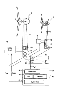
Fig. 4 shows another illustrative and schematic example, according to which
two wind power
installations 1 are connected to supply grid 4. Each wind power installation 1
is basically de-
signed as explained in Fig. 2, namely with generator 6, rectifier 8 and DC
line 10, which indeed
comprises at least two individual lines, namely for positive and for negative
current, which also
applies to DC line 10 of Fig. 2. Furthermore, wind power installation 1
comprises inverter 16 and
transformer 18. Access line 32 leads from each of the two wind power
installations 1 to a or the
grid connection point 2' on the wind power installation side. Thus, these two
wind power installa-
tions 1 shown as examples, which can be representative for a wind park with
far more than wind
power installations, feed their generated power jointly on this grid
connection point 2' on the
wind power installation side. The fed-in power P and the fed-in reactive power
Q, if present, is
then led to connection point 2' on the grid side, and fed into electric supply
grid 4.
The connection between grid connection point 2' on the wind power installation
side and con-
nection point 2" on the grid side cannot be ignored, and accordingly, the
voltage Vwp is reached
on the wind power installation side on grid connection point 2' on the wind
power installation
side, whereas the voltage Vgnd is reached on connection point 2" on the grid
side.
The voltage Vwp on the wind power installation side is determined and
evaluated in evaluation
block 34 for control. The evaluation is at first performed in such a way that
the measured values
are recorded with measuring block 36. The measurement results are forwarded,
amongst other
things, to stability control block 38, which can also be referred to as SVCS
(Stability Voltage
Control System) block. Stability control block 38 calculates a default value
Qset for the reactive
power that is to be provided. This reactive power that is to be reached is
then transferred as
respective default value to both wind power installations 1, and accordingly
would be transferred
to all wind power installations in one amount. This default value can be
transferred as an abso-
lute value, in particular if wind power installations 1 have the same size and
are subject to the
same wind conditions. However, it can also be provided as a default value,
such as a percent-
age value which refers to properties of the respective wind power
installation, e.g., as the nomi-
nal capacity of the relevant wind power installation.
Further, measuring block 36 transmits the values to observer block 40, which
calculates further
conditions on the basis of the determined measurement values, such as the fed-
in active power
or the fed-in reactive power, and transmits its results to system model block
42. Observer block
can also obtain or derive information on the power demand, if necessary.
CA 02878335 2015-01-05
- 20 -
,
The system model of system model block 42 is used to determine a maximum
active power
Pmax that is to be fed in, and to feed it to wind power installations 1. This
maximum active power
that is to be fed in can be provided as an absolute or relative value. It is
noted that the illustra-
tion of evaluation block 34 is to explain the structure. In general, it is not
necessary that evalua-
tion block 34 be physically designed as an independent apparatus.
The preset reactive power Qset and the maximum active power Pmax are then
transferred to the
FACTS control block 44 of each wind power installation 1. The term "FACTS" is
also used in the
German language and is an abbreviation for "Flexible AC Transmission System".
The FACTS
control block 44 then implements the default values and controls inverter 16
accordingly,
whereby it can also consider measurement values from the wind power
installation conditions.
In particular, but not exclusively, evaluation block 34 can provide stability
relevant defaults for a
stable feed into grid 4. In particular, an operating point can be set that is
favorable with regard to
the amount of energy to be fed or with regard to the amount of power and
stability. In particular,
an operating point with a stability reserve can be determined here. Here,
stability control block
38 can reach a stability reserve with regard to reactive power that is to be
fed-in by means of a
respective default of the reactive power C2set.
Fig. 5 illustrates the sensitivity of a wind power installation connected to a
grid and the corre-
sponding influencing factors. Grid block 50 of Fig. 5 is specified
representatively for the grid
behavior, namely on the grid connection point. Grid block 50 illustrates that
the grid can react to
influences due to a change in voltage. All influences are illustrated here as
changes of the
active power AP and changes of the reactive power AQ . Active power block 52
considers
influences of power changes, and reactive power block 54 considers influences
of changes in
reactive power. Active power block 52 shows a partial discharge of the voltage
on the basis of
the active power, and accordingly, reactive power block 54 shows a partial
discharge of the
voltage on the basis of the reactive power. This is a possibility to consider
the respective dy-
namics of the grid behavior, i.e., the grid sensitivity, namely reactions to
changes in the active
power and the reactive power, by means of respective partial discharges, the
results of which
are added in summing block 56. Grid block 50 together with summing block 56
thus consider a
dependency of the grid voltage on the grid connection point on two variables,
namely the active
power and the reactive power. The dependency is here considered by the partial
discharges.
CA 02878335 2015-01-05
- 21
Changes in the active power result in particular from changes in the wind
velocity AVW , which
impacts wind power installation block 58. This wind power installation block
58 illustrates the
influence of the change in wind velocity AVW upon the change in active power
AP, whereby
the control of the wind power installation is also to be considered, and is
considered by this
block 58.
The change in reactive power AQ can also depend on the wind power
installation, or at least
the control of the wind power Installation; however, it generally depends on
other contexts that
are independent of the wind velocity. Its change is illustrated by control
block 60. For explanato-
ry purposes, this control block 60 is divided into reactive power default
block 62 and FACTS
block 64. Control block 60, and thus reactive power default block 62, are
initially dependent on a
voltage deviation AV, namely on the grid connection point, less a
predetermined voltage devia-
tion A V
- SET = On the basis of this resulting voltage deviation, reactive power
default block 62
determines a reactive power that is to be fed in or, depending on a voltage
change, a predeter-
mined change of the reactive power to be fed in. This is forwarded to FACTS
block 64, which
accordingly implements the feed-in of the reactive power or the change in the
feed-in of the
reactive power.
Wind power installation block 58 and control block 60 can also be understood
as a transfer
function of the respective input value, and reactive power default block 62
and FACTS block 64
can each be understood as individual transfer functions that are interlinked
in control block 60.
Fig. 6 shows a dependency of the voltage for one embodiment on the grid
connection point
depending on the fed-in reactive power Q and fed-in active power P. Reactive
power Q is
standardized to the short circuit power Ssc of the grid on the examined grid
connection point,
and plotted on the abscissa. Power P is also standardized to short circuit
power Ssc of the same
grid connection point, and established on the ordinate. Voltage Vpcc is the
voltage on the grid
connection point standardized to nominal voltage VN. This standardized voltage
on the grid
connection point is plotted as a graph for different values respectively and
depending upon
standardized reactive power Q and standardized active power P. Accordingly,
the graph or the
characteristic with the value 1 is the characteristic representing the
reactive power and active
power values required to achieve nominal voltage.
For example, nominal voltage is achieved if 10% of reactive power Q and 50% of
active power
P is fed in with regard to short circuit power Ssc.
CA 02878335 2015-01-05
- 22 -
The graph of Fig. 6 shows characteristics of a grid connection point of a grid
with high imped-
ance, at least with regard to this grid connection point.
Usually, for the illustrated grid connection point of the grid example, a feed-
in would be realized
within a standard operating range 200. The feed-in would thus be realized with
an active power
P of approx. 10% of short circuit power Sec, with a feed-in of approx. 5% of
the reactive power
of short circuit power Sec. Under the idealized assumption that fed-in active
power P corre-
sponds to the rated power or connected load of the generator or the sum of the
generators
connected to the grid connection point, the feed-in of 10% of short circuit
power Sec would
mean that connected load PGen is 10% of the short circuit power S. Short
circuit current ratio
Scr = SSC/PGen is therefore approx. 10. This corresponds to approx. the center
of the illustrated
standard operating range 200. Fig. 6 shows further short circuit current
ratios Scr as short
dashes for orientation, namely for the values for Scr of 10; 6; 4; 2 and 1.5.
According to the invention, however, it is proposed to feed in significantly
more active power P,
namely within the range of 60% to 70% of short circuit power Sec. Accordingly,
a feed-in of 20%
to 30 % of reactive power Q related to short circuit power Sec is to be
provided in order for this
to maintain the voltage on the grid connection point within the range of 100
to 110% of the
nominal voltage. As a precautionary measure, it is pointed out that the feed-
in of 110% of the
nominal voltage on the grid connection point does not mean that an increased
voltage of 110%
can be measured on the consumer side. Firstly, there is usually a considerable
grid section
between the grid connection point and the first relevant consumer. Secondly,
step transformers
can be provided in the grid, which can provide a balance to a certain extent.
The measures to
be taken thereon, which depend on the individual grid, including consumer and
generator and
various other framework conditions, cannot be addressed in this application.
An expert is
usually familiar with the required measures.
This proposed section is shown in Fig. 6 as increased operating range 210.
This increased
operating range has a short circuit current ratio Scr of approx. 1.5. No
noteworthy generator has
been connected to the grid so far with such short circuit current ratio.
The illustration of Fig. 6 is the result of a grid analysis of the underlying
grid with regard to the
relevant grid connection point. For this purpose, as explained above, the
relevant elements in
the grid were analyzed and determined respectively by solving the Jacobian
matrix. This results
in the present illustration of Fig. 6, according to which, in simple terms,
the characteristics to the
CA 02878335 2015-01-05
- 23 -
right side, i.e., with higher fed-in reactive power Q, also reflect increased
voltages on the grid
connection point. With decreasing reactive power Q, i.e., to the left side,
the voltage on the grid
connection point decreases. However, reactive power Q cannot decrease
arbitrarily, and with
too low (already negative) a reactive power Q, the Jacobian matrix becomes
singular, according
to the associated active power P, i.e., impossible to solve in mathematical
terms. A singular
Jacobian matrix means that there is an instable condition. This results in
stability boundary 202,
which is accordingly shown on the left-hand side of the illustration in Fig.
6. The area to the left
of stability boundary 202 which has a higher active power P and/or a lower
reactive power Q,
respectively, is instable area 204. As a purely precautionary measure, it is
pointed out that
stability boundary 202 does not coincide with a single characteristic of a
voltage value on the
grid connection point, but rather seems to cut the family of characteristics.
However, a family of
characteristics cannot be cut, as there are no values, and thus no family of
characteristics,
beyond stability boundary 202.
The preferred operating range, namely increased operating range 210, has a
smaller distance
to stability boundary 202 than standard operating range 200. However, it
should be noted that
no specific considerations or analyses were made with regard to the grid
characteristics, as
shown in Fig. 6. In particular, the distance to a stability boundary, as it is
shown in Fig. 6 as
stability boundary 202, was not known, at least not in the quality and
quantity shown in Fig. 6.
Rather, the installation of large power plants has been oriented to the
criterion of the short
circuit current ratio, and this has been as large as possible, preferably
over, or even significantly
over 10. Small generators, such as wind power installations, have so far
usually been connect-
ed to strong grids that were easily able to cope with the connection of
another wind power
installation. As a result, the connection was made, be it intentionally or
not, with high short
circuit current ratio Ssc.
The proposed solution accurately analyzes the grid with regard to the provided
grid connection
point, in particular by quantitatively incorporating contexts as shown in Fig.
6 - and preferably in
Figures 7 and 8, which will be explained below. In particular, such an
analysis is performed by
a repeated formation and solution of the Jacobian matrix for diverse points.
Based on such a
grid analysis, a stability boundary according to stability boundary 202 can be
determined, and a
desired operating range according to increased operating range 210 in Fig. 6
can be chosen.
In addition, it is proposed that the wind power Installation be controlled in
the meaning of a
closed control loop, as is shown in particular in Fig. 2 and Fig. 4. In Fig.
2, the control loop
CA 02878335 2015-01-05
- 24 -
,
basically comprises inverter 16, transformer 18 and control unit 22, considers
measurement
values on grid connection point 2 and controls inverter 16 so as to achieve
the fed-in active
power P and the reactive power Q according to arrow 20. The control can also
impact the
control of the wind power installation in the area of generator 6; however,
the described control
loop comprising inverter 16, transformer 18 and control unit 22 does not
require mechanical
elements and is able to react very quickly. For this, the knowledge of the
grid characteristics on
the grid connection point, i.e., grid connection point 2 according to Fig. 2,
can also be consid-
ered, in particular in control unit 22. Thus, a quick control can be
implemented which recognizes
the grid behavior on the grid connection point, particularly the stability
boundary. This makes it
possible to operate the wind power installation or the wind park - and other
generators, if appli-
cable - within a desired operating range, such as the increased operating
range 210 of Fig. 6,
and at the same time to ensure high stability and safety.
Figures 7 and 8 show the voltage sensitivity depending on reactive power Q and
active power
P. Figures 7 and 8 thus use the same values on the abscissa and the ordinate,
namely stand-
ardized reactive power on the abscissa and standardized active power on the
ordinate.
The voltage sensitivity shown is the change in voltage with the change in
active power pursuant
to Fig. 7 or the change in voltage with the reactive power pursuant to Fig. 8.
In other words, the
partial discharge of the voltage on the grid connection point according to the
active power in Fig.
7 and the partial discharge of the voltage according to the reactive power in
Fig. 8 are illustrat-
ed. Fig. 7 thus shows the behavior of active power block 52 of Fig. 5. Fig. 8
shows the behavior
of reactive power block 54 of Fig. 5, whereby in both cases, the illustration
is shown depending
on the operating points, which are determined by the currently fed-in reactive
power Q and the
fed-in active power P. The values of the respective characteristics relate to
a grid connection
point with a short circuit power Ssc = 3.73 MVA, to which two wind power
installations with a
rated power of 2MW each are to be connected as an example. Thus, this test
arrangement
allows the performance of tests with a short circuit current ratio of a little
less than 1. However,
for the tests performed, the respective actual power of the test wind farm was
used as a basis,
and determined as a connected load of the target wind farm, i.e., the
(fictitious) wind farm that is
to be examined.
With regard to the present embodiment, i.e., the exemplary configuration, the
change in the
standardized voltage related to a change in power P in MW or a change in
reactive power Q in
MVAr is described. Figures 7 and 8 also illustrate the desired, i.e., the
increased operating
CA 02878335 2015-01-05
- 25
range 210. Therefore, the voltage sensitivity with regard to changes in active
power according
to Fig. 7 is approx. -0.2 to -0.4. The voltage sensitivity in increased
operating range 210 with
regard to changes in the reactive power according to Fig. 8 is approx. 0.3 to
0.5. It is therefore
proposed that, when designing the wind power installation to be connected to
the concrete grid
connection point, to incorporate and consider this voltage sensitivity in the
control with regard to
changes in the active power, as shown in the example in Fig. 7 and/or with
regard to changes in
the reactive power, as shown in the example in Fig. 8. In particular, these
values are to be
considered in the control as well, and preferably also in the design of the
control. Preferably, a
controller amplification is chosen depending on the sensitivity, in particular
the voltage sensitivi-
ty.
In particular, it is proposed to consider these values in the closed loop, as
schematically real-
ized by the elements shown in Fig. 2, i.e., inverter 16, transformer 18 and
control unit 22. Here,
transformer 18 is less important; however, it must frequently be present and
required to feed in
a respectively high voltage already on grid connection point 2. In particular,
findings concerning
the voltage sensitivity in control unit 22 are considered. This way, knowing
these values, it is
possible to design and implement a customized control for the concrete grid
connection point.
This makes it possible to reduce the previously high values of the short
circuit current ratio of 10
and even higher, and to provide low values, such as 1.5 for the short circuit
current ratio, and
thus operate the wind power installation in the increased operating range 210,
which is shown in
Figures 6 to 8.
The invention thus proposes in particular that a wind power installation, and
finally also a wind
park, no longer be connected according to the old principle of the grid
parallel operation, assum-
ing that the grid capacity is sufficient, but rather that the connection point
be specifically ana-
lyzed and that the results already be considered prior to the operation, and
that a customized
wind power installation or wind power installation park then be connected
there. Preferably, the
control and the operating range that is to be chosen, in particular with
regard to the reactive
power Q and the active power P to be fed in, are customized and arranged
closer to a stability
boundary than was previously done by experts. In so doing, the benefits of a
wind power instal-
lation are used in a targeted manner, namely to respond rapidly and in a
targeted manner to
changes, in particular changes in grid conditions. This is to avoid an
excessively large size of
the grid, in particular of the specific grid connection point, at least for
the connection of wind
power installations to the grid. Nevertheless, it is possible to maintain and
even improve stabil-
CA 02878335 2015-01-05
- 26
ity if the control or regulator recognizes the characteristics of the grid
connection point or the
grid very well with regard to the grid connection point, and if it observes
grid conditions.
As a purely precautionary measure, it is pointed out that a regulator is
basically understood as a
closed loop with feedback, whereby a control basically refers to an open
"loop", i.e., a situation
without feedback. Nevertheless, a control block that implements a control
method, can be used
in a control loop. With regard to the example in Fig. 2, this means that
control unit 22 is a control
to the extent that it comprises a certain control function or transfer
function that can also be non-
linear and/or volatile, and/or relate to several sizes. However, this control
unit is used in the
loop shown in Fig. 2, which basically comprises, besides control unit 22,
inverter 16, transformer
18 and finally a measuring unit on grid connection point 2 with a unit of
comparison 23. Control
unit 22 controls the inverter and is therefore integrated in the closed loop,
making it part of a
control.