Note: Descriptions are shown in the official language in which they were submitted.
81785047
1
METHODS AND EQUIPMENTS OF FORMING A DIGITALLY PRINTED
IMAGE ON A BUILDING PANEL
Technical field
The disclosure generally relates to the field of digitally created decorative
surfaces
preferably building panels such as floor and wall panels. The disclosure
relates to
methods and equipment to produce such decorative surfaces.
Field of Application
Embodiments of the present invention are particularly suitable for use in
floors,
which may be formed of floor panels comprising a core, a decorative layer and
a
transparent wear resistant structured layer above the decorative layer. The
following
description of technique, problems of known technology and objects and
features of
embodiments of the invention will therefore, as a non-restrictive example, be
aimed
above all at this field of application and in particular at floorings which
are similar to
conventional laminated floorings or floorings with a resilient surface layer.
It should be emphasized that embodiments of the invention may be used to
produce a
digital image on any surface but flat panels such as for example building
panels in
general, wall panels, ceilings, furniture components and similar that
generally have
large surfaces with advanced decorative patterns are preferred. The method may
also
be used to apply a print on any surface that may be flat, curved, structured
or similar,
on paper, foils, textiles, metal, wood veneer, cork, polymer material and
similar
surfaces.
Background
The majority of all laminate floors are produced according to a production
method
generally referred to as Direct Pressed Laminated (DPL). Such laminated floors
comprise a core of a 6-12 mm fibre board, a 0.2 mm thick upper decorative
surface
layer of laminate and a 0.1-0.2 mm thick lower balancing layer of laminate,
plastic,
paper or like material.
The surface layer of a laminate floor is characterized in that the decorative
and wear
properties are generally obtained with two separate layers of paper, one above
the
other. The decorative layer is generally a printed paper and the wear layer is
a
transparent overlay paper, which comprises small aluminium oxide particles.
CA 2878375 2020-01-31
CA 02878375 2015-01-05
WO 2014/017972 PCT/SE2013/050898
2
The printed decorative paper and the overlay are impregnated with melamine
formaldehyde resins and laminated to a HDF core in large discontinues or
continuous
laminate presses where the resin cures under high heat and pressure and the
papers
are laminated to the core material. An embossed press plate or steal belt
forms the
surface structure. Sometimes a structured paper is used as a press matrix.
Laminated floors may also be produced with printing technology. One advantage
is
that the pressing operation may be avoided and that no printed papers are
needed to
provide a decorative wear resistance surface.
Floor panels with a Direct Printed Laminate surface comprise the same type of
HDF
1 0 core as DPL. The decor is printed directly onto the core. The
production process is
rather complicated and is only cost efficient in very large production
volumes. Hydro
printing inks are used to print the decor by a multicolour printing press with
rollers
that print directly onto the pre-sealed core.
Direct printing technology may be replaced with Digital Printing Technology
that is
much more flexible and small production volumes can be economically
manufactured. The difference between these two methods is mainly the printing
step
where printing rollers are replaced by a digital non-contact printing process
and
where the desired image is directly applied on to the pre-finished core.
Digital printing may also be used to print on a paper sheet that is used in
conventional
laminate production and laminated under heat and pressure. The printing may be
made prior to or after impregnation.
Paper and plastic foils are also used as surface layers in flooring and such
materials
may also be printed digitally.
Recently new "paper free" floor types have been developed with solid surfaces
comprising a substantially homogenous powder mix of fibres, binders and wear
resistant particles.
The powder mix may comprise aluminium oxide particles, melamine formaldehyde
resins and wood fibres. In most applications decorative particles such as for
example
colour pigments are included in the mix. In general all these materials are
applied in
dry form as a mixed powder on a HDF core and cured under heat and pressure to
a
0.1 ¨ 1.0 mm solid layer. The powder is prior to pressing stabilized with
moisture and
CA 02878375 2015-01-05
WO 2014/017972 PCT/SE2013/050898
3
UV lamps such that it forms an upper skin layer similar to a paper layer and
this
prevents the powder from blowing away during pressing. Melamine formaldehyde
resin and wood fibres may be replaced by thermoplastic particles.
Several advantages over known technology and especially over conventional
laminate
floorings may be obtained such as increased wear and impact resistance, deep
embossing, increased production flexibility and lower costs.
Powder technology is very suitable to produce a decorative surface layer,
which is a
copy of stone and ceramics. It is however more difficult to create designs
such as, for
example, wood decors. However, recently digital powder printing has been
developed
and it is possible to create very advanced designs of any type by injecting
ink into the
powder and create a digital print in the powder prior to pressing. The surface
structure
is made in the same way as for laminate flooring by a structured press plate,
steal belt
or an embossed matrix paper that is pressed against the powder.
Floors with a surface of wood are produced in many different ways. Traditional
solid
wood floors have developed into engineered floors with wood layers applied on
a
core made of wood lamellas, HDF or plywood. The majority of such floors are
delivered as pre-finished floors with a wood surface that is coated with
several
transparent layers in the factory. Recently wood floorings have also been
produced
with a digitally printed pattern that improves the design of the wood grain
structure in
wood species that do not have a sufficient surface quality.
Digital printing is used in several floor types to create a decor. However the
volumes
are still very small mainly due to the high cost of the ink and the high
investment cost
for the industrial printers. It would be a major advantage if the ink cost
could be
reduced and if more cost efficient equipment could be used in an industrial
scale.
Definition of Some Terms
In the following text, the visible surface of the installed floor panel is
called "front
side", while the opposite side of the floor panel, facing the sub floor, is
called "rear
side". By "surface layer" are meant all layers, which give the panel its
decorative
properties and its wear resistance.
CA 02878375 2015-01-05
WO 2014/017972 PCT/SE2013/050898
4
By "print" is meant a decor or image. By "up" is meant towards the front side
and
by "down" towards the rear side. By "vertically" is meant perpendicular to the
surface and by "horizontally" parallel to the surface.
By "pigments" is meant a very fine powder of solid colorant particles.
By "Pigment ink" is meant an ink comprising pigments that are suspended or
dispersed throughout a carrier fluid.
By "dye ink" is meant a coloured substance that is dissolved fully into the
carrier
fluid and the resultant ink is a true solution completely soluble like sugar
in water.
By "aqueous or water based ink" is meant an ink where water is used as liquid
substance in the ink. The water-based liquid carries the pigments.
By "solvent based ink" is meant ink that generally contains three major parts
such as
a fluid carrier, pigments and resins. Technically, solvent ink refers
generally only to
the oil-based carrier portion of the ink that keeps the other components in
liquid form
and once applied to a surface through jetting evaporates.
By "UV curable inks or coating" is meant ink or coating that after application
is
cured by exposure to strong UV-light in an UV oven.
By "binder" is meant a substance that connects or contributes to connect two
particles or materials. A binder may be liquid, powder based, a thermosetting
or
thermoplastic resin and similar.
Known Technique and Problems Thereof
The general technology, which is used by the industry to provide a digital
print, is
described below. The methods described below may be used separately or in
combinations to create a digital print or a digital application of a substance
in the
embodiments of this disclosure.
High definition digital printers use a non-impact printing processes. The
printer has
print heads that "fire" drops of ink from the print heads to the substrate in
a very
precise manner.
Multipass printing, also called scanning printing, is a printing method where
the
printer head moves transverse above the substrate many time to generate an
image.
CA 02878375 2015-01-05
WO 2014/017972 PCT/SE2013/050898
Such printers are slow but one small print head can generate a bigger image.
Industrial printers are generally based on a Single Pass printing method,
which uses
fixed printer heads, with a width that corresponds to the width of the printed
media.
The printed substrate moves under the heads. Such printers have a high
capacity and
5 they are equipped with fixed print heads that are aliened one after each
other in the
feeding direction. Each print head prints one colour. Such printers may be
custom
made for each application.
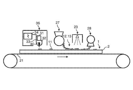
Figure la shows a single pass printer 35 comprising five digital print heads
30a-e,
which are connected with ink pipes 32 to ink containers 31 that are filled
with ink of
different colours. The print heads are connected with digital data cables 33
to a digital
control unit 34 that controls the application of the ink drops and the speed
of the
conveyor 21 that displaces the panel under the print heads with high precision
in
order to guarantee a high quality image comprising several colours. Figure lb
shows
a wood grain print P provided on a panel surface 2. The surface of a floor
panel is
often embossed with a standard structure 17 that is the same for several basic
decors
as shown in figure 1 c. Advanced floors use an embossing 17 that is in
register with
the printed pattern P as shown in figure id.
A normal width of an industrial print head is about 6 cm and any lengths may
be
printed. Wide areas of 1-2 m may be printed with digital printers comprising
several
rows of print heads aligned side by side.
Number of dots per inch or DPI is used to define the resolution and the
printing
quality of a digital printer. 300 DPI is generally sufficient to, for example,
print wood
grains structures of the same quality presently used in conventional laminate
floorings. Industrial printers can print patterns with a resolution of 300 ¨
600 DPI and
even more and with a speed exceeding 60 m/min.
The print may be a "full print." This means that the visible printed decor is
mainly
created by the ink pixels applied on the surface. The colour of a powder layer
or a
base colour of a paper has in such an embodiment, in general a limited effect
on the
visible pattern or decor.
The print may also be a "part print". The colour of another underlying layer
is one of
the colours that are visual in the final decor. The area covered by printed
pixels and
CA 02878375 2015-01-05
WO 2014/017972 PCT/SE2013/050898
6
the amount of ink that is used may be reduced and cost savings may be obtained
due
to lower use of ink and increased printing capacity compared to a full print
design.
However a part print is not as flexible as a full print since the base colours
are more
difficult to change than when a full print is used
The print may be based on the CMYK colour principle. This is a 4-colour setup
comprising cyan, magenta, yellow and black. Mixing these together will give a
colour
space/gamut, which is relatively small. To increase specific colour or the
total gamut
spot colours may be added. A spot colour may be any colour. The colours are
mixed
and controlled by a combination of software and hardware (print engine/print
heads).
New technology has been developed by Valinge Innovation AB that makes it
possible
to inject a digital print into a powder layer. This new type of "Digital
Injection Print"
or DIP is obtained due to the fact that printing is made into a powder that is
cured
after printing. The print is embedded into the cured layer and is not applied
on a layer
as when conventional printing methods are used. The print may be positioned in
several dimensions horizontally and vertically in different depths. This may
be used
to create 3D effects when transparent fibres are used and to increase the wear
resistance. No protective layers are needed that disturb the original design.
The DIP method may be used in all powder based materials, which may be cured
after printing. However, the DIP method is especially suitable to be used when
the
powder comprises a mix of wood fibres, small hard wear resistant particles and
a
melamine formaldehyde resin. The surface layer may also comprise thermoplastic
material, for example, vinyl particles, which are applied in powder form on a
substrate. This allows that the print may be injected in the vinyl powder
particles. An
improved design and increased wear resistance may be reached even in such
materials.
A suitable printer head has to be used in order to obtain a high printing
quality and
speed in powder based layers and other layers as described above. A printer
head has
several small nozzles that can shoot droplets of inks in a controlled way
(Drop On
Demand ¨ DOD). The size of each droplet may vary, dependant on ink type and
head
type, between normally 1-100 picolitres. It is possible to design print heads
that may
fire bigger drops up to 200 picolitres more. Some printer heads can shoot
different
CA 02878375 2015-01-05
WO 2014/017972 PCT/SE2013/050898
7
droplet sizes and they are able to print a greyscale. Other heads can only
shoot one
fixed droplet size.
Different technologies may be used to shoot the drops out of the nozzle.
Thermal printer head technology use print cartridges with a series of tiny
chambers
each containing a heater, all of which are constructed by photolithography. To
eject a
droplet from each chamber, a pulse of current is passed through the heating
element
causing a rapid vaporisation of the ink in the chamber to form a bubble, which
causes
a large pressure increase, propelling a droplet of ink out through the nozzle
to the
substrate. Most consumer inkjet printers, from companies including Canon,
Hewlett-
Packard, and Lexmark use thermal printer heads.
Most commercial and industrial inkjet printer heads and some consumer printers
such
as those produced by Epson, use the piezoelectric printer head technology. A
piezoelectric material in an ink-filled chamber behind each nozzle is used
instead of a
heating element. When a voltage is applied, the piezoelectric material changes
shape,
which generates a pressure pulse in the fluid forcing a droplet of ink from
the nozzle.
Piezoelectric (also called Piezo) inkjet allows a wider variety of inks than
thermal
inkjet, as there is no requirement for a volatile component, and no issue with
kogation. A lot of ink types may be used such as dye inks, solvent based inks,
latex
inks or UV curable inks.
Pigment based inks are generally individually mixed together by using colour
pigments and several chemicals. A pigment is a very fine powder of solid
colorant
particles that are suspended or dispersed throughout a liquid carrier.
Pigments used in
digital ink have an average particle size of about 0.1 micron. The common size
of the
nozzles are about 20 microns which meant that the pigment particle have enough
space to pass through the nozzle channels in the print head. The nozzles may
still be
blocked by the ink itself and pigments that form clusters of particles. A high
quality
pigment ink should keep the pigment suspended in the carrier fluid for a long
period
of time. This is difficult particularly at the low viscosities that are
required for a good
functioning of the print heads. Pigments have a natural tendency to settle out
and fall
down in the liquid carrier. In high quality pigment ink, no settling out of
the pigment
should normally occur.
CA 02878375 2015-01-05
WO 2014/017972 PCT/SE2013/050898
8
Water based inks comprising colour pigments are especially suitable and may
provide
a high quality printing method in many different materials. Pigment inks are
generally
more light fast and more fade resistant than dye-based inks.
The pigments do not stick to a surface. They are similar to sand particles and
may be
easily removed from most dry surfaces. The water based carrier fluid is
therefore
generally mixed with small amounts of several other additives to provide
special ink
and print properties, such as binders that provide the adhesion of the
pigments to a
surface, dot gain, pH level, drop formation, corrosion of the print head, fade
resistance etc.
Colour pigments as such are rather cost competitive but the production of
pigment
based inks and other inks for digital printers is very complicated and
expensive and
this results in a very high cost for the ink that normally may be in the
region of about
100 EUR/litre. About 100 m2 of flooring may be printed with one litre if a
full high
quality print is applied and this gives a cost of 1 EUR/m2. The costs for a
conventional printed floor surfaces where printing cylinders are used are only
10 A) of
the cost for digitally printed floor surfaces.
Digital ink jet printers use a non-contact method to apply the ink on a
surface. Laser
printing however is based on a contact method where a laser beam projects an
image
on an electrically charged rotating drum. Dry ink particles, generally called
toner, are
then electrostatically picked up by the drum's charged areas. The ink
comprises fine
particles of dry plastic powder mixed with carbon black or colouring agents.
The
thermosetting plastic material acts as a binder. The drum prints the image on
a paper
by direct contact and heat, which fuses the ink to the paper by bonding the
plastic
powder to the paper. Colour laser printers use the CMYK principle with
coloured dry
ink, typically cyan, magenta, yellow, and black that are mixed in order to
provide a
high quality coloured image.
The laser technology with the impact method is not used for printing of a flat
panel
surfaces such as a floor panel surfaces.
The above description of various known aspects is the applicants'
characterization of
such, and is not an admission that any of the above description is prior art.
Several of
CA 02878375 2015-01-05
WO 2014/017972 PCT/SE2013/050898
9
the technologies described above are known and used individually but not in
all
combinations and ways as described above.
As summary it may be mentioned that digital printing is a very flexible method
but it
cannot be fully utilized due to the high cost for the ink. The costs are
primarily caused
by the need to mill down the colour pigments to well-defined very small
particles and
to disperse the particles throughout the carrier fluid. It would be a major
advantage if
digital images may be created with ink that does not contain colour pigments
or
colour substances.
The digital application technology is only used to obtain advantages related
to the
1 0 possibility to create a high-resolution image in a flexible way.
However, the other
aspects of the technology, mainly related to the possibility to apply a liquid
substance
very precisely with a non-impact method, have not been fully utilized or
developed.
It is known that powder applied on a liquid substance could be used to create
raised
portions or an image on mainly a paper substrate and that the liquid substance
may be
applied digitally by ink jet.
US 3,083,116 describes raised printing powder and a raised printing process
comprising dusting a powdered resin upon a newly printed sheet, removing
therefrom
the excess powder which do not adhere to the wet ink, and applying heat to the
powder retained on the sheet to fuse it so that particles thereof will flow
together and
adhere to the sheet. The powder may comprise a phenolic resin.
US 3,446,184 describes a method to form a sticky image copy. Toner powder is
applied on a liquid forming and a portion of the powder is retained by the
liquid
coating, forming a visible image. Loose powder is removed and the sheet passes
a
heating unit where the retained powder is fused to form a permanent image
US 4,312,268 describes a method by which a water-based ink is applied
digitally to a
continuous web and fusible single colour powder material is applied to the web
and
on the ink. Some of the powder material is bonded to the liquid, and non-
bonded
powder material is removed from the web prior to heating of the web to dry the
liquid
and to fuse the powder material to the web by melting the powder. It is
mentioned
CA 02878375 2015-01-05
WO 2014/017972 PCT/SE2013/050898
that the powder material may have a particle size in the range of 5 to 1000
microns
and may have a melting point or fusing point in the range of 50 to 300 degrees
Centigrade. The powder material may be produced by dissolving or dispersing,
respectively, a dye or a pigment in a resin or resin foi ___________
inulation, followed by grinding,
5 spray chilling or the like to reduce the material to a fine powder. The
powder material
may provide abrasion resistant qualities to the ink that may contain phenolic
resin.
The liquid material, which is applied through the jets, may be clear and
colourless
water.
US 6,387,457 describes a method of printing using dry pigments. A binder
material is
10 applied to a surface of a substrate uniformly or in a pattern. Dry
pigment is applied to
the binder material in a pattern or uniformly. The dry pigment material
comprises
flakes of non-metallic material having a particle size less than about 100
micron. The
flakes are aligned in a direction parallel with the surface of the substrate.
EP 0 403 264 A2 describes a transfer method to form a multi-colour image on a
drum
that transfers the image to a paper. A fluid digital latent image is
subsequently
developed at a development station where coloured powder is applied to the
fluent
latent image and fixed to produce a visible and permanent image. Several
digital print
heads may be used that print with dyeless fluids comprising a mixture of water
with
polyhydric alcohols and their sub-sets of ethylene glycol, glycerol,
diethylene glycol
and polyethylene glycol. A powder toner is applied across the surface of the
paper
and a voltage is applied during this development. The voltage is then reversed
to
remove the toner from the background areas. Fixing is achieved by means of
conventional copier fusing methods.
EP 0 657 309 Al describes a multicolour transfer method utilizing a transfer
paper
carrying a pattern formed by ink jet and powder similar to the above described
methods. The transfer method is intended for decorating ceramics.
WO 2011/107610 describes a method to create an elevation or an embossing on a
floor panel in order to avoid the use of expensive press plates. The method is
the
same as the known methods to create a raised print. It describes a method to
produce
CA 02878375 2015-01-05
WO 2014/017972 PCT/SE2013/050898
11
a floorboard by printing a curable substance for creating an elevation on the
panel.
The elevation may be applied on a basic decorative pattern that is directly
printed or
laminated on the panel. The curable substance may comprise wear resistant
particles.
The curable substance may be digitally printed on the panel by first printing
a liquid
in a pre-defined pattern and then providing an intermediate substance that may
comprise a powder. The curable substance may be cured by UV radiation or may
be a
varnish.
The known methods are not suitable for creating a high quality multi-colour
image on
a building panel, and especially not on a floor panel where UV resistant
pigments
must be used and where the image must be incorporated into a wear resistant
surface.
It is not known that the known principles may be used to create an image on a
flooring surface that is pressed and especially not how the principles should
be
adapted for printing of floor surfaces similar to laminate and Wood Fibre
Floors
(WFF) where the powder, the ink and the application methods must be adapted to
the
specific resins, materials and pressing parameters which are needed to form a
wear,
impact and stain resistant high quality multi-colour surface in a cost
efficient way.
Objects and Summary
The objective of at least certain embodiments of the invention is to provide a
method
and equipment to produce a digitally printed building panel, preferably a
floor panel,
that may be produced in a more cost efficient way without ink that comprises a
colour
substance, for example, without colour pigments that are complicated to handle
in a
digital printing head.
The above objectives are exemplary, and the embodiments of the invention may
accomplish different or additional embodiments.
A first aspect of the invention is a method of forming a digitally printed
image with
colour pigments on a surface of a building panel, comprising the steps of:
= scattering dry colour pigments on the surface,
= bonding a part of the dry colour pigments to the surface, and
= removing the non-bonded dry colour pigments from the surface such that a
digitally created image is formed by the bonded colour pigments.
CA 02878375 2015-01-05
WO 2014/017972 PCT/SE2013/050898
12
According to a first principle of the first aspect, a pattern or image may be
formed
digitally by a digital coating head that only applies a binder on a surface.
The
pigments are scattered randomly by a second device over the pattern. The
binder
connects some pigments to form the same pattern as the binder while other non-
bonded pigments are removed.
This two-step process, where the pigments and a liquid binder are applied
separately,
may provide an image with a comparable quality as conventional digital
printing
technology, for example comparable to at least 300 DPI.
According to a second principle of the first aspect the pigments may be
scattered on a
surface in a first step and a digital coating head that only applies a binder
on the
scattered mix thereafter forms a pattern or image digitally. The digitally
applied
binder may comprise water that melts for example melamine formaldehyde
particles
that may be mixed with pigments, preferably substantially homogenously mixed
with
the pigments. The binder connects some pigments that form the same pattern as
the
binder while other non-bonded pigments are removed.
According to a third principle of the first aspect the pigments may be
scattered on a
surface in a first step and a binder pattern or image is thereafter formed
digitally by a
laser beam that bonds some pigments to the surface by melting or curing a
binder that
may be mixed with the pigments or included in the surface under the pigments.
A
digitally created print is obtained when the non-bonded pigments are removed.
The dry colour pigments may be bonded to a binder on the surface of the
building
panel. The binder may be separately applied on the surface of the building
panel.
The dry colour pigments may be mixed with a binder.
The binder may be a powder, preferably a dry powder, or a liquid substance.
The binder may comprise a thermosetting or a thermoplastic resin. The surface
of the
building panel may comprise a thermosetting resin, preferably melamine
formaldehyde resin.
The surface may be a paper layer, a foil, a wood or wood-based layer, or a
powder
layer. The powder layer may comprise a mix comprising lignocellulosic or
cellulosic
particles, a binder and optionally wear resistant particles, for example,
aluminium
CA 02878375 2015-01-05
WO 2014/017972 PCT/SE2013/050898
13
oxide. The binder is preferably a thermosetting binder such as melamine
formaldehyde resin.
The building panel may have a surface of a resin impregnated paper,
thermoplastic
film or foil, a powder layer comprising lignocellulosic or cellulosic
particles and a
binder. The building panel may be formed by applying heat and pressure.
The building panel may be a floor panel. The surface may be a part of a floor
panel.
The floor panel may comprise a mechanical locking system for vertical and
horizontal
locking.
The building panel may be a wall panel or a furniture component. The surface
may be
a part of a wall panel or a furniture component.
The pigments may be removed by an airstream.
The step of bonding said part of the dry colour pigments to the surface may
comprise
applying a liquid substance by a digital coating head. The liquid substance
may be
applied on the surface before the dry colour pigments are applied on the
surface, or
may be applied on the surface after the dry colour pigments have been applied
on the
surface.
The liquid substance may be water based.
The liquid substance may be exposed to UV light.
The liquid substance may be water based UV curable polyurethane.
The liquid substance may comprise a binder such as a thermosetting or a
thermoplastic binder.
The liquid substance may be applied with a Piezo ink head.
The step of bonding said part of the dry colour pigments to the surface may
comprise
applying a laser beam to bond the dry colour pigments to the surface.
The method may further comprise applying heat and pressure to the surface of
the
building panel. The surface of the building panel may be pressed after the
digitally
created image has been formed by the bonded colour pigments. Final bonding of
the
dry colour pigments to the surface of the building panel may occur by applying
heat
and pressure to the surface of the building panel. For example, the binder
bonding the
= = 81785047
14
dry colour pigments to the surface of the building panel may be cured by
applying heat and
pressure to the surface of the building panel. The binder, for example a
thermosetting resin such as
melamine formaldehyde resin, bonding the dry colour pigments to the surface of
the building
panel may be cured simultaneously as the binder, for example a thermosetting
resin such as
melamine formaldehyde resin, of the surface of the building panel. The curing
may occur by
applying heat and pressure to the surface of the building panel.
Another aspect of the invention is to provide equipment to form a digital
image on a building panel,
wherein the equipment comprises a digital coating head, a powder scattering
unit, and a powder
removal system. The digital coating head is configured to apply a liquid
substance on a surface of
the building panel or on a layer of powder comprising colour pigments and/or
binder on a surface of
the building panel. The powder scattering unit is configured to apply a powder
layer comprising
colour pigments on the surface of the building panel. The liquid substance is
configured to bond a
part of the powder to the surface of the building panel, and the powder
removal unit is configured to
remove the non-bonded powder from the surface of the building panel. A digital
image is thereby
formed by the bonded colour pigments.
The powder may comprise a thermosetting resin.
The liquid substance may be water based. The liquid substance may be exposed
to UV light.
A surface of the building panel comprises a thermosetting resin, preferably
melamine
formaldehyde resin.
The equipment may further comprise a pressing unit adapted to apply heat and
pressure to the
surface of the building panel. The surface of the building panel may be
pressed after the digital
image has been formed by the bonded colour pigments.
According to another aspect of the present invention, there is provided a
method of forming a
digitally printed image with colour pigments on a surface of a building panel,
comprising the steps
of: scattering dry colour pigments on the surface, bonding a part of the dry
colour pigments to the
surface, removing the non-bonded dry colour pigments from the surface such
that the digitally
printed image is formed by the bonded colour pigments, and applying heat and
pressure to the
surface of the building panel, wherein the step of bonding said part of the
dry colour pigments to
the surface comprises applying a liquid substance by a digital coating head.
CA 2878375 2020-01-31
81785047
14a
According to another aspect of the present invention, there is provided a
method of forming a
digitally printed image with colour pigments on a surface of a building panel,
comprising the steps
of: scattering dry colour pigments on the surface, bonding a part of the dry
colour pigments to the
surface, and removing the non-bonded dry colour pigments from the surface such
that the digitally
printed image is formed by the bonded colour pigments, wherein the building
panel comprises a
mechanical locking system for vertical and horizontal locking.
According to another aspect of the present invention, there is provided a
method of forming a
digitally printed image with colour pigments on a surface of a building panel,
comprising the steps
of: scattering dry colour pigments on the surface, bonding a part of the dry
colour pigments to the
surface, and removing the non-bonded dry colour pigments from the surface such
that the digitally
printed image is formed by the bonded colour pigments, wherein the non-bonded
dry colour
pigments are removed by an airstream.
According to another aspect of the present invention, there is provided a
method of forming a
digitally printed image with colour pigments on a surface of a building panel,
comprising the steps
of: scattering dry colour pigments on the surface, bonding a part of the dry
colour pigments to the
surface, and removing the non-bonded dry colour pigments from the surface such
that the digitally
printed image is formed by the bonded colour pigments, wherein the step of
bonding said part of
the dry colour pigments to the surface comprises applying a laser beam.
According to another aspect of the present invention, there is provided a
method of forming a
digitally printed image with colour pigments on a surface of a building panel,
comprising the steps
of: scattering dry colour pigments on the surface; bonding a part of the dry
colour pigments to the
surface; and removing the non-bonded dry colour pigments from the surface such
that the digitally
printed image is formed by the bonded colour pigments, wherein the dry colour
pigments are
bonded to a binder, the binder being separately applied on the surface of the
building panel,
wherein the binder is a liquid substance, and wherein the method further
comprises applying heat
and pressure to the surface of the building panel.
According to another aspect of the present invention, there is provided
equipment to provide a
digital image on a building panel, wherein the equipment comprises a digital
coating head, a
powder scattering unit, and a powder removal unit, wherein: the digital
coating head is configured
to apply a liquid substance, and the powder scattering unit is configured to
apply a powder on the
Date Recue/Date Received 2020-09-04
81785047
14b
building panel, said liquid substance being configured to bond a part of the
powder to the building
panel, and the powder removal unit is configured to remove non-bonded powder
from the building
panel.
The production method and equipment according to embodiments of the invention
make it
possible to produce very advanced decorative patterns in a flexible and very
cost efficient way
since the digital equipment is only used to create a pattern with a binder
that does not have any
colour pigments.
Embodiments and details of various aspects may be combined with embodiments
and details of
the other aspects. Mixing colour pigments in the liquid binder is not
Date Recue/Date Received 2020-09-04
CA 02878375 2015-01-05
WO 2014/017972 PCT/SE2013/050898
excluded and this may be used to, for example, apply smaller amounts of
pigments
with the digital coating head that may be needed for a specific colour
combination.
Brief Description of the Drawings
The invention will in the following be described in connection to exemplary
5 embodiments and in greater detail with reference to the appended
exemplary
drawings, wherein,
Figs la-d illustrate know methods to produce a printed and embossed
surface;
Figs 2a-d illustrate a first aspect of the invention;
Figs 3a-d illustrate a second aspect of the invention;
1 0 Figs 4a-d illustrate a third aspect of the invention;
Figs 5a-h illustrate digital application of pigments according to the
first aspect
of the invention;
Figs 6a-c illustrate embodiments of the invention.
Detailed Description of Embodiments
15 Figures 2a-2d show an embodiment of the invention, which is based on a
first
principle where a binder pattern BP or image is formed digitally by a digital
coating
head that applies a binder 11 in the form of a liquid substance. A digital
print head or
digital ink head that is mainly used to apply a liquid substance without any
colorants,
and which is not intended to print a coloured image is hereafter referred to
as a
"digital coating head". Pigments 12 are scattered randomly by a second device
over
the binder pattern BP. The binder connects some pigments to form the same
pattern
as the binder while other non-bonded pigments are removed.
This two-step process, where the pigments and a liquid binder are applied
separately,
may provide an image with the same quality as conventional digital printing
technology. The method is particularly suitable in applications where
considerable
quantities of pigments have to be applied on a large flat panel 1 in order to
foun an
advanced large image or decorative pattern. Contrary to known methods, the
digital
coating head is typically not used to apply any type of conventional ink with
colour
CA 02878375 2015-01-05
WO 2014/017972 PCT/SE2013/050898
16
pigments. This is a major advantage since no expensive inks comprising pigment
dispersions have to be handled by the digital coating head.
Figure 2a shows that a binder pattern BP is formed on a surface 2 of a
building panell
by a digital coating head 30 as shown in figure 2d. The surface 2 may for
example be
a paper layer, a stabilized powder layer, a foil or a base colour applied on a
material
preferably o a wood or plastic based core material. The binder 11 is in this
preferred
embodiment water based and comprises preferably mainly water, such as at least
50
% water. The binder 11 may further comprise additives such as release agents,
surface tension agents, wetting agents, viscosity increasing agents etc. A
pigment
layer 12 is applied, for example, by scattering as dry powder over the wet
binder
pattern BP as shown in figure 2b The pigment layer may comprise, for example,
melamine formaldehyde powder particles that melt when they are in contact with
the
water-based pattern BP. The dry pigments and melamine formaldehyde powder that
do not contact the water-based pattern BP are is removed by, for example, an
air
stream and the remaining colour pigments 12 form a print P as shown in figure
2c,
which is essentially identical to the binder pattern BP.
The print P may be dried and stabilized by, for example, exposure to IR or UV
lights
that heat up the wet melamine formaldehyde resin and bond the colour pigments
to
the surface 2 by drying the wet melamine formaldehyde resin. A second bonded
pattern may be coated on the surface 2 and a second layer of pigments and
melamine
formaldehyde powder may be applied on the surface and over and/or adjacent to
the
first print. An advanced decor may be created with several colours.
The binder in this embodiment may comprise wet melamine formaldehyde and may
be applied in two steps, first as a liquid substance, such as water, from the
digital
coating head 30, and second as powder from a scattering unit 27. The powder
may be
mixed with the dry colour pigments. This simplifies the function of the
digital coating
head that only has to apply water drops without any, or with limited amounts
of,
binders and colour pigments.
The binder may be included in dry form in the powder and activated by the
liquid
substance applied by the coating head as described above or it may only be
included
in the liquid substance applied by the digital coating head.
CA 02878375 2015-01-05
WO 2014/017972 PCT/SE2013/050898
17
This method wherein the liquid substance and the powder are applied directly
on a
panel is suitable to form a digital image on a building panel. A method
comprising the
following steps is especially suitable for forming an image on a floor surface
having
high impact and wear resistance. A liquid substance compatible with
thermosetting
resins is applied and the substance must have specific chemical properties
such that
no defects are caused during curing of the thermosetting resins. This may be
accomplished with a liquid substance that for example comprises water and/or
glycols. The substance should be applied on a surface of a building panel in
order to
eliminate problems related to positioning of the print on the panel.
Thermosetting
resins such a melamine formaldehyde resins are preferably included in a
surface layer
of a panel and/or in the powder applied on the panel and they may react with
the
liquid substance and bond the powder to the panel surface such that non-bonded
powder may be removed. The powder comprises preferably UV stable colour
pigments. The advantages are that such combination of materials may be pressed
and
cured with high pressure, exceeding 40 bars, and heated to a temperature
exceeding
160 degrees Celsius The surface and the digitally formed image may be cured to
a
hard wear resistant surface without so called bleeding of the pigments during
the
pressing and heating step and the pigments may be incorporated into the cured
surface such that they may create a UV stable wear resistant image similar to
the
images of conventional laminate floors.
A wide variety of thermosetting and thermoplastic materials may be used as
particles
in the scattered powder or as dispersions or liquid substances in the binder
applied by
the digital coating head. The majority of such materials may be produced in
dry
powder form or as liquid dispersions.
As an alternative to thermosetting materials, such as melamine formaldehyde,
or to
thermoplastic materials, such as, for example, PVC powder, UV curable
polyurethane
may, for example, be used in powder form or as dispersion.
UV curable polyurethane substance with a viscosity that is adapted to the
digital
coating head 30 may be used. Water-based polyurethane dispersions are
preferred as
a liquid substance in the digital coating head since they do not cure until
they are
exposed to UV light. Polyurethane dispersions are fully reacted polyurethane/
polyureas of small and discrete polymer particles and such particles may be
produced
CA 02878375 2015-01-05
WO 2014/017972 PCT/SE2013/050898
18
with a size of about 0.01-5.0 microns and may therefore be handled in a
digital print
head or other similar heads. They may have 20 -70% solid content. Polyurethane
dispersions may be blended with, for example, acrylic emulsions and other
emulsions
in order to reduce costs.
The digital coating head 30 that preferably is a Piezo head has preferably a
capacity
to fire drops with a drop size of about 1 - 200 picolitres or more. The drop
size may
be varied and this may be used to vary the intensity of a colour and to create
a grey
scale with the same basic colour.
Water based adhesives may also be used such as soluble adhesives or water
dispersed
1 0 adhesives.
Other UV curable materials such as acrylates of epoxy, urethane, polyester,
polyether,
amine modified polyether acrylic and miscellaneous acrylate oligomers may be
used
in powder for or as dispersions.
Figure 2d shows one "binder printing" station of a binder printing equipment
that
may be used to create a digital print with the digital "binder print" method.
A digital
coating head 30 that may be a Piezo head applies a binder pattern BP. Several
coating
heads 30 may be positioned side by side in order to cover the width of the
surface that
is printed. The binder pattern is created digitally in the same way as in
conventional
digital printing. The colours are separated and each coating unit 36 applies
mainly the
same substance that is used to bond one specific colour in each coating step.
The
digital coating head is connected with a feeding pipe 32 to a container 31
that
comprises a binder or a one component of a binder, preferably a water based
substance, which in this embodiment may be mainly distilled or deionized
water. The
digital coating heads are connected with digital data cables 33 to a digital
control unit
34 that controls the application of the drops, the speed of the conveyor 21,
the
function of a powder application unit and all other equipment that is used to
bond and
remove pigments.
The water drops that serve as a binder 11 should be wet until they pass a
scattering
station 27 that applies a powder mix that in this preferred embodiment
comprises
colour pigments 12 and melamine formaldehyde powder 13. The melamine
formaldehyde particles in the powder mix that are in contact with the wet
water based
CA 02878375 2015-01-05
WO 2014/017972 PCT/SE2013/050898
19
binder pattern BP melts and the water/melamine formaldehyde solution acts as a
binder that connects a part of the pigment/melamine formaldehyde mix to the
surface
2 of the panel 1. When the powder mix is displaced under a preferably hot UV
curing
oven 23 with ultra violet light, which is located preferably after the digital
coating
unit 36 in the feeding direction, a practically instant bonding or curing
within a few
seconds may take place.
A powder removal system 28 that in this embodiment is based on an air stream
and
vacuum removes pigments and melamine formaldehyde particles that are not
bonded
by the binder pattern BP and a perfect colour print P is provided. This
production step
may be repeated and another colour may be applied by a second scattering unit
27
that comprises another colour. The removed dried pigments and melamine
formaldehyde particles may pass through a sieve or a filter and they may be
recycled
and reused again several times.
Melamine formaldehyde or other binders may also be included in the surface
layer 2
as a dry layer when, for example, a melamine formaldehyde impregnated paper
layer
or a stabilized powder layer is used as a basic surface. The water based
bonding
pattern will melt a part of this melamine formaldehyde layer and only pigments
may
be applied as powder by the scattering unit 27 and recycled. This method may
also be
used when a complete binder substance is included in the liquid substance
applied by
the digital coating head.
The powder mix may, in addition to pigments and melamine formaldehyde
particles
,also comprise wear resistant particles such as small aluminium oxide
particles and
fibres, preferably wood fibres that preferably comprise bleached transparent
or semi-
transparent fibres. Such a mix may be used to create a solid print with
pigments that
are positioned vertically above each other with binders and wear resistant
particles
above and below the pigments. A water-based substance without any pigments may
penetrate deeper into the powder mix than pigments applied as dispersion in a
conventional digital printing and a very wear resistant print may be obtained.
Several layers of prints may be position above each other and this may be used
to
increase the wear resistance further and to create 3D decorative effects.
CA 02878375 2015-01-05
WO 2014/017972 PCT/SE2013/050898
Static electricity may be used to apply and/or to remove the non-bonded powder
particles. Airstreams and vacuum that blows away and/or sucks up particles may
be
combined with brushes. In general all dry and wet methods that are used to
remove
dust may be used separately or in various combinations to remove the pigments
and
5 the non-bonded parts of the scattered powder mix. However, dry and non-
impact
methods are preferred.
A controlled complete or partial removal of the non-bonded pigments is
essential for
a high quality print with a pre-defined decorative image. Advanced removal
systems
may also be used that only removes the colour pigments while the essential
part of the
10 transparent melamine formaldehyde powder particles may remain on the
surface. This
may be accomplished by for example a two-step scattering where a first layer
comprises only melamine formaldehyde particles that are connected to the
surface
prior to the application of the binder, sprayed with water and dried with IR,
hot air,
UV and similar methods. This separate melamine formaldehyde layer may in some
15 applications replace, for example, pre-impregnated paper and only non-
impregnated
paper with or without a base colour may be used as a surface layer 2.
The moisture content of the surface layer should be accurately controlled in
order to
facilitate the removal of the non-bonded powder particles. Moisture content
below
6% is preferred. The surface layer 2 may be dried by, for example, IR or UV
lamps or
20 hot air prior to the application of the pigments. Water and special
chemical, such as
release agents, may be applied in order to seal the surface 2 or the upper
part of the
bonded colour pigments in order to create a sealing or a release layer that
may
prevent colour pigments to stick to specific parts of the surface layer where
no binder
is applied.
The print may be covered with transparent protective layers of, for example, a
paper
based or powder based overlay comprising aluminium oxide and melamine
formaldehyde resins or a UV curing coating that may be applied by rollers or
digitally
with, for example, Piezo coating heads.
Figures 3a ¨ 3d show an embodiment of the invention, which is based on a
second
principle where the pigments 12 in a first step are scattered on a surface 2
and a
pattern or image is thereafter formed digitally by a digital coating head that
only
CA 02878375 2015-01-05
WO 2014/017972 PCT/SE2013/050898
21
applies a binder pattern BP on the scattered mix. The digitally applied binder
may
comprise water that melts for example melamine formaldehyde particles 13 mixed
with pigments 12 or applied under the pigments. The binder connects some
pigments
to form the same pattern as the binder pattern BP while other non-bonded
pigments
are removed. Figure 3a shows a substantially homogenous mix of melamine
formaldehyde powder 13 and pigments 12 scattered on a surface 2. Figure 3b
shows a
digitally applied binder pattern BP applied on the mix. Figure 3c shows that
all non-
bonded pigments and in this embodiment also melamine formaldehyde particles 13
have been removed. Figure 3d shows a binder printing station comprising a
scattering
unit 27, a digital coating unit 36, a UV oven 23 and a powder removal system
based
28 on an air stream and vacuum.
The first and the second principles may be combined. A binder pattern may be
applied prior and after the application of the pigment mix and this may be
used to
create a solid print with a larger vertical extension and higher wear
resistance.
Figures 4a ¨ 4c show an embodiment of the invention, which is based on a third
principle where the pigments 12 in a first step are scattered on a surface 2
and a
binder pattern BP or image is thereafter formed digitally by a laser beam 29
that melts
or cures a binder that may be mixed with the pigments 12 or included in the
surface 2.
A digitally created print P is obtained when the non-bonded pigments are
removed.
Figure 4d shows a binder printing station comprising a scattering unit 27, a
laser 29,
and a powder removal system 28 based on an air stream and vacuum. The laser
may
be replaced with heating lamps that may be used to create images that comprise
rather
large areas of the same colour as in some stone designs. Even a conventional
laser
system based on the above described impact method may be used to apply an
digital
print partly or completely on a floor panel or in combination with the above
described
binder printing methods.
All the above-described principles may be partly or completely combined and a
production line may comprise several digital binder printing station according
to the
first, second or third principles.
Figures 5a ¨ 5h show application of two different colours according to the
first
principle. A first binder 1 1 a that in this embodiment is essentially water
is applied by
CA 02878375 2015-01-05
WO 2014/017972 PCT/SE2013/050898
22
a digital Piezo head on a surface 2 that may be a stabilized powder layer or a
paper as
shown in figure 5a. A first powder layer comprising colour pigments 12a and
melamine formaldehyde particles 13a is applied on the surface 2 and on the
binder
11 a. Melamine formaldehyde particles 13a that are in contact with the wet
water
drops will melt. A first UV oven 23a dries the wet melamine formaldehyde and
bonds
the pigments to the surface as shown in figure Sc and the non-bonded melamine
formaldehyde and pigment particles are removed such that a pigment image 12a
that
corresponds to the applied binder lla is obtained. Figures 5e ¨ 5h show that
the same
application may be repeated with another pigment colour 12b mixed with
melamine
formaldehyde particles 13b and a new binder 1 lb such that a two colour image
is
obtained with two types of colour pigments 12a, 12b as shown in figure 5h.
Figure 6a shows an embodiment where the digital binder printing equipment
comprising a digital coating unit 36, a scattering unit 27, UV curing unit 23,
and a
powder removal vacuum system 28, is combined with conventional ink jet printer
35.
The binder printing method may use this combination to create the major part
of a
digital image while some parts of the final print may be created by the ink
jet printer.
This may reduce the ink cost considerably since for example the cost effective
binder
printing method, where no pigments have to be handled by the digital coating
head,
may apply for example 90% of the pigments which are needed to create a fully
printed decor or pattern.
Figure 6b shows a binder printing equipment where pigments 12 and melamine
formaldehyde powder 13 are applied by a scattering unit 27 comprising
preferably an
embossed roller 22 and an oscillating brush 42. The non-bonded pigments and
melamine formaldehyde particles are removed by a powder removal system 28 that
recycles the mix 12, 13 into the scattering unit 27. A pigment/melamine
formaldehyde dust cloud may be created by airstreams and only the pigments and
melamine formaldehyde powder that come into contact with the wet binder 11
will be
bonded to the surface 2
Figure 6c shows that the method is especially suited to apply a digital binder
print on
a floor panel 1 with a paper based or powder based surface 2, a core 3, a
balancing
layer 4, and with a mechanical locking system comprising a strip 6, with a
locking
element 8 in one edge that cooperates with a locking groove 14 in an adjacent
edge of
CA 02878375 2015-01-05
WO 2014/017972 PCT/SE2013/050898
23
another panel for horizontal locking of the adjacent edges and a tongue 10 in
one
edge that cooperated with a tongue groove 9 in another edge for vertical
locking of
the panels. Such floor panels have generally advanced wood or stone decors
that
require large amounts of different colour pigments and a decor that has to be
positioned accurately in relation to embossed stnictures and the panel edges
with the
mechanical locking system.
In all embodiments, the surface of the building panel may comprise a
thermosetting
resin, for example, melamine formaldehyde resin. The building panel may be
formed
by applying heat and pressure, preferably after the digitally created image is
formed
by the bonded colour pigments In one embodiment, the binder mixed with the dry
colour pigments is cured simultaneously as the binder in the surface of the
building
panel, preferably by applying heat and pressure.
All the above-described methods may be partly or completely combined.
EXAMPLE
A powder mix of 300 g/m2 comprising wood fibres, melamine formaldehyde
particles, brown colour pigments and aluminium oxide particles such as
corundum
was applied by scattering equipment on an 8 mm HDF core. The mix was sprayed
with deionized water and dried by an UV oven such that a hard stabilized
powder
based surface with a brown basic colour was obtained. The panel with the
stabilized
powder surface was put on a conveyer and displaced under a digital Piezo
coating
head that applied drops of water on the stabilized surface and that printed a
transparent wood grain pattern on the surface. The melamine formaldehyde under
the
transparent pattern melted when the digital coating Piezo head applied the
water
drops. Black pigments were in a second step scattered over the whole surface
and the
transparent pattern. The panel was thereafter displaced by a conveyor under an
UV
oven. The melamine formaldehyde in the transparent pattern was dried again and
the
pigments above the transparent pattern were bonded to the surface. The panel
was
thereafter displaced under a vacuum-sucking pipe where all non-bonded pigments
and
melamine formaldehyde particles were removed. A wood grain pattern comprising
a
brown base colour and a black wood grains structure was obtained. A protective
layer
comprising melamine formaldehyde and aluminium oxide particles was scattered
CA 02878375 2015-01-05
WO 2014/017972 PCT/SE2013/050898
24
over the entire surface. The layer was sprayed with water and dried under an
UV
oven. The panel with the print and the protective layer was thereafter pressed
during
20 seconds under a temperature of 170 degrees C in a 40 bars press and the
powder-
based surface with the grain structure and the protective layer was cured to a
hard
wear resistant surface with a high quality print