Note: Descriptions are shown in the official language in which they were submitted.
METHODS AND SYSTEMS RELATED TO
ESTABLISHING GEO-FENCE BOUNDARIES
BACKGROUND
100011 Governments, including state and federal governments, have
traditionally funded
public infrastructure projects from tax revenue derived from fuel taxes.
States may tax fuel
purchased not only by in-state drivers, but also by drivers that travel
through the state. With
the development and availability of hybrid and electric cars on the market,
governments will
need to consider new ways of deriving tax revenue to fund public
infrastructure. Therefore, any
invention which provides information related to calculating and collecting
transportation takes
would be useful.
SUMMARY OF THE INVENTION
10001A] In a broad aspect, the invention pertains to a method comprising
detecting, by way
of an on-board device coupled to a vehicle, that the vehicle is located within
a first political
boundary, and establishing a first geo-fence boundary for the vehicle
corresponding to the first
political boundary, the establishing responsive to detecting the vehicle being
within the first
political boundary. Data regarding the vehicle movement within the first geo-
fence boundary
is collected and the vehicle detecting that the vehicle has departed the first
geo-fence boundary.
At an operations center, a periodic transmission is received from an on-board
device, even when
there is no active data collection.
10001B1 In a further aspect, the invention provides a system comprising a
processor, and a
memory coupled to the processor. The memory stores a program that, when
executed by the
processor, causes the processor to detect that a vehicle is located within a
first political boundary
through an on-board vehicle coupled to the vehicle. A first geo-fence boundary
is established
for the vehicle corresponding to the first political boundary, the
establishing being responsive
1
CA 2878392 2018-03-19
to detecting that the vehicle is within the first political boundary. Data
regarding the vehicle
movement within the first geo-fence boundary is collected, and detects that
the vehicle has
departed the first geo-fence boundary through an on-board device coupled to
the vehicle. A
periodic transmission is sent, even when there is no active data collection.
BRIEF DESCRIPTION OF THE DRAWINGS
100021 For a detailed description of exemplary embodiments, reference will
now be made
to the accompanying drawings in which:
[0003] Figure 1 shows, in block diagram form, an overall architecture of a
system in
accordance with at least some embodiments;
100041 Figure 2 shows an example embodiment of establishing a geo-fence;
100051 Figure 3 shows an example embodiment of establishing a second geo-
fence;
[0006] Figure 4 shows, in block diagram form, a monitoring module in
accordance with
at least some embodiments;
[0007] Figure 5 shows, in block diagram form, an after-market system
connected to a
vehicle in accordance with at least some embodiments;
10008] Figure 6 shows a computer system in accordance with at least some
embodiments;
and
[0009] Figure 7 shows, in block flow diagram form, a method in accordance
with at least
some embodiments.
la
CA 2878392 2018-03-19
CA 02878392 2015-01-05
WO 2014/011445 PCT/US2013/049090
NOTATION AND NOMENCLATURE
[0010] Certain terms are used throughout the following description and claims
to
refer to particular system components. As one skilled in the art will
appreciate,
different companies may refer to a component and/or method by different names.
This document does not intended to distinguish between components and/or
methods that differ in name but not in function.
[0011] In the following discussion and in the claims, the terms "including"
and
"comprising" are used in an open-ended fashion, and thus should be interpreted
to
mean Including, but not limited to... ." Also, the term "couple" or "couples"
is
intended to mean either an indirect or direct connection. Thus, if a first
device
couples to a second device that connection may be through a direct connection
or
through an indirect connection via other devices and connections.
[0012] "Remote" shall mean one kilometer or more.
[0013] "Political Boundary" shall mean the geographic boundary of a political
entity
or legal jurisdiction.
DETAILED DESCRIPTION
[0014] The following discussion is directed to various embodiments of the
invention. Although one or more of these embodiments may be preferred, the
embodiments disclosed should not be interpreted, or otherwise used, as
limiting
the scope of the disclosure, including the claims. In addition, one skilled in
the art
will understand that the following description has broad application, and the
discussion of any embodiment is meant only to be exemplary of that embodiment,
and not intended to intimate that the scope of the disclosure, including the
claims,
is limited to that embodiment
0015] Various embodiments are directed to configuring and creating a geo-
fence boundary corresponding to the size and shape of a political boundary
once
a vehicle is detected as having crossed into the area defined by the political
boundary, as well as collecting data related to the movement of the vehicle
within
the geo-fence boundary. The specification first turns to an illustrative
system.
2
CA 02878392 2015-01-05
WO 2014/011445 PCT/US2013/049090
[0016] Figure 1 shows, in block diagram form, a system in accordance with at
least some embodiments. In particular, the system comprises an operations
center 100 communicatively coupled to a vehicle 120 by way of a wireless
network 112. The operations center 100 comprises a processor 102. In some
embodiments, the processor 102 may be a stand-alone computer system, or the
processor may comprise a plurality of computer systems communicatively coupled
and performing the functions of the operations center, the functions discussed
more thoroughly below. The processor 102 may couple to an administrative user
interface 104. The administrative user interface 104 may enable a system
administrator 114 to control or configure the operation of the system. In some
embodiments, the processor 102 may also couple to an owner user interface 106,
which likewise enables an owner of the vehicle to interact with the system.
[0017] The operations center 100 may further comprise a mapping module 110
coupled to the processor 102. In accordance with at least some embodiments,
the
mapping module 110 is a stand-alone computer system executing software to
perform a mapping function associated with the location of the vehicle 120 and
any geo-fence boundaries that may be established. In yet still other
embodiments,
the mapping module 110 may be a computer program or program package that
operates or executes on the processor 102.
[0018] In order to communicate with the vehicle 120, the operations center may
further comprise a network interface 108 communicatively coupled to the
processor 102. By way of the network interface, the processor 102, and any
programs executing thereon, may communicate with vehicle 120, such as by
wireless network 112. Wireless network 112 is illustrative of any suitable
communications network, such as a cellular network, a pager network, or other
mechanism for transmitting information between the operations center 100 and
the
vehicle 120.
[0019] In accordance with at least some embodiments, the operations
center 100 is remotely located from the vehicle 120. In some cases, the
3
CA 02878392 2015-01-05
WO 2014/011445 PCT/US2013/049090
operations center 100 and vehicle 120 may be located within the same city or
state. In other cases, the operations center 100 may be many hundreds or
thousands of miles from vehicle 120, and thus the illustrative wireless
network 112
may span several different types of communication networks.
[0020] Still referring to Figure 1, the system further comprises a vehicle 120
communicatively coupled to operations center 100 by way of the illustrative
wireless network 112. The vehicle 120 may comprise a computer system 126
communicatively coupled to a wireless network interface 122 and a monitoring
system 124. The wireless network interface 122 enables the computer
system 126 to communicate with operations center 100 by way of a wireless
transmission through the wireless network 112. The monitoring system 124 may
assist the computer system 126 and/or the operations center 100 in determining
when the vehicle 120 has crossed into, or departed, a geo-fence boundary, and
may also assist the computer system 126 and/or the operations center 100 in
collecting data regarding movement of the vehicle 120 within an established
geo-
fence boundary. Various techniques for detecting a vehicle is located within a
political boundary, as well as determining whether vehicle 120 has departed a
geo-fence boundary, will be discussed more thoroughly below.
[0021] The specification now turns to a high level description of detecting a
vehicle is located within a political boundary and automatically establishing
a geo-
fence boundary corresponding to the political boundary. In particular, Figure
2
shows vehicle 120 located within political boundary 202. In this example, the
political boundary 202 is the border of the state of Texas, but the political
boundary
may be any political boundary, such as another state, a city, a county, or a
country. Detecting that vehicle 120 is located within political boundary 202
may
take many forms, but for purposes of this portion of the disclosure, assume
that
the detection is by way of, at least in part, a device or devices in the
monitoring
system 124 coupled to the computer 126.
4
CA 02878392 2015-01-05
WO 2014/011445 PCT/US2013/049090
[0022] Referring still to Figure 2, responsive to detection that vehicle 120
has
crossed a political boundary 202, a geo-fence boundary 204 is automatically
established having the shape and size corresponding to the political
boundary 202. More particularly, a geo-fence boundary 204 is automatically
established which corresponds to the borders of the political boundary 202.
The
establishing is without, at the time the vehicle 120 crosses into the state,
any input
from an administrator, vehicle owner, or external agent. Note that in this
example,
the geo-fence boundary 204 is aligned with the border of the state of Texas;
however, the geo-fence boundary may be aligned with another political boundary
such as county boundaries, city boundaries, or national boundaries. While the
vehicle 120 resides within the political boundary 202, the system may collect
data
regarding vehicle movement (discussed more below), and may also detect when
the vehicle has departed the political boundary 202, as discussed with respect
to
Figure 3.
[0023] Figure 3 shows a graphical representation of vehicle 120 crossing from
first political boundary to a second political boundary. In particular, in the
example
of Figure 3 the vehicle 120 crossed from the political boundary 202 being the
state
of Texas into the political boundary 302 being the state of New Mexico. In the
example of Figure 3, the system determines that the vehicle 120 has crossed
from
the political boundary 202 into political boundary 302. Detecting vehicle 120
is
now located within the political boundary 302, in this example, a geo-fence
boundary 304 is automatically established having the shape and size
corresponding to the political boundary 302. Additionally, at this point, the
geo-
fence boundary 202 corresponding to the size and shape of the political
boundary
of the state of Texas is de-established. The establishing of the geo-fence
boundary 302 is without, at the time the vehicle 120 crosses into the state,
any
input from an administrator, vehicle owner, or external agent. Note that in
this
example the geo-fence boundary is aligned with the borders of the state of New
Mexico; again, however, the geo-fence boundary may be aligned with another
CA 02878392 2015-01-05
WO 2014/011445 PCT/US2013/049090
political boundary such as county boundaries, city boundaries, or national
boundaries. While the vehicle 120 resides within the political boundary 302,
the
system may again collect data regarding vehicle movement (discussed more
below), and may also detect when the vehicle has departed the political
boundary 302. The specification now turns to example embodiments of
establishing a geo-fence boundary.
[0024] ESTABLISHING THE GEO-FENCE
[0025] Operations Center Establishment of the Geo-Fence
[0026] In some cases, mapping module 110 of the remote operations center 100
may play a role in establishing the geo-fence when vehicle 120 crosses into a
political boundary. In particular, the mapping module may periodically receive
information from the vehicle regarding vehicle location. In the example of
Figure 3, at or near the time vehicle 120 crosses a political boundary the
location
of the vehicle 120 may be provided to the mapping module 110. The mapping
module 110 may then determine that the vehicle 120 has crossed the political
boundary 202 corresponding to the boundary of the state of Texas and into the
political boundary 302 corresponding to the state of New Mexico. Mapping
module 110 (in combination with programs executing on processor 102) detecting
vehicle 120 is located within the political boundary 302 of New Mexico in this
example, creates a geo-fence boundary 304 corresponding to the size and shape
of state of New Mexico. Thus, in these embodiments, the operations center 100
establishes the corresponding geo-fence boundary. Additionally, at this point,
the
geo-fence boundary 202 corresponding to the size and shape of the political
boundary of the state of Texas is de-established.
[0027] Vehicle Establishment of the Geo-Fence
[0028] In yet still other cases, systems within the vehicle 120 establish the
geo-
fence. In order to discuss embodiments of the vehicle establishing the geo-
fence
boundaries, the discussion turns briefly to a more detailed description of the
monitoring system 124. In particular, Figure 4 shows, in block diagram form,
6
CA 02878392 2015-01-05
WO 2014/011445 PCT/US2013/049090
monitoring system 124 in greater detail. In accordance with at least some
embodiments, the monitoring system 124 comprises a GPS receiver 402, as well
as an odometer 404 (discussed more below in relation to determining mileage
driven within the political boundary). The GPS system comprises a plurality of
satellites broadcasting very precise timing signals. GPS receiver 402,
receiving a
plurality of the timing signals, may determine not only the location of the
GPS
receiver 402 (and thus, the vehicle 120) but may also establish navigation
information, such as speed, direction of travel, and miles traveled. Thus, GPS
receiver 402 receives the timing signals, determines location of the vehicle
120,
and passes the location information to computer system 126. Computer
system 126 processes the information received from the GPS receiver 402, and
establishes an appropriate geo-fence boundary related to the political
boundary
over which the vehicle 122 has crossed (e.g., crossing from the state of Texas
to
the state of New Mexico discussed with respect to Figure 3).
[0029] Regardless of how the geo-fence boundary is established, once the geo-
fence boundary is established, in accordance with various embodiments data
regarding movement of the vehicle 120 within the political boundary is
collected.
Thus, the specification now turns to example systems of collecting data
regarding
movement of the vehicle.
[0030] COLLECTING DATA REGARDING MOVEMENT
[0031] Tracking Mileage by way of GAS and Vehicle
[0032] The GPS receiver 402, in addition to assisting with determining the
location of the vehicle with respect to various political boundaries, in some
cases
also plays a role in collecting data regarding movement of the vehicle. For
example, in some embodiments the GPS receiver 402 alone may track mileage
driven by the vehicle 120 while the vehicle resides within the political
jurisdiction.
In yet still other cases, the GPS receiver 402 may work with the computer
system
126 to track mileage driven. For example, the computer system 126 may receive
periodic or continuous location information from the GPS receiver, and may use
7
CA 02878392 2015-01-05
WO 2014/011445 PCT/US2013/049090
the information to calculate updated locations of the vehicle, and thus
determine
the amount of miles traveled between updates.
[0033] Tracking Mileage by way of GPS and Operations Center
[0034] In yet still other embodiments, operations center 100 may be
responsible
for tracking mileage driven within a political boundary. For example, GPS
receiver 402 and computer system 126 may periodically send indications of
vehicle location to the operations center by way of the wireless network 112.
In
some embodiments, the periodic sending could be time-based (e.g., the GPS
receiver 402 and computer system 126 send an indication of location every
minute
when the vehicle is in motion, or every ten minutes). In yet still other
cases, the
periodic sending could be location-based (e.g., the GPS receiver 402 and
computer system 126 send an indication of location every mile, ten, miles, or
100
miles when the vehicle is in motion). Thus, the processor 102 of the
operations
center 100 may track the mileage driven by the vehicle based on data collected
by
devices associated with the vehicle: the data directly or indirectly indicates
mileage
driven. In yet still another embodiment, the GPS receiver 402 and computer
system 126 may send an indication of location of the vehicle 120 only during
the
times the vehicle's ignition system is engaged (e.g., the motor is running).
Thus, in
this embodiment, miles are being tracked by the GPS receiver if the vehicle is
being driven, and not if the vehicle is otherwise moving due to means other
than
driving (e.g., being towed or other transportation method). Moreover, in some
cases the operations center 100 may track the mileage in spite of the fact the
devices associated with the vehicle have the capability (e.g., to avoid
tampering).
Determining the amount of mileage traveled is not limited the GPS system, and
other methods of determining mileage traveled are possible.
[0035] Determining Mileage from Odometer/Vehicle
[0036] Still referring to Figure 4, in addition to, or in place of, the GPS
receiver 402, in accordance with at least some embodiments the monitoring
system 124 may comprise an odometer 404 coupled to the computer system 128.
8
CA 02878392 2015-01-05
WO 2014/011445 PCT/US2013/049090
Odometer 404 may be a mechanical or digital odometer associated with the
vehicle, or in some cases GPS receiver 402 may itself be programmed to act as
an odometer. Thus, in accordance with at least some embodiments, collecting
data regarding vehicle movement may involve the computer system 126
periodically or continuously reading or receiving updates from the odometer
404,
and making a determination of mileage driven from the odometer 404. In one
embodiment, an odometer 404 indication may be read at the time the ignition of
the vehicle is turned on, and read again at the time the ignition is turned
off.
Mileage may then be calculated from the difference in values.
[0037] Determinino Mileaue from Odometer/Operations Center
[0038] In yet still other embodiments, collecting data regarding vehicle
movement may be performed by the operations center 100 receiving information
from odometer 404. In particular, in some cases the operations center may
receive periodic or continuous updates regarding the odometer 404 indication,
the
updates sent from the vehicle 120 by way of wireless network 112. In these
example embodiments, the processor 102 of the operations center 100 may
calculate the miles driven by vehicle 122 based on the updates received from
odometer 404.
[0039] Storing and Accessing Data
[0040] Regardless of the method by which mileage driven by vehicle 120 is
determined, collected, and transmitted, the data collected corresponding to
the
mileage driven is eventually provided to external agent 118, such as a
representative of the political boundary in which the vehicle is located or
has just
departed. The representative of the political boundary in Figure 1 may be
external
agent 118, but external agent 118 is not limited to a political boundary
representative and may be another interested party, such as the driver or
owner of
the vehicle or a system administrator. The discussion of providing data to
external
agent 118 starts with cases where the indication of mileage driven is
determined
by devices of the vehicle 120 without assistance of the operations center. In
9
CA 02878392 2015-01-05
WO 2014/011445 PCT/US2013/049090
particular, in one embodiment data collected corresponding to the mileage
driven
may be stored in memory within computer system 126. Extracting the data stored
in memory within computer system 126 may be accomplished by communicatively
coupling a computer system directly to the computer system 126 (e.g., a
universal
serial bus (USB) connection, FireWire connection, RS-232 connection, RS-485
connection, IEEE 802.11 compliant wireless connection, BLUETOOTH wireless
connection).
[0041] Still considering cases where the indication of mileage driven is
determined by devices of the vehicle 120 without assistance of the operations
center, in another embodiment mileage data collected may be stored on a
removable storage device coupled to computer 126 such as: a USB flash drive;
CompactFlash card; or Secure Digital card. At some point after data has been
collected on the removable storage device, an external agent may remove the
removable storage device in order to manually extract the data stored in
memory.
[0042] In yet another embodiment, vehicle 120 may have the ability to directly
transmit data, either continuously or periodically, such as by wireless
network
interface 122 through wireless network 112. However, in other cases, data
collected by vehicle 120 may be transmitted by way of a wireless transmission
through the wireless network 112 to the operations center 100 before being
sent
an external agent 118.
[0043] Now consider the situation where the operations center 100 is
responsible for mileage data collection. In particular, in one embodiment data
collected corresponding to the mileage driven may be stored in memory coupled
to processor 102. Extracting the data stored in memory coupled to processor
102
may be accomplished by communicatively coupling a computer system directly to
the processor 102 (e.g., a universal serial bus (USB) connection, FireWire
connection, RS-232 connection, RS-485 connection, IEEE 802.11 compliant
wireless connection, BLUETOOTH wireless connection).
CA 02878392 2015-01-05
WO 2014/011445 PCT/US2013/049090
[0044] Still considering cases where the indication of mileage driven is
determined by the operations center 100, in another embodiment mileage data
collected may be stored on a removable storage device coupled to processor
100,
such as: a USB flash drive; CompactFlash card; or Secure Digital card. At some
point after data has been collected on the removable storage device, an
external
agent may remove the removable storage device in order to manually extract the
data stored in memory.
[0045] In yet another embodiment, the data center 100 may directly transmit
data, either continuously or periodically to the external agent. Directly
transmitting
the data may be through the wireless network 112, but in other cases may
involve
transmission without using the wireless network 112, such as by way of the
Internet.
[0046] In cases where the data is stored and then later sent to the external
agent, and regardless of whether the storage is in the operations center 100
or the
vehicle 120, the data may be sent periodically, such as at five miles
intervals, 50
mile intervals, or 100 mile intervals. In yet another embodiment, odometer
readings may be stored or sent at the time the vehicle enters a political
boundary,
and again when the vehicle departs a political boundary.
[0047] Referring now to Figure 5, in some embodiments, the wireless network
interface 122, computer system 126, and monitoring system 124 may be part of
the vehicle 120 as a purchased from the manufacturer or dealer. In other
embodiments, however, the wireless network interface, computer system, and
monitoring system may be part of a third-party after-market system 502. In
particular, Figure 5 shows, in block diagram form, after-market system 502
coupled to vehicle 120 by way of an electrical connector 504. In some
embodiments, the after-market system 502 may be mechanically coupled to the
inside of a vehicle 120. such as within the dashboard. In other embodiments,
the
after-market system 502 may be coupled at any suitable location, such as
within
the engine compartment, or in the trunk.
11
CA 02878392 2015-01-05
WO 2014/011445 PCT/US2013/049090
[0048] In some embodiments, the operations center can be configured to receive
periodic transmissions from the on-board device even when there is no active
data
collection, so that if the on-board device is disabled or inoperative, the
lack of
transmissions can cause an alert to be issued to indicate tampering with the
device, such as by attempting to alter the amount of miles driven by turning
off the
device, or by physically altering the collected mileage value.
[0049] Now the specification turns to the preconfiguration and specification
of the
geo-fence boundary. In particular, the size and shape of any geo-fence
boundary
that may be created responsive to a vehicle entering a political boundary may
be
initially preconfigured by a system administrator or an external agent before
a
vehicle is sold, rented, or otherwise turned over to a driver (e.g., prior to
the
vehicle being driven). The geo-fence boundary may be preconfigured as a region
corresponding to the size and shape of a political boundary. In one
embodiment,
the geo-fence boundary may correspond to the size and shape of a state. In
another embodiment, the geo-fence boundary may correspond to the size and
shape of a county. In yet another embodiment, the geo-fence boundary may
correspond to the size and shape of a country.
[0050] Figure 6 shows a computer system 600, which is illustrative of a
computer
system upon which the various embodiments may be practiced. The computer
system 600 may be illustrative of, for example, computer system 126 coupled to
the vehicle 120. In another embodiment, computer system 600 may be
illustrative
of processor 102. In yet another embodiment, the computer system could be
illustrative of computer system 508 coupled to third-party after-market system
502.
The computer system 600 comprises a processor 602, and the processor couples
to a main memory 604 by way of a bridge device 606. Moreover, the processor
602 may couple to a long term storage device 608 (e.g., a hard drive, solid
state
disk, memory stick, optical disc) by way of the bridge device 606, and may
couple
to a removable storage device 610 (e.g., USB flash drive, CompactFlash card,
Secure Digital card). Programs executable by the processor 602 may be stored
12
CA 02878392 2015-01-05
WO 2014/011445 PCT/US2013/049090
on the storage device 608, or on removable storage device 610, and accessed
when needed by the processor 602. The program stored on the storage device
608 may comprise programs to implement the various embodiments of the present
specification, such as determining whether a vehicle has entered a political
boundary, or collecting vehicle data related to the movement of the vehicle
within
an established geo-fence. In some cases, the programs are copied from the
storage device 608 to the main memory 604, and the programs are executed from
the main memory 604. In other cases, the programs are copied from removable
storage 610 to the main memory 604. Thus, the main memory 604, storage
device 608, and removable storage 610 shall be considered computer-readable
storage mediums.
[0051] The method of establishing a geo-fence boundary and collecting mileage
data will now be discussed in more detail. Figure 7 shows a flow diagram
depicting an overall method of establishing a geo-fence and collecting data
based
on movement of the vehicle within the geo-fence. The method starts (block
700),
and moves to detecting a vehicle is located within a political boundary (block
702).
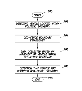
At the point a vehicle is detected as being located within a political
boundary, a
geo-fence boundary is automatically established corresponding to the size and
shape of the political boundary (block 704). Once the geo-fence is
established, the
monitoring system 124, in conjunction with the computer system 126, monitors
movement of vehicle 120 with respect to the geo-fence boundary and data is
collected based on the movement of the vehicle within the geo-fence boundary
(block 706). The method then moves to detecting that the vehicle has departed
the geo-fence boundary (block 708). Thereafter, the method ends (block 710).
[0052] From the description provided herein, those skilled in the art are
readily
able to combine software created as described with appropriate general-purpose
or special-purpose computer hardware to create a computer system and/or
computer sub-components in accordance with the various embodiments, to create
a computer system and/or computer sub-components for carrying out the methods
13
CA 02878392 2015-01-05
WO 2014/011445 PCT/US2013/049090
of the various embodiments and/or to create a non-transitory computer-readable
medium (i.e., not a carrier wave) that stores a software program to implement
the
method aspects of the various embodiments.
[0053] References to "one embodiment," "an embodiment," "some
embodiments," "various embodiments", or the like indicate that a particular
element or characteristic is included in at least one embodiment of the
invention.
Although the phrases may appear in various places, the phrases do not
necessarily refer to the same embodiment.
[0054] The above discussion is meant to be illustrative of the principles and
various embodiments of the present invention. Numerous
variations and
modifications will become apparent to those skilled in the art once the above
disclosure is fully appreciated. For example, while the various embodiments
have
been described in terms of a vehicle is traveling within a state. This
context,
however, shall not be read as a limitation as to the scope of one or more of
the
embodiments described ¨ the same .iechniques may be used for other automatic
geo-fence establishing, vehicle movement detection, and data calculation. It
is
intended that the following claims be interpreted to embrace all such
variations
and modifications,
14