Note: Descriptions are shown in the official language in which they were submitted.
CA 02878403 2015-01-05
WO 2014/005817
PCT/EP2013/062250
Integrated process for native CO2 recovery from a sour gas comprising H2S and
CO2
Field of the invention
The present invention relates to the removal of sulfur components and carbon
dioxide
contained in a hydrocarbon feed stream in order to recover the native carbon
dioxide in a
purified stream. More specifically, the present invention relates to a process
for recovering
native CO2 from a sour gas which contains CO2, H2S and other sulfur compounds,
so that the
recovered CO2 may be then sequestered or used for enhanced oil recovery (EOR).
Besides, the
present invention concerns an installation for implementing such process.
Background
Natural gas or gases associated to oil productions produced from geological
reservoirs, or
refinery acid gases often contain(s) acid contaminants, such as carbon dioxide
and/or
hydrogen sulfide and/or other sulfur compounds, such as mercaptans, COS, CS2,
S .... For most
of the applications of these gas streams, the acid contaminants need to be
removed, either
partially or almost completely, depending on the application and the type of
contaminant.
Methods to remove carbon dioxide and/or hydrogen sulfide and/or other sulfur
compounds
from a hydrocarbon stream are known in the prior art.
One common approach to remove acid contaminants involves the use of solvents
such as
chemical solvent (amine-based solvent), hybrid solvent or physical solvent.
These solvents
have been largely disclosed in the art. However, if appreciable levels of
sulfur compounds are
present in the acid gas, the most common process to eliminate hydrogen sulfide
is to convert
said hydrogen sulfide into a non-hazardous product such as elemental sulfur,
by sending it to a
sulfur recovery unit ("SRU").
The Claus process is a known type of sulfur recovery process allowing the
conversion of
hydrogen sulfide into elemental sulfur. In a first step of said Claus process,
the hydrogen
sulfide is partially burned with air in a Claus furnace to form sulfur dioxide
that will react, in a
second step, with hydrogen sulfide to form elemental sulfur according to the
following
reactions:
(1) 2 H2S + 3 02 2 SO2 + 2 H20
(2) 2 H2S + SO2 t, 3 S + 2 H20
CA 02878403 2015-01-05
WO 2014/005817
PCT/EP2013/062250
2
In some embodiments, remaining H2S traces are captured in a Tail Gas Treatment
Unit (TGTU),
positioned at the outlet of the Claus unit to increase significantly sulfur
recovery.
At the outlet of the TGTU, native CO2 is diluted by a large amount of nitrogen
coming from the
air used for Claus combustion. To recover a purified CO2 stream, CO2 capture
technologies
using solvent (for example an amine based solvent, such as methylethanolamine
(MEA) can be
used. However, since the CO2 is diluted in a large volume of nitrogen, the
amine based CO2
capture unit requires large size equipments, thereby impacting both CAPEX and
OPEX.
Furthermore, an incinerator is generally connected at the outlet of the amine
based CO2
capture unit in order to incinerate continuously the remaining traces of
sulfur compounds,
hydrogen, carbon monoxide and hydrocarbons. It leads to significant fuel gas
consumption and
to important gaseous CO2 emissions, which constitutes a major drawback of such
methods
known in the art.
Therefore, there is a need for a method that allows recovering native CO2 from
a hydrocarbon
feed gas stream which contains acidic compounds, such as CO2, H2S and other
sulfur
compounds, with better yields, lower investments, lower CO2-emissions and
reduced energy
consumption compared with the processes of the prior art.
The present invention meets all these needs by providing a method wherein:
- A purified CO2 stream comprising at least 90 % of CO2 may be recovered,
An oxygen-rich stream is used as a combustive agent for the Claus unit,
thereby reducing the size and cost of the equipments,
- Hydrogen may be efficiently separated from the CO2 stream and recovered,
- An incinerator which works continuously is not required, thereby reducing
the energy consumption of the system and the carbon dioxide emission in the
atmosphere,
Part of the CO2 stream may be recycled into the Claus furnace to cool it down
and facilitate the oxygen-rich operations;
Unless otherwise indicated, all percentages mentioned in the present patent
application are
expressed as molar percentages.
0085350-177
3
Summary
Method
In accordance with a first aspect, a method is provided for treating a
hydrocarbon feed gas stream
containing at least carbon dioxide and hydrogen sulfide to recover a purified
CO2 gas stream (vii), said
process comprising the following steps:
a. separating said hydrocarbon feed gas stream into a sweetened hydrocarbon
gas stream (i), and an
acid gas stream (ii) comprising at least carbon dioxide and hydrogen sulfide;
b. introducing said acid gas stream (ii) into a Claus unit, wherein an oxygen-
rich stream is used as a
combustive agent in the Claus furnace, thereby recovering a liquid stream of
elemental sulfur (iii)
and a tail gas stream (iv) mainly comprising carbon dioxide, hydrogen and
sulfur compounds;
c. introducing the exiting tail gas stream (iv) into a Tail Gas Treatment Unit
(TGTU) thereby
separating said tail gas stream into a CO2 enriched gas .stream also
containing hydrogen and
sweetened in sulfur compounds (v), and a gas stream enriched in sulfur
compounds (vi);
d. compressing the CO2 enriched gas stream (v) exiting the TGTU;
e. passing the compressed CO2 enriched gas stream through a CO2 purification
unit thereby
recovering a purified CO2 gas stream (vii).
In one embodiment, the combustive agent used in the Claus furnace of the Claus
unit is an oxygen-rich
stream, wherein the amount of nitrogen does not exceed 50% is preferably less
than 40% more preferably
less than 20%, and more preferably less than 10%.
In one embodiment, the tail gas stream (iv), the CO2 enriched gas stream (v)
and the purified CO2 gas
stream (vii) also contain nitrogen.
In one embodiment, the acid gas stream (ii) is enriched in H2S by an acid gas
enrichment unit located
upstream the Claus unit.
In one embodiment, the TGTU comprises a feed inline burner or a tail gas
heater, a hydrogenation reactor,
a quench contactor and optionally an absorber unit, in particular an absorber
unit based on amine.
CA 2878403 2019-09-17
0085350-177
4
In one embodiment, a CO2 enriched gas stream exiting the compression unit is
dehydrated before entering
the CO2 purification unit.
In one embodiment, the CO2 purification unit is cryogenic separation unit
producing a purified CO2 gas
stream (vii) and a lean CO2 stream (viii).
In one embodiment, the CO2 purification unit is a membrane unit producing a
purified CO2 gas stream (vii)
on the residue side and a lean CO2 stream (viii) on the permeate side.
In one embodiment, the CO2 purification unit is an adsorption unit producing a
purified CO2 gas stream
(vii) and a lean CO2 stream (viii).
In one embodiment, the CO2 purification is an absorption unit producing a
purified CO2 gas stream (vii) and
a lean CO2 stream (viii).
In one embodiment, the CO2 purification unit is a combination of CO2
purification units.
In one embodiment, part of the Claus tail gas stream (iv) is recycled into the
Claus furnace before
introduction to the TGTU
In one embodiment, part of the gas stream inside the Claus unit is recycled
into the Claus furnace by
internal recycling.
In one embodiment, part of the gas stream exiting the quench tower of the TGTU
is recycled into the Claus
furnace before introduction to the absorber unit.
CA 2878403 2019-09-17
0085350-177
4a
In one embodiment, part of the purified CO2 gas stream (vii) exiting the CO2
purification unit recycled
into the Claus furnace.
In one embodiment, part of the lean CO2 stream (viii) exiting the CO2
purification unit is recycled
upstream of or directed in the Claus furnace.
In one embodiment, part of the CO2 stream (viii) exiting the CO2 purification
unit is recycled between
the Claus unit and the hydrogenation reactor of the TGTU.
In one embodiment, step d) is eliminated.
In accordance with another aspect, a method is provided for treating a
hydrocarbon feed gas stream
containing at least carbon dioxide and hydrogen sulfide to recover a purified
CO2 gas stream. The
method comprises the following steps:
a. separating said hydrocarbon feed gas stream into a sweetened hydrocarbon
gas stream,
and an acid gas stream comprising at least carbon dioxide and hydrogen
sulfide;
b. introducing said acid gas stream into a Claus unit wherein an oxygen-rich
stream is used as
a combustive agent in the Claus furnace, wherein the oxygen-rich stream
contains an
amount of nitrogen that is at most 50%, thereby recovering a liquid stream of
elemental
sulfur and a tail gas stream mainly comprising carbon dioxide, hydrogen and
sulfur
compounds;
c. introducing the tail gas stream into a Tail Gas Treatment Unit
(TGTU) comprising:
a. at least one of a feed inline burner and a tail gas heater;
b. a hydrogenation reactor; and
c. a quench contactor;
thereby separating said tail gas stream into a CO2 enriched gas stream also
containing
hydrogen and sweetened in sulfur compounds, and a stream enriched in sulfur
compounds;
d. passing the CO2 enriched gas through a CO2 purification unit thereby
recovering a purified
CO2 gas stream.
CA 2878403 2019-09-17
CA 02878403 2015-01-05
WO 2014/005817
PCT/EP2013/062250
Device
The present invention also relates to a device for carrying out the method as
described above.
The device of the present invention comprises in the direction of flow:
- an acid gas removal unit providing an acid gas stream;
5 - a Claus unit operated with an oxygen-rich stream;
- a tail gas treatment unit removing sulfur components;
- a compression device; and
- a CO2 purification device.
In one embodiment, the tail gas treatment unit comprises a feed inline burner
or a tail gas
heater, a hydrogenation reactor, a quench contactor and optionally an absorber
unit, in
particular an absorber unit based on an amine.
In one embodiment, the device further comprises an acid gas enrichment unit
located
upstream the Claus unit.
In one embodiment, the device further comprises a dehydration device.
In one embodiment, the CO2 purification device is a cryogenic separation unit.
In one embodiment, the CO2 purification device is a membrane unit.
In one embodiment, the CO2 purification device is an adsorption unit.
In one embodiment, the CO2 purification device is an absorption unit.
In one embodiment, the CO2 purification device is a combination of CO2
purification units.
In one embodiment, the device further comprises a recycle line for collecting
part of the gas
stream between the Claus unit and the TGTU and injecting it into the Claus
furnace.
In one embodiment, the device further comprises a recycle line for collecting
part of the gas
stream inside the Claus unit and injecting it into the Claus furnace by
internal recycling.
In one embodiment, the device further comprises a recycle line for collecting
part of the gas
stream between the quench tower and the absorber unit of the TGTU and
injecting into the
Claus furnace.
CA 02878403 2015-01-05
WO 2014/005817
PCT/EP2013/062250
6
In one embodiment, the device further comprises a recycle line for collecting
part of the
purified CO2 gas stream (vii) exiting the CO2 purification unit and injecting
into the Claus
furnace.
In one embodiment, the device further comprises a recycle line for collecting
part of the lean
CO2 stream (viii) exiting the CO2 purification unit and injecting upstream of
or directly into the
Claus furnace.
In one embodiment, the device further comprises a recycle line for collecting
part of the lean
CO2 stream (viii) exiting the CO2 purification unit and injecting between the
Claus unit and the
hydrogenation reactor of the TGTU.
Brief description of the figures
Figure 1 is a schematic view of a classical native CO2 recovery unit, as known
in the prior art.
Figure 2 is a schematic view of the native CO2 recovery unit for performing
the method of the
present invention.
Figure 3 is a schematic view of the native CO2 recovery unit for performing
the method of the
present invention, wherein the CO2 purification uses a membrane unit.
Figure 4 is a schematic view of the native CO2 recovery unit for performing
the method of the
present invention, wherein the CO2 purification uses a cryogenic separation
unit.
Detailed description of the invention
The process according to the invention applies to the treatment of a
hydrocarbon gas stream
containing acid contaminants, such as a natural gas stream or refinery gas
stream. The acid
contaminants are mainly composed of carbon dioxide and hydrogen sulfide.
However, the gas
stream may also contain other acid contaminants, like sulfur compounds, in
particular
mercaptans.
Typically, the hydrocarbon feed gas stream may contain (on a dry basis) from 1
% to 70 % of
CO2, in particular from 2 % to 40 % of CO2, more particularly from 3 % to 20 %
of CO2, and from
0.5% to 50 % of H2S, in particular from 0.5 % to 40 % of H2S, more
particularly from 0.5 % to 20
% of H2S.
CA 02878403 2015-01-05
WO 2014/005817
PCT/EP2013/062250
7
According to step a) of the method of the invention, the hydrocarbon feed gas
stream is
separated into a sweetened hydrocarbon gas stream (i), and an acid gas stream
(ii) comprising
at least carbon dioxide and hydrogen sulfide.
By "sweetened hydrocarbon gas stream", it is meant a hydrocarbon gas stream
containing less
acid contaminants than the hydrocarbon feed gas stream. The acid gas stream
(ii), on the other
hand, is enriched in acid contaminants compared to the hydrocarbon feed gas
stream.
Methods for obtaining a sweetened hydrocarbon gas stream (i) and acid gas
stream (ii) from a
hydrocarbon feed gas stream containing acid contaminants are well known by the
person
skilled in the art. Any sweetening method may be used for performing step a)
of the present
invention. Such methods include solvent treatment, such as chemical solvent
treatment, in
particular amine based solvent treatment, hybrid solvent treatment or physical
solvent
treatment.
Typically, the acid gas stream (ii) contains (on a dry basis) from 10 % to 90
% of CO2, in
particular from 25 % to 75 % of CO2, and from 10 % to 90 % of H2S, in
particular from 25 % to
75 % of H2S.
According to step b) of the method of the invention, the acid gas stream (ii)
is then introduced
into a Claus unit wherein an oxygen-rich stream (also named "oxygen or oxygen
plus air") is
used as a combustive agent in the Claus furnace (also named combustion
furnace), thereby
recovering (iii) a liquid stream of elemental sulfur (iii) and a tail gas
stream (iv) mainly
comprising carbon dioxide, hydrogen and sulfur compounds.
In one embodiment, the acid gas stream (ii) is enriched in an acid gas
enrichment unit located
upstream the Claus unit to increase the H2S content in the acid gas stream
(ii).
As explained previously, a Claus unit allows the conversion of hydrogen
sulfide into elemental
sulfur according to the following reactions:
(1) 2 H2S + 3 02 2 SO2+ 2 H20
(2) 2 H2S + SO2 3 S + 2 H20.
In a Claus unit, air is generally used as a combustive agent for the
conversion of hydrogen
sulfide into sulfur dioxide. However, since air contains around 80% of
nitrogen and 20% of
CA 02878403 2015-01-05
WO 2014/005817
PCT/EP2013/062250
8
oxygen, the use of air as a combustive agent results in large volume of
nitrogen in the process
gas stream, which in turn requires equipments of large size.
According to the present invention, an oxygen-rich stream is used as a
combustive agent,
instead of air, in order to reduce the process gas volume. By "oxygen-rich
stream", it is meant
a stream containing an amount of oxygen from 20% to 100%, preferably from 70%
to 100%
and more preferably from 97% to 100%. The balanced components can be CO2, N2,
Ar, Xe, H2,
H20, etc....
In one embodiment, the combustive agent used in the Claus furnace of the Claus
unit is an
oxygen-rich stream, wherein the amount of nitrogen does not exceed 50%, is
preferably less
than 40%, more preferably less than 20%, and more preferably less than 10%.
The oxygen-rich stream may be obtained from atmospheric air by using an air
separation unit
(ASU) which separates atmospheric air into its primary components: mostly
nitrogen and
oxygen, and sometimes also argon and other rare inert gases. Any suitable
method of
separation may used in the process of the invention, for instance cryogenic
distillation.
The above described Claus reactions are strongly exothermic. Typically, the
pressure in the
Claus furnace is from 1.7 to 1.9 bara and the temperature should be maintained
between 900
C and 1450 C. The hot gas from the combustion chamber passes through steps of
reaction
and condensation to produce liquid elemental sulfur (iii).
The use of an oxygen-rich stream as a combustive agent in the Claus furnace
promotes side
reactions resulting in the formation of hydrogen. The tail gas stream (iv)
downstream the Claus
unit thus contains minor amounts of hydrogen.
Thus, according to the invention, the tail gas stream (iv) recovered at the
exit of the Claus unit
mostly contains carbon dioxide and water, but also contains a certain amount
of hydrogen,
nitrogen and possibly carbon monoxide, as well as traces of sulfur compounds,
such as
hydrogen sulfide and sulfur dioxide.
Depending on the CO2 purification technology, the nitrogen content in the
oxygen-rich stream
may be adjusted depending on the content of nitrogen that can be accepted in
the purified
CO2 stream.
CA 02878403 2015-01-05
WO 2014/005817
PCT/EP2013/062250
9
The tail gas stream (iv) exiting the Claus unit generally contains (on a dry
basis) at least 40 % of
CO2, preferably from 50% to 90% of CO2. Balanced components can be H2, N2,
H2S, SO2, CO, Ar,
COS, etc...
According to step c) of the method of the invention, the tail gas stream (iv)
exiting the Claus
.. unit is introduced into a Tail Gas Treatment Unit (TGTU), thereby
separating said tail gas
stream (iv) into a CO2 enriched gas stream (v) containing hydrogen and
sweetened in sulfur
compounds, and a gas stream enriched in sulfur compounds (vi).
The TGTU allows the conversion of the sulfur compounds of the tail gas stream
(iv) into H2S.
In one embodiment, the TGTU comprises four main equipments in the direction of
flow:
- a feed inline burner or a tail gas heater for heating the tail gas stream
(iv),
- a hydrogenation reactor for converting the sulphur compounds of the tail
gas
stream (iv) into H2S,
- a quench contactor removing extra water from the gas stream and
- an absorber unit (amine-based) for separating the sulfur compounds
(mainly H2S)
from the other constituents of the tail gas stream (iv).
The TGTU includes amine based tail gas treatment units or subdew point tail
gas treatment or
direct oxidation based tail gas treatment units. The TGTU used to implement
the method of
the invention is not limited to these TGTUs. Any type of TGTU may be suitable
for
implementing the method of the invention.
As a result, two streams are recovered at the exit of the TGTU: a CO2 enriched
gas stream
containing hydrogen (v), and a gas stream enriched in sulfur compounds (vi)
(i.e. containing
more sulfur compounds than the tail gas (iv)) in the other hand.
Typically, the gas stream enriched in sulfur compounds (vi) is introduced into
the Claus unit.
The feed inline burner/ or tail gas heater positioned upstream of the
hydrogenation reactor
provides the heat and hydrogenation/ or heat.
The hydrogenation reactor typically comprises a catalyst bed where sulphur
compounds such
as SO2, S, COS and CS2 are converted into H2S. The hydrogenated stream is then
passed
CA 02878403 2015-01-05
WO 2014/005817
PCT/EP2013/062250
through a quench contactor, preferably a water-quench tower, in order to
reduce temperature
and remove extra water.
The gas stream at quench outlet exiting the quench tower is then passed
through an absorber
unit, wherein sulfur compounds, mainly H2S, are absorbed by an absorbing
solution.
5 Preferably, the absorber unit is an amine-based. A CO2 enriched gas
stream (v) is thus
recovered from the absorber unit, that contains less than 500 ppm of H2S,
preferably less than
100 ppm of H2S. The sulfur-containing stream is separated from the absorbing
solution and
recycled back to the Claus furnace.
Alternatively, the gas stream recovered at quench outlet may not be passed
through the
10 .. absorber unit if the content of H2S in the CO2 stream is lower than the
required H2S
specification in the purified CO2 stream. In that case, the TGTU only
comprises a feed inline
burner or a tail gas heater, a hydrogenation reactor and a quench contactor.
At the exit of the TGTU, the CO2 enriched gas stream (v) generally contains
(on a dry basis) at
least 40% of carbon dioxide, preferably from 50% to 90% of carbon dioxide.
In one embodiment, the CO2 enriched gas stream (v) also comprises nitrogen due
to the
presence of nitrogen in the oxygen-rich stream used as a combustive agent.
In other embodiments, according to step d) of the method of the invention, the
CO2 enriched
gas stream (v) exiting the TGTU is compressed, preferably at a pressure from
10 bar to 100 bar,
more preferably from 20 bar to 60 bar. Of course, the compression step may be
eliminated if
the purification technology does not require it.
In one embodiment, the compressed CO2 enriched gas stream is passed through a
dehydration
unit in order to complete the removal of water contained in the CO2 stream.
Preferably, the
dehydration unit is a glycol or an adsorption unit but any other suitable
dehydration technique
may be used.
According to step e) of the method of the invention, the compressed CO2
enriched gas stream
is then passed through a CO2 purification unit, such as CO2/H2 separation
unit, thereby
recovering a purified CO2 gas stream (vii) in one hand and a lean CO2 stream
(viii) in the other
hand, which comprises hydrogen.
CA 02878403 2015-01-05
WO 2014/005817
PCT/EP2013/062250
Any suitable CO2 purification unit may be used. Preferably, the CO2
purification unit is a
cryogenic separation unit, a membrane unit, an adsorption unit, an absorption
unit or a
combination thereof.
The cryogenic separation unit produces a purified CO2 gas stream (vii) and a
non-condensable
stream (viii) containing H2, CO2, N2, Ar, etc.... which may be thus recovered
for further use.
As for membrane separation, the CO2 recovery rate is generally lower than that
of cryogenic
separation. However, since the membrane permeate comprises a large amount of
carbon
dioxide, it may be advantageously recycled to the Claus furnace in order to
facilitate the
oxygen-rich operations. In the case of membrane separation, the CO2 recovery
rate may be
increased by recycling totally or part of the membrane permeate into the Claus
furnace.
In case of low CO2 content in the compressed CO2 enriched gas stream, a
combination of CO2
purification units can be advantageously implemented to increase CO2 recovery.
The CO2 stream may be required to control the Claus furnace temperature and
recycled at
different stages of the process. Preferably, the recycled CO2 stream is
collected as upstream as
possible in order to reduce the volume of gas to be treated by the downstream
units.
In one embodiment, part of the gas stream exiting the quench tower of the TGTU
is recycled
into the Claus furnace before introduction to the absorber unit.
In one embodiment, part of the gas stream (iv) exiting the Claus unit is
recycled into the Claus
furnace before introduction to the TGTU.
In one embodiment, part of the gas stream inside the Claus unit is recycled
into the Claus
furnace by internal recycling.
In one embodiment, part of the purified CO2 gas stream (vii) exiting the CO2
purification unit is
recycled into the Claus furnace.
In one embodiment, part of the lean CO2 stream (viii) exiting the CO2
purification unit is
recycled between the Claus unit and the hydrogenation reactor of the TGTU.
In one embodiment, part of the lean CO2 stream (viii) exiting the CO2
purification unit is
recycled upstream of or directly in the Claus furnace.
A combination of these recycles may be also performed.
CA 02878403 2015-01-05
WO 2014/005817
PCT/EP2013/062250
12
The purified CO2 stream (vii) obtained by the method of the invention may
contain from 90 %
to 100 % of CO2, preferably from 97 % to 99.9 % of CO2. It may be then
sequestered or used for
enhanced oil recovery ([OR).
In one embodiment, the purified CO2 gas stream (vii) also contains nitrogen
due to the
presence of nitrogen in the oxygen-rich stream used as a combustive agent.
As previously mentioned, the purity of the CO2 stream obtained by the method
of the
invention will depend on the type of combustive agent used in the Claus
furnace, on the TGT
technology and on the CO2 purification technology. To obtain a CO2 stream of
high purity (98%
or more), it is preferable to use high purity oxygen-rich stream (to Claus
furnace). However, for
a lower purity of produced CO2 rich stream, lower purity of oxygen-rich stream
(to Claus
furnace) may be preferable because it is less expensive to implement.
Another object of the present invention is a device for carrying the method of
the invention as
previously described, said device comprising in the direction of flow:
- an acid gas removal unit providing an acid gas stream;
- a Claus unit operated with an oxygen-rich stream;
- a tail gas treatment unit removing sulfur components;
- a compression device; and
- a CO2 purification device.
The acid gas removal unit may be a unit performing a classical sweetening
method such as
chemical, hybrid or physical solvent. It may be for instance an amine washing
unit. Amine
solutions are well known by the person skilled in the art. According to the
desired
specification, the amine solutions may include DEA (di-ethanol amine), MDEA
(methyl-di-
ethanol amine) or activated MDEA or any other solution.
As previously mentioned, the combustive agent for the Claus unit may be an
oxygen-rich
stream. The oxygen-rich stream may be produced by an air separation unit. In
addition, part of
the purified CO2 stream (vii) may be recycled into the Claus unit to
facilitate the oxygen-rich
operations.
In one embodiment, the device further comprises an acid gas enrichment unit
located
between the acid gas removal unit and the Claus unit to increase the H2S
content in the
.. stream.
CA 02878403 2015-01-05
WO 2014/005817
PCT/EP2013/062250
13
In one embodiment, the tail gas treatment unit (TGTU) comprises in the
direction of flow a
feed inline burner/or a tail gas heater, a hydrogenation reactor, a quench
contactor and
optionally an absorber unit, in particular an absorber unit based on amine. As
previously
explained, it may not be necessary to include an absorber unit in the TGTU if
the content of
H2S in the CO2 stream at the exit of the hydrogenation reactor is lower than
the required
specification in the purified CO2 stream. In that case, the TGTU only
comprises a feed inline
burner/or a tail gas heater, a hydrogenation reactor and a quench contactor.
In one embodiment, TGTU includes subdew point tail gas treatment or direct
oxidation based
tail gas treatment units. The TGTU used to implement the method of the
invention is not
limited to these TGTUs. Any type of TGTU may be suitable for implementing the
method of the
invention.
In one embodiment, the device further comprises a dehydration device located
upstream the
CO2 purification device. Depending on the compression configuration,
dehydration can be
located between two compression stages. Preferably, the CO2 purification
device is a cryogenic
separation unit, a membrane unit, an adsorption unit or an absorption unit.
In one embodiment, the CO2 purification device is a combination of CO2
purification
technologies.
The device may further comprise a one or several recycle lines as follows:
- a recycle line for collecting part of the gas stream (iv) between the
Claus unit
and the TGTU and injecting into the Claus furnace;
- a recycle line for collecting part of the gas stream inside the Claus
unit is
recycled into the Claus furnace,
- a recycle line for collecting part of the gas stream between the quench
tower
of the TGTU and the absorber unit and injecting into the Claus furnace,
- a recycle line for
collecting part of the purified CO2 gas stream (vii) exiting the
CO2 purification unit and injecting into the Claus furnace,
- a recycle line for collecting part of the lean CO2 stream (viii) exiting
the CO2
purification unit and injecting between the Claus unit and the hydrogenation
reactor of the TGTU,
- a recycle line for
collecting part of the lean CO2 stream (viii) exiting the CO2
purification unit and injecting upstream of or directly into the Claus
furnace.
CA 02878403 2015-01-05
WO 2014/005817
PCT/EP2013/062250
14
The invention is further described in the figures 1, 2, 3 and 4. These
examples are offered to
illustrate the invention and should in no way be viewed as limiting the
invention.
Figure 1 provides a schematic view of a classical CO2 recovery unit, as known
in the prior art.
.. In figure 1, a sour gas stream is introduced into an acid gas removal unit
(AGRU), thereby
providing a sweet gas stream and an acid gas stream containing 48% of carbon
dioxide and
43% of hydrogen sulfide. The acid gas stream then enters a Claus unit at a
pressure of 1-2 bar.
In the Claus unit the hydrogen sulfide is converted into elemental sulfur
using air containing
20% of oxygen and 80% of nitrogen as a combustive agent, therefore leading to
the dilution of
carbon dioxide with nitrogen. Then, this mixture enters a Tail Gas Treatment
Unit (TGTU) to
remove remaining traces of sulfur compounds, leading to a tail gas stream
mixture composed
of 60% of nitrogen, 30% of carbon dioxide and 10% of water. At the outlet of
the TGTU, said
mixture is then contacted with an amine-based solvent in order to capture the
carbon dioxide,
thereby separating the carbon dioxide from remaining nitrogen.
Typically, MethylEthanolAmine (MEA) is used as the most common amine solvent
to capture
the CO2 from TGT off gas. After the step of absorption, the chemical amine
solvent enriched in
carbon dioxide is sent to a regenerator operating at a pressure comprised
between 1 and 2
bara to recover the amine solvent depleted in carbon dioxide and to provide a
stream of
gaseous carbon dioxide saturated with water. After the steps of compression
and dehydration
(typically using a TEG unit), a stream composed of about 99.9% of carbon
dioxide and 600 ppm
of hydrogen sulfide is obtained.
The remaining mixture exiting the CO2 capture absorber comprising 87% of
nitrogen, 4% of
carbon dioxide, 6% of water and 3% of hydrogen is sent to the incinerator.
As a result typical native CO2 recovery of such capture is about 90%.
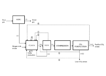
Figure 2 provides a schematic view of a native CO2 recovery unit for
performing the method of
the present invention.
In figure 2, a sour gas stream is introduced into an acid gas removal unit
(AGRU), thereby
providing a sweet gas stream (i) and an acid gas stream (ii) containing 48% of
carbon dioxide
and 43% of hydrogen sulfide. A classical sweetening method using a chemical, a
hybrid or a
CA 02878403 2015-01-05
WO 2014/005817
PCT/EP2013/062250
physical solvent is used as an Acid Gas Removal Unit (AGRU). The acid gas
stream (ii) then
enters a Claus unit using oxygen-rich stream at a pressure of 1.7-1.9 bar.
Matter of fact, the
hydrogen sulfide is transformed into elemental sulfur in the Claus unit using
oxygen-rich
stream as a combustive agent. Two streams exit from the Claus unit: a stream
of elemental
5 sulfur
(iii) and a tail gas stream (iv) mainly comprising CO2, H2 and sulfur
compounds. Then, the
tail gas stream (iv) enters a Tail Gas Treatment Unit (TGTU) in order to
remove remaining
traces of sulfur compounds, thereby producing a gas effluent (v) composed of
85% of carbon
dioxide, 10% of hydrogen, 5% of water and 100 ppm of hydrogen sulfide. Then,
this gas
effluent (v) enters the compression unit, then a CO2 purification unit,
thereby forming, on the
10 one hand, a
purified carbon dioxide stream (vii) and, on the other hand, a lean carbon
dioxide
stream (viii) comprising carbon dioxide and hydrogen.
The composition of the purified carbon dioxide stream (vii) and of the lean
CO2 stream (viii)
will depend on the type of separation technology.
One or several recycle lines may be included in the process:
15 - recycle
line 10, wherein part of the gas stream exiting the quench tower is
recycled into the Claus furnace before introduction to the absorber unit,
- recycle line 0, wherein part of the gas stream (iv) exiting the Claus
unit is
recycled into the Claus furnace before introduction to the TGTU,
- recycle line 3, wherein part of the gas stream inside the Claus unit is
recycled
into the Claus furnace by internal recycling,
- recycle line , wherein part of the purified CO2 gas stream (vii) exiting
the CO2
purification unit is recycled into the Claus furnace,
- recycle line 0, wherein part of the lean CO2 stream (viii) exiting the
CO2
purification unit is recycled between the Claus unit and the hydrogenation
reactor
of the TGTU,
- recycle line , wherein part of the lean CO2 stream (viii) exiting the
CO2
purification unit is recycled upstream of or directly into the Claus furnace.
Figure 3 provides a schematic view of a native CO2 recovery unit for
performing the method of
the present invention, wherein the CO2 purification unit is a membrane.
In figure 3, a sour gas stream is introduced into an acid gas removal unit
(AGRU), thereby
providing a sweet gas stream (i) and an acid gas stream (ii) containing 48% of
carbon dioxide
and 43% of hydrogen sulfide. A classical sweetening method using a chemical, a
hybrid or a
CA 02878403 2015-01-05
WO 2014/005817
PCT/EP2013/062250
16
physical solvent is used as an Acid Gas Removal Unit (AGRU). The acid gas
stream (ii) then
enters a Claus unit using oxygen-rich stream as a combustive agent in the
Claus furnace, at a
pressure of 1.7-1.9 bar. Two streams exit from the Claus unit: a stream of
elemental sulfur (iii)
and a tail gas stream (iv) mainly comprising CO2, H2 and sulfur compounds.
Then, the tail gas
.. stream (iv) enters a Tail Gas Treatment Unit (TGTU), said TGTU being an
amine based
technology, thereby producing a gas effluent (v) composed of 85% of carbon
dioxide, 8% of
hydrogen, 7% of water and 100 ppm of hydrogen sulfide. Then, this gas effluent
(v) enters a
compression unit and a dehydration unit, then a membrane unit for CO2
purification, thereby
forming a purified carbon dioxide residue and a permeate stream containing
carbon dioxide
and hydrogen.
The purified carbon dioxide residue stream (vii), at a pressure close to the
compression unit
discharge pressure, is composed of 98% of carbon dioxide, 1.7% of hydrogen,
0.3% of carbon
monoxide and less than 100 ppm of hydrogen sulfide. The permeate stream
(viii), at about 2
bara is composed of approximately 70% of carbon dioxide and 30% of hydrogen.
Said
membrane permeate stream (viii) is totally or partially recycled upstream of
or directly in the
Claus unit. As a result of total recycle, typical native CO2 recovery of this
process scheme is
about 100%.
Figure 4 provides a schematic view of a native CO2 recovery unit for
performing the method of
the present invention, wherein the CO2 purification unit is a cryogenic unit.
.. In figure 4, a sour gas stream is introduced into an acid gas removal unit
(AGRU), thereby
providing a sweet gas stream (i) and an acid gas stream (ii) containing 18% of
carbon dioxide
and 73% of hydrogen sulfide. A classical sweetening method using a chemical, a
hybrid or a
physical solvent is used as an Acid Gas Removal Unit (AGRU). The acid gas
stream (ii) then
enters a Claus unit using oxygen-rich stream as a combustive agent in the
Claus furnace, at a
pressure of 1.7-1.9 bar. Two streams exit from the Claus unit: a stream of
elemental sulfur (iii)
and a tail gas stream (iv) mainly comprising CO2, H2 and sulfur compounds.
Then, the tail gas
stream (iv) enters a Tail Gas Treatment Unit (TGTU), said TGTU being an amine
based
technology. Part of the gas stream after the quench tower is recycled to the
Claus furnace,
with a composition of 59% CO2, 20% H2 and 4% H2S. Downstream the TGT amine, a
gas effluent
(v) is produced, composed of 58% of carbon dioxide, 23% of hydrogen, 15% of
water and 500
ppm of hydrogen sulfide. Then, this gas effluent (v) enters a compression unit
and a
CA 02878403 2015-01-05
WO 2014/005817
PCT/EP2013/062250
17
dehydration unit, then a cryogenic unit for CO2 purification, thereby forming
a purified carbon
dioxide product (vii) and a lean CO2 stream (viii) containing hydrogen and
some carbon dioxide.
The purified carbon dioxide stream (vii), at around 10 bara, is composed of
99.9% of carbon
dioxide and less than 0.1% of hydrogen sulfide. The lean CO2 stream (viii)
rich in hydrogen (viii),
at about 1.3 bara is composed of approximately 72% of hydrogen and 14% of
carbon dioxide,
remaining components being argon, carbon monoxide, nitrogen.