Note: Descriptions are shown in the official language in which they were submitted.
CA 02878409 2015-01-06
Method for controlling an electric generator
The present invention relates to a method for controlling a generator of
electric energy
that is connected to an electrical supply grid on a grid connection point.
Furthermore, the
present invention relates to a generator of electric energy that is connected
to an electri-
cal supply grid.
Feeding electric energy into an electrical supply grid, such as the European
grid or the
US power grid, is generally known. The electrical supply grid as described
below refers to
the widely accepted AC voltage grid. This does not exclude the presence of DC
voltage
sections in the grid. Likewise, frequency-independent aspects may generally
also refer to
a DC voltage grid. Historically, energy is fed into an electrical supply grid
with a large
power station that drives a synchronous generator using primary energy, such
as coal,
nuclear energy or gas. Depending on the number of pole pairs and the speed of
the
synchronous generator, this generator feeds into the supply grid with a
certain frequency.
The synchronous generator may be technically controlled so as, for example, to
adjust
the output. However, this adjustment process can take a long time.
With changing situations in the supply grid, the physical reaction of the
synchronous
generator often causes a change in the grid condition, at least for a short
time. For exam-
ple, the speed of the synchronous generator increases if the supply grid is
not able to
take the power completely that is or can be provided by the synchronous
generator. This
excess power then accelerates the synchronous generator, which results in an
increased
feeding frequency. Accordingly, the frequency in the supply grid may increase.
When feeding into a supply grid, the network stability must also be taken into
account.
The loss of network stability, i.e., the loss of the stability of the supply
grid, may result in
the feeding generator being powered off. Such a loss of stability, which is
referred to as
such and abbreviated as "LOS" among German-speaking experts, describes
physical
processes that no longer allow for a continued operation and must be
terminated by
cutoffs. In the case of power plants, this affects their output, and can thus
contribute to an
escalation of the so-called deficit output. In the worst case, this loss of
stability leads to a
total energy system failure due to error cascading and deficit accumulation.
Such total
failures are very rare; however, one occurred in Italy on 24 September 2004.
CA 02878409 2015-01-06
- 2 -
Loss of network stability, i.e. the so-called loss of stability, is a
phenomenon which in-
volves a loss of angular stability that may eventually cause a loss of voltage
stability.
Overcurrents to be achieved are determined as stability criteria, which must
be provided
in the case of a loss of stability. This requires the system to have a certain
design. A new
power plant, in particular a power plant that is to be newly built, is thus
coordinated to the
supply grid as is represented on the grid connection point to which the power
plant is to
be connected.
When connecting large power plants to an electrical supply grid, the short
circuit current
ratio is an important criterion; this is known among German specialists as
"short circuit
radio" and abbreviated as "Scr". This short circuit current ratio is the ratio
of the short
circuit power to the connected load. Short circuit power is the power that the
respective
supply grid on the considered grid connection point, to which the power plant
is to be
connected, can provide in the case of a short circuit. The connected load is
the connected
load of the power plant that is to be connected, in particular the nominal
capacity of the
generator that is to be connected.
To secure reliable operation, i.e., to avoid a loss of stability to the
greatest extent possi-
ble, power plants are generally designed for the respective grid connection
point in such a
way that the short circuit current ratio is higher than 10, normally even
higher than 15.
The supply grid can then provide a relatively high short circuit power on the
grid connec-
tion point. That means that the grid has a low impedance and is referred to as
a strong
grid.
In the case of a weak grid (in other words, in the presence of a high
impedance), feeding
is only possible with a low connected load, i.e., only a power plant with a
low connected
load can be connected. This usually leads to the fact that either a new power
plant is not
connected to such a grid connection point, or the grid has to be changed,
particularly by
equipping it with further, more powerful lines. This is generally referred to
as grid rein-
forcement.
For feeding electric energy by decentralized production units, in particular
wind power
installations, the problem of the grid's loss of stability is basically
unknown. Already at the
end of the nineties, first proposals were made to ensure that wind power
installations also
contribute to the electrical support of the grid. This, however, does not take
into account
the cause of a loss of stability, in particular that feeding into the supply
grid can cause a
loss of stability.
CA 02878409 2015-01-06
- 3 -
For example, the German patent application US 6,891,281 describes a method in
which
wind power installations can change and, in particular, reduce their power
feed-in. US
7,462,946 suggests that in the case of a grid failure, particular in the case
of a short
circuit, a wind power installation limits the power that it feeds-in instead
of being discon-
nected from the grid in order to achieve a grid support. US 6,965,174
describes a method
for supporting the grid by means of a wind power installation that, depending
on the grid
voltage, adjusts a phase angle of the fed-in electricity, and thus feeds
reactive power into
the grid depending on the voltage so as to support the grid. US 6,984,898 also
relates to
a method for supporting the grid by means of a wind power installation in
which the wind
power installation reduces, depending on the grid voltage, the power that is
to be fed into
the grid, particularly so as to avoid a disconnection from the grid in order
to support the
grid by means of a wind power installation.
The fact that such decentralized production units, such as wind power
installations, may
be the underlying cause for the loss of stability in the grid has not been
taken into ac-
count. In the essay "Loss of (Angle) Stability of Wind Power Installations" by
V. Diedrichs
et al., submitted for and presented at the "10th International Workshop on
Large-Scale
Integration of Wind Power into Power Systems as well as on Transmission
Networks for
Offshore Wind Farms, Aarhus (Denmark), 25 - 26 October 2011". There, reference
was
basically made to the problem that the loss of stability in the grid can
basically also occur
for wind power installations that are connected to the supply grid for feed-
in. This essay
essentially raises awareness of the problem. Reference is expressly made to
this essay
and its content. In particular, its technical explanations also apply to the
present applica-
tion.
Basically, findings, experience and other knowledge of the operation and
connection of
large power plants to the electrical supply grid cannot be transferred to wind
power instal-
lations, including large wind parks with numerous wind power installations
that are con-
nected to the supply grid for feed-in. The responsible expert who connects a
power plant
to a supply grid in order to operate it there is already a different expert
from the one
wanting to connect a wind power installation to the supply grid in order to
operate it there.
Wind power installations - and much of the following also applies to
decentralized produc-
tion units - depend on wind and must therefore take a fluctuating energy
source into
account; they usually do not feed into the supply grid with a synchronous
generator that is
directly coupled to the grid, but use a voltage-based inverter instead; they
have a different
size than large power plants, whereby their nominal capacity is usually 3
powers of ten
below that of a large power plant; they are usually subject to other political
laws which
often ensure the acceptance of the provision of service by the operators of
electrical
CA 02878409 2015-01-06
- 4 -
supply grids; they are usually decentralized; and, they usually feed into a
medium-voltage
grid, whereas large power plants usually feed into an extra high voltage grid.
If a loss of stability that is to be avoided occurs in spite of all due
caution and precaution-
ary measures, this leads to a problematic situation. If such a loss of
stability occurs, the
generator of electric energy must be switched off for the concerned grid
connection point.
Such a switching off is triggered according to predetermined criteria, and the
respectively
concerned generator monitors said criteria, and switches off if it has
recognized that said
criteria are met. However, the power that is immediately fed into the grid,
and thus the
existing power in the grid, changes. The loss of said power of said generator
can lead to
the fact that further points of common coupling nearby meet the criteria for
switching off,
and accordingly switch off further generators, which can result in even
further generators
being switched off, which can finally result in a complete blackout of the
entire supply
grid.
The German Patent and Trademark Office has found the following prior art in
the priority
application for the present application: DE 10 2009 027 981 B4, DE 10 2008 062
356 Al,
WO 2011/050807 A2 and DE 10 2008 045 938 Al.
The object of the present invention is to address at least one of the problems
mentioned
above. In particular, a solution is to be proposed which, in the case of the
described loss
of stability in the supply grid, or at least a threatening loss of stability,
minimizes the
threatening damage. An alternative solution should at least be proposed.
According to the invention, a method for controlling a generator of electric
energy that is
connected to an electrical supply grid on a grid connection point is proposed
according to
Claim 1. According to this, electrical power is fed into the electrical
supply, whereby the
generator is operated in a first operating point. Such an operating point can,
for example,
be determined by the fed-in active power and, if the case may be, by the fed-
in reactive
power. Feeding active power in the amount of the nominal capacity of the
generator and
feeding reactive power in the amount of 10% of the fed-in active power serve
as an
example for an operating point here, to name only one example.
Whereas the generator is operated in said first operating point, the feeding
is then inter-
rupted so that no power is fed into the supply grid if a fault in the
electrical supply grid or a
fault of the feeding into the electrical supply grid exists or is displayed.
Therefore, such a
fault is monitored, and if it is detected, an interruption of the feeding is
triggered. Said
interruption is not performed with all minimal faults, but only with faults
that are to trigger
CA 02878409 2015-01-06
- 5 -
said interruption. For this purpose, respective criteria can be determined,
such as an
overly strong voltage drop, or an overly strong gradient of a voltage drop on
the grid
connection point, to name only two examples that can also be combined.
The next step is to resume the feed or feeding so that electrical power is
again fed into
the supply grid. Said resumption of the feeding should be performed as quickly
as possi-
ble. It requires that said feeding be permissible. In particular, cases might
occur in which
the fault has either been resolved, or in which the criterion of the fault can
only be derived
from the type of the generator's feeding. For example, the generator's
operating point can
suddenly and undesirably shift to an area that results in this specific
generator becoming
instable during the feeding into the respective grid connection point.
Therefore, the mere
fact that the respective generator no longer feeds into the grid can resolve
the loss of
stability associated with the current feeding of said generator, so that the
generator could,
at least theoretically, resume the feeding directly afterwards.
It is now proposed that the generator, when resuming the feeding, provide it
in a second
operating point, or that it be gradually increased into the second operating
point, particu-
larly if a sudden start in the second operating point is non-physical.
Accordingly, the
gradual increase to said second operating point can also be performed very
quickly.
Said second operating point is designed in such a way that power is fed into
the supply
grid with a higher stability reserve than with the first operating point. The
first operating
point, in which operation took place prior to the fault, and which can
preferably be the
usual operating point of said generator, is also stable, i.e., has a usually
sufficient stability
reserve. However, it is now proposed to select a second operating point which
has a
higher stability reserve than the first operating point.
Often, such a higher stability reserve can result in the fact that the
generator feeds less
efficiently, particularly feeds less power. However, this is accepted to allow
the generator
to resume feeding as soon as possible, and thus to reverse as quickly as
possible, or at
least reverse in part, the loss of feed power of said generator when the
feeding is inter-
rupted. Thus, power is again provided as quickly as possible so as to
particularly prevent
a shut off cascade, which in the worst case results in a blackout.
Preferably, the generator is a decentralized generator, a wind power
installation or a wind
park comprising several wind power installations.
CA 02878409 2015-01-06
- 6 -
A decentralized generator is a generator that, with regard to the grid into
which it feeds, is
arranged or connected in a decentralized manner. Therefore, the grid is not
aligned to it,
and it is rather decentralized with regard to the capacity focal points of the
electrical
supply grid. In addition, a decentralized generator usually has a
comparatively low power,
usually only 10MW or less. A wind power installation typically is a
decentralized genera-
tor.
A wind park comprising several wind power installations has a higher connected
load
than the individual wind power installations it comprises. However, it can be
provided as a
decentralized generator, particularly if it has a size that is at least
clearly less than that of
a large power plant. With regard to controllability, a wind power installation
and/or a wind
park can often be controlled at least more quickly than a large power plant.
With a mod-
ern wind power installation or a wind park with modern wind power
installations in particu-
lar, the feeding into an electrical supply grid can be changed much more
quickly and
more flexibly than what is usual with a large power plant, provided that there
is sufficient
wind.
Preferably, a voltage-based feeding is used. Therefore, the generator is
basically de-
signed as a controlled voltage source, and is accordingly flexible when
feeding into the
supply grid. Modern wind power installations are also often designed as such
voltage-
based generators. In any case, a generator or a feeding can be said to be
voltage-based
if the generator, particularly the wind power installation, has a voltage-
based inverter for
feeding.
According to one embodiment, it is proposed that the generator in the second
operating
point feed less active power and/or reactive power into the supply grid than
in the first
operating point. Preferably, a value that is reduced by at least 10 A),
particularly by at
least 20% is proposed here, as opposed to the value of the first operating
point. For the
reactive power of the second operating point, a reduction by at least 10%,
particularly by
at least 20% is proposed, as opposed to the reactive power value of the first
operating
point. In the second operating point, less active power or less reactive power
can be fed
to achieve a more stable operating point, or to achieve an operating point
that is further
away from the stability boundary. Here, "further away" means a higher active
or reactive
power difference value. It has become evident that reducing the active power
is often
useful, and that the reactive power is not required to be reduced, or that the
reactive
power is only required to be reduced by a lower value with regard to the first
operating
point. Therefore, it is proposed that the wind power installation at first be
operated par-
ticularly with reduced active power after the interruption of the feeding,
until the condi-
CA 02878409 2015-01-06
- 7 -
tions, particularly the conditions in the electrical supply grid, have
normalized and/or
stabilized.
Preferably, the method is characterized in that the feeding is resumed in such
a way that
the fed-in reactive power is changed, and particularly increased more quickly
than the
fed-in active power, so that the reactive power value of the second operating
point is
achieved earlier than the active power value of the second operating point
and/or so that
the reactive power value of the first operating point is achieved earlier than
the active
power value of the first operating point. It has been recognized that the
stability of the
feeding and/or of the grid can be increased during the restart if, at first,
more reactive
power than active power, or even only reactive power, is fed in. Here, the
final value
which can be different between the reactive power and the active power is
taken as a
basis.
It is therefore proposed to achieve an operating point that is as stable as
possible by
selecting an appropriate reactive power share when the feeding is resumed. For
example,
feeding in reactive power can increase the grid voltage on the connection
point, which
can have a stabilizing effect. Here, it can be advantageous to first feed in
or take only
reactive power.
If the reactive power, with regard to the first operating point, is adjusted
more quickly than
the active power, this means that a second operating point, for example, is
reached, as
the case may be only for a short period, if the reactive power has reached the
value of the
first operating point. In this case, the active power of the second operating
point would be
reduced as compared with the active power of the first operating point.
Another favorable method is characterized in that at first, the reactive power
is adjusted,
particularly to the value of the first or second operating point, so as to
support the grid,
and then the active power is adjusted, particularly increased, and/or that the
reactive
power and the active power are adjusted respectively with a ramp function in
terms of
time, and the ramp function is selected in such a way that the reactive power
value of the
second operating point is achieved earlier than the active power value of the
second
operating point and/or that the reactive power value of the first operating
point is achieved
earlier than the active power value of the first operating point.
It is thus proposed to specifically adjust the reactive power first so as to
achieve stabiliza-
tion. Here, the second operating point can be characterized by a high reactive
power
CA 02878409 2015-01-06
- 8 -
component, but a small active power component. In particular, the active power
compo-
nent can be zero.
Alternatively or in combination, the reactive power is changed with a steeper
ramp func-
tion than during the gradual increase of the active power. The steepness of
the respective
ramp functions relates to the respective final value of the reactive power or
the active
power, particularly to the values of the first or second operating point.
A method according to another embodiment is characterized in that when the
feeding is
resumed, the fed-in active power is increased with a predetermined course,
particularly in
ramp form, and that the fed-in reactive power is at the same time conducted in
such a
way that it stabilizes the voltage, whereby the reactive power is particularly
conducted on
the basis of a previously recorded grid characteristic of the electrical
supply grid. There-
fore, the active power is particularly gradually increased along a ramp so as
to feed
power into the electrical supply grid as soon as possible, but with sufficient
time so as to
maintain stability. Here, the reactive power has a stabilizing effect during
the gradual
increase of the active power. The reactive power can be changed far more
dynamically,
to achieve stabilization.
The stabilization particularly relates to the voltage on the grid connection
point, which is to
be kept as constant as possible and/or within a predetermined tolerance area.
Preferably,
the proposed solution is to take the previously recorded grid characteristics
of the con-
nected supply grid as a basis. The supply grid's behavior on the grid
connection point can
be known this way, or at least in part, and the supply grid's response on the
grid connec-
tion point, particularly the response of the voltage on the grid connection
point to the
planned gradual increase of the active power, is foreseeable. As a result, the
reactive
power can be specifically conducted knowing that the feeding in of the active
power is
planned to be gradually increased. For example, the reactive power can be
controlled on
the basis of the planned feeding in of the active power and the pre-known grid
character-
istic. A feedback control can be complemented,
In particular, the reactive power can also be conducted in such a way that a
stability
boundary is met during the gradual increase. According to the selected
stability bounda-
ry, a second operating point is also controlled here with a higher stability
distance than
the first operating point.
CA 02878409 2015-01-06
- 9 -
If the wind power installation is at first operated with reduced power during
restart, it can
contribute to the feeding of power into the supply grid, and thus help to
support the grid,
but is at the same time in a comparatively stable operating point.
Preferably, the feeding is resumed within a predetermined resumption time
after the
interruption, whereby preferably a resumption time of less than 10 seconds is
chosen.
Preferably, a gradual increase in the second operating point takes place when
the feeding
is resumed within a predetermined run-up time. In order to achieve grid
support, the plant
should resume the feeding into the grid as quickly as possible, whereby the
selection of
the second operating point can ensure that, in spite of said quick resumption
of the feed-
ing, the feeding is stable and the plant does not immediately return to an
unstable feeding
condition that previously already led to an interruption of the feeding.
Therefore, it is
proposed to quickly restart and support the grid while maintaining stability.
According to one embodiment, it is proposed that a stability reserve be the
smallest
difference between the fed-in reactive power and the reactive power of a
stability bounda-
ry. The fed-in reactive power is a specific value, while a stability boundary
is at least a
gradient. Therefore, different differences result from the value of the fed-in
reactive power
to the stability boundary, i.e., the gradient of said boundary. According to
this proposal,
the smallest of said differences is the stability reserve. In other words, the
stability reserve
is, vividly described, the smallest distance to the stability boundary.
According to another embodiment, it is proposed that the stability reserve be
the smallest
difference between the fed-in active power and the active power of the
stability boundary.
According to another embodiment, it is proposed that the stability reserve be
the smallest
difference between the voltage on the grid connection point and the voltage of
the stability
boundary.
Preferably, the stability reserve can also be composed of said differences.
Preferably, a
connection between the active power that is to be fed in and the reactive
power that is to
be fed in is taken as a basis for the stability boundary, such as a course of
the active
power according to the reactive power. The smallest distance to a stability
boundary that
is defined as such can be used as a stability reserve of an operating point,
which is
defined by its active power share and its reactive power share. In
mathematical terms,
this can be calculated by the method of least squares. The smallest distance
to the
stability boundary is given for the point on the stability boundary at which
the root of the
CA 02878409 2015-01-06
- 1 0 -
sum of the square of the reactive power difference and the square of the
active power
difference is the smallest.
Preferably, the stability boundary can be a function of the grid voltage on
the grid connec-
tion point depending on the fed-in reactive power, or depending on the fed-in
active
power, or depending on both, whereby the function can or will cover, vividly
described, a
surface, particularly a curved surface. Said curved surface would the be the
grid voltage
on the grid connection point depending on the fed-in reactive power and the
fed-in active
power. A surface would thus result in a space which is spanned by the grid
voltage on the
grid connection point, the fed-in reactive power and the fed-in active power,
particularly in
the sense of a Cartesian space.
According to another embodiment, it is proposed that the feeding be
interrupted when a
loss of stability of the supply grid and/or of the feeding into the supply
grid occurs on the
grid connection point or if it is displayed. Insofar, the case which is to be
avoided if pos-
sible, i.e., a loss of stability, would already occur. From the perspective of
the feedback
control, a signal is preferably evaluated which signalizes that said loss of
stability of the
supply grid or of the feeding occurs.
An interruption can also or alternatively be triggered by an overcurrent in
the supply grid
and/or on the grid connection point. In addition or alternatively, a fault can
occur in the
supply grid, particularly a short circuit, which was identified, and thus
leads to an interrup-
tion of the feeding.
In addition or alternatively, a voltage fall in the supply grid and/or on the
grid connection
point can also result in an interruption. In particular, a voltage fall below
a predetermined
value is a clear indicator of a serious problem in the grid. Basically, a
voltage excess can
also indicate a problem in the grid, and require an interruption. In the case
of an unde-
sired voltage excess, it will often be useful to stop the generator at first
from feeding
additional power into the grid again. Feeding negative reactive power might
counteract
the grid voltage.
Also or alternatively, the switching in the grid and/or the incremental
grading of trans-
formers in the supply grid can result in interruptions, particularly if said
switchings or
gradings of transformers, i.e., particularly the operating of so-called tapped
transformers,
goes beyond the usual level.
The occurrence of extreme gusts can also result in an interrupted feeding.
CA 02878409 2015-01-06
- 1 1 -
According to one embodiment, it is proposed, when a threatening loss of
stability is
identified on the grid connection point, and/or when the feeding is resumed,
to switch
from a normal control to a stabilization control, which controls the generator
with higher
stability compared to the normal control. This is to prevent a threatening
loss of stability,
or that resuming the feeding again results in a problem, particularly a loss
of stability, and
particularly an interruption of the feeding.
Preferably, with regard to the described threatening loss of stability, or
when the feeding
is resumed, it is proposed that the active power of the generator that is to
be fed in be
reduced to a value that is smaller than the maximum value of the generator,
particularly to
a value that is smaller than a nominal capacity of the generator. Said
reduction of the
active power to the value smaller than the maximum value particularly results
in a stability
reserve on the one hand, and a reserve of the feedback control for the
generator on the
other hand, particularly for a wind power installation, if it is said
generator.
According to another embodiment, it is proposed, in the case of a threatening
loss of
stability, or when the feeding is resumed, and the generator is a wind park
with several
wind power installations, to switch from a normal control to a central park
control. In said
problematic case, the control is no longer left to each individual wind power
installation,
but a central coordination of the wind power installations is proposed
instead, particularly
with regard to the feeding, so as to counteract a loss of stability.
Preferably, the switching to the stabilization control, the limitation of the
active power
and/or the use of the central park control is maintained until it is
identified that a loss of
stability is no longer threatening. Here, the focus is to control the wind
power installation,
the wind park or another generator primarily with regard to stability, and at
the same time
to accept a reduced feeding in of active power. In other words, the focus is
on stabiliza-
tion, and it is even accepted that if a wind power installation or a wind park
is used, ener-
gy contained in the wind is wasted.
Switching to a stabilization control corresponds to the switching from the
first operating
point to the second operating point. An operation in the second operating
point can also
be referred to as stabilization control.
According to a preferred embodiment, it is proposed to reset the control of
the generator
to a (or the) normal control by an external signal of a (or the) stabilization
control, and/or
to annul the limitation of the fed-in active power, after a threatening loss
of stability has
been identified on the grid connection point and/or the feeding has been
resumed. It is
CA 02878409 2015-01-06
- 12 -
therefore proposed that the resetting to basically a normal condition, which
is not based
on increased stabilization, depend on an external signal. For example, an
evaluation
device can generate said external signal, or the operator of the electrical
supply grid can
provide said signal. By evaluating said external signal, resetting to normal
operation can
be performed more reliably and can particularly be produced more effectively.
This
minimizes the risk that resetting to the normal operation is performed too
early, i.e.,
before the previously detected or threatening stability problem has actually
been re-
solved.
According to one embodiment, it is proposed that a wind park with several wind
power
io installations be provided, whereby each wind power installation is a
generator. After the
feeding of one or several wind power installations has been interrupted, it or
they resume
the feeding individually. In particular, each wind power installation
respectively switches
from a normal control to a stabilization control, which controls the
respective wind power
installation with higher stability in comparison to the normal control. In
particular, this
relates to the case in which the feeding is not interrupted in the entire wind
park, but only
in a few wind power installations. There can be several reasons for this, for
example, that
one or several wind power installations have interrupted the feeding due to an
extreme
gust. Also, measuring inaccuracies can lead to the fact that some wind power
installa-
tions start from a case that requires an interruption, whereas others are not
yet required
to interrupt. Also, a remote placement can lead to slightly different
conditions between the
wind power installations in the park that are sufficient for the plants to
respond differently.
Furthermore, there can be different types of plants, which take different
criteria as a basis
for an interruption of the feeding.
For this case, it is proposed that the wind power installations that have
interrupted their
feeding be switched on again as soon as possible, and in a stable condition so
as to
counteract a cascade effect. Therefore, it is to be prevented that wind power
installations,
which have not yet detected the criterion for an interruption, not be required
to interrupt
their feeding because of the interruption of other wind power installations.
It is therefore
proposed to allow the wind power installations, which have interrupted the
feeding, to
resume the feeding as quickly as possible, but in an operating point that is
as stable as
possible.
Preferably, one or several wind power installations, which have interrupted
the feeding,
are to resume the feeding even before the underlying fault is resolved, at
least before the
underlying fault is completely resolved. Basically, if the feeding is
interrupted because of
a fault, the feeding can only be resumed if said fault no longer exists.
However, due to the
CA 02878409 2015-01-06
- 13 -
proposed feeding with a changed operating point, it is possible, as the case
may be, to
resume the feeding in spite of a still existing interruption. This
particularly concerns the
case in which the interruption was performed so quickly that switching to a
more stable
operating point in order to prevent the interruption was not yet possible.
The load flow calculation described below is used to analyze stationary
operating condi-
tions of energy supply systems. The underlying basis is the representation
shown in Fig.
9 of the respective grid through its impedances Z or its admittances Y
(complex conduct-
ances).
The classical grid analysis determines the grid via Ohm's law with the
following linear
equation system in matrix notation, which describes a correlation for n-knots.
Yu = = = Yi Y = = = Yi U
_ t; ¨.õ --1
E.21 = = = L22 1-2i = = = E2n 12
= = = = =
= = = = =
Y === Y Y === Y
-ni n2 ni ---nn - ¨n - -41 -
Y = U
i.e.: ¨ ¨ = I (linear equation system).
The aim is to determine voltages on each of the n-grid knots (-)'voltage
maintenance).
As the currents in the grids are unknown but the (planned) feed-ins and
electrical falls are
known, the currents are expressed as outputs.
S* ¨ =
I i Q
U* U*
Representing the grid equations via outputs results in the formation of a non-
linear equa-
tion system.
Tr* __,_ v T r *
Si* =Pi- jQi= i . = = E Yik Uk
k=1
CA 02878409 2015-01-06
- 14 -
This non-linear equation system is solved numerically (usually by Newton's
method).
When solving the equation system numerically, it must be linearized. This is
done by the
partial discharges of the matrix elements on the basis of the unknown, namely
still the
amplitude (U2.õ Ur, and the angle (52...ön ) of the knot voltages here.
The matrix with the partial discharges is called a Jacobian matrix. In order
to solve the
equation system, this must be invertible, i.e., regular.
Apr - = = = (421-22,)" opl(()) = ¨ )(0)- -
.c(0)
062 06,, ) = =
=
(0)
=
(0)
1 .)( )
A(5',()
Ori ),52) = ' = ('imn,) ot n
= =
= = =
AQ2(0)
2rL
(222.062)(0) = = = ("2-22=195a)(0) (P.:2)( ) (LouC21)(0) AU"
=
=
A /-1(0)
II (42*(0) (+1:"))(0) (2-901?. 2)(0)
(22L.,01 n)(0)
11(1())
Jacobian matrix
The invention is described in more detail below by embodiments as examples
with refer-
to the accompanying figures.
Fig. 1 shows a wind power installation in a perspective view.
Fig. 2 shows a schematic view of a wind power installation that is
connected to a grid,
based on a voltage control system (VCS).
Fig. 3 shows a schematic view of a circuit arrangement of a voltage
controlled feed-in
of a wind power installation into an AC grid.
Fig. 4 shows a schematic view of two wind power installations connected to
a grid
over a joint grid connection point.
Fig. 5 illustrates parameters that can influence the sensitivity of a wind
power installa-
tion connected to a grid.
CA 02878409 2015-01-06
- 15 -
Fig. 6 shows a diagram analyzing the grid behavior on the grid connection
point as
voltage courses depending on the fed-in reactive power and fed-in active pow-
er.
Fig. 7 shows a sensitivity as a voltage change caused by changes of the
active power
depending on the fed-in and standardized reactive power and active power.
Fig. 8 shows a sensitivity as a voltage change caused by a change of the
reactive
power depending on the standardized reactive power and active power.
Fig. 9 shows a generalizing grid illustration.
Fig. 10 shows a diagram illustrating a loss of stability with a resumption of
the feeding
in a changed operating point.
Below, identical reference signs for similar, but non-identical elements may
be provided,
or they can also be provided for elements that are only illustrated
schematically or sym-
bolically, and which may have different details, but which are not relevant
for the respec-
tive explanation.
Fig. 1 Shows wind power installation 100 with tower 102 and nacelle 104. Rotor
106 with
three rotor blades 108 and spinner 110 is located on nacelle 104. Rotor 106 is
set in
operation by the wind in a rotating movement, thereby driving a generator in
nacelle 104.
Fig. 2 shows a schematic view of a wind power installation 1 connected to
electrical
supply grid 4 over grid connection point 2. Electrical supply grid 4 is simply
referred to as
grid 4 or network 4, whereby these terms are used synonymously.
Wind power installation 1 comprises generator 6, which is driven by the wind,
thereby
producing electric energy . One of the embodiments of generator 6 is an
electrically
excited multiphase synchronous generator 6 with 2 respectively star-shaped
wired 3-
phase systems, which is illustrated by means of the two star symbols in
generator 6 of
Fig. 2. The generated alternating current, namely the 6-phase alternating
current in the
mentioned example, is rectified by rectifier 8, and transmitted as direct
current via respec-
tive DC current line 10, which can comprise several individual lines, from
nacelle 12 down
tower 14 to inverter 16. Inverter 16 produces alternating current from the
direct current,
namely in the example shown, a 3-phase alternating current to be fed into grid
4. For this,
the alternating current generated by inverter 16 is stepped up by means of
transformer 18
CA 02878409 2015-01-06
- 16 -
so as to be fed into grid 4 on grid connection point 2. Illustrated
transformer 18 uses a
star delta connection, namely and primarily a star connection and,
secondarily, a delta
connection, which is illustrated here merely as an example of one embodiment.
The
feeding into grid 4 can also include, besides the feeding in of active power
P, the feeding
in of reactive power Q, which is illustrated by arrow 20. For the concrete
feed-in, inverter
16 is controlled by respective control unit 22, whereby control unit 22 can be
structurally
combined with inverter 16. Fig. 2 is to illustrate the basic construction, and
the specific
arrangement of the individual elements can be chosen differently than
illustrated here.
For example, transformer 18 can be provided outside tower 14.
In particular, control unit 22 controls inverter 16 such that the manner of
the feed into the
grid is controlled. Tasks are thereby performed, such as adjusting the power
that is to be
fed to the situation in grid 4, in particular the frequency, phase and
amplitude of the
voltage in the grid. In addition, control unit 22 is designed to control the
portion of the
active power P and reactive power Q of the power that is actually fed into
grid 4. Here,
measurements are performed in grid 4, in particular on grid connection point
2, and are
evaluated accordingly. Among other things, the actual voltage in grid 4 is
measured, in
particular in the form of the actual effective value of the voltage, and
compared with the
default value for the voltage, namely default value VsET.
Accordingly, the illustrated system, and in particular inverter 16 with
control unit 22, form
a voltage control system, which is abbreviated as VCS.
To control the generator of the wind power installation, power control block
24 and power
evaluation block 26 are provided in the area of the nacelle. In the example of
the illustrat-
ed embodiment, power control block 24 particularly controls the excitation,
namely the
excitation current of the separately excited synchronous generator. Power
evaluation
block 26 evaluates the power led to rectifier 8, and compares it with the
output power
released by rectifier 8 over DC current line 10 to inverter 16. The result of
this evaluation
is forwarded to power control block 24.
Fig. 2 also illustrates that the system shown should have a voltage control
system for an
intelligent feed-in so as to operate the wind power installation as stably as
possible, in
particular near a stability boundary.
Fig. 3 illustrates the connection of wind power installation Ito so-called
"weak grid 4". A
weak grid here refers to a grid with high impedance. This is illustrated in
Fig. 3 by means
of serial impedance 5'. In addition, said serial impedance 5' was provided in
a test struc-
CA 02878409 2015-01-06
- 17 -
ture that corresponds to the structure in Fig. 3, and which was used to
examine the
behavior of wind power installation 1 on weak grid 4'.
The structure of Fig. 3 assumes generator 6', which is driven by the wind and
provided as
a synchronous generator. The generated electrical power of generator 6' is
rectified in
rectifier 8', and provided to inverter 16' on the input side on a DC link with
intermediate
circuit capacitor 28'. The structure shown compares DC line 10' with the DC
link of invert-
er 16' on the input side to simplify the illustration. A DC line on the input
side can indeed
be electrically identical with an intermediate circuit, or a boost converter
is provided on
the input side, which is not explained in detail here. Rectifier 1' and
inverter 16' can also
be physically separated from each other, as already explained in Fig. 2 with
regard to
rectifier 8 and inverter 16.
Finally, exciter control 24' is provided, which can be fed with energy from
the DC link that
is represented by intermediate circuit capacitor 28'. Said exciter control 24'
controls the
excitation current of separately excited generator 6' and basically
corresponds to power
control block 24 of Fig. 2.
Inverter 16' can feed in active power P and/or reactive power Q. Fig. 3 states
the voltage
of inverter 16' on the output side as voltage of the wind power installation
VwEc= For the
feed-in, this is stepped up by transformer 18, and then fed into grid 4' on
grid connection
point 2'. Here, grid 4' also comprises grid transformer 30'. The actual grid
that starts after
grid transformer 30' is specified with the reference sign 4". The voltage on
grid connection
point 2' is referred to as grid voltage VGnd.
To illustrate the weak grid, serial impedance 5' is shown in front of grid
connection point
2'. Said serial impedance 5' exists only in this test structure or
illustrating structure, and
indicates the grid impedance. Therefore, the point shown directly next to
transformer 18'
can also be referred to as grid connection point 2". This differentiation
between these two
grid connection points 2' and 2" only results from this use of serial
impedance 5', and
usually does not exist in this form in real grids.
Fig. 4 shows another illustrative and schematic example, according to which
two wind
power installations 1 are connected to supply grid 4. Each wind power
installation 1 is
basically designed as explained in Fig. 2, namely with generator 6, rectifier
8 and DC line
10, which indeed comprises at least two individual lines, namely for positive
and for
negative current, which also applies to DC line 10 of Fig. 2. Furthermore,
wind power
installation 1 comprises inverter 16 and transformer 18. Access line 32 leads
from each of
CA 02878409 2015-01-06
- 18 -
the two wind power installations 1 to a or the grid connection point 2' on the
wind power
installation side. Thus, these two wind power installations 1 shown as
examples, which
can be representative for a wind park with far more than wind power
installations, feed
their generated power jointly on this grid connection point 2' on the wind
power installa-
tion side. The fed-in power P and the fed-in reactive power Q, if present, is
then led to
connection point 2' on the grid side, and fed into electrical supply grid 4.
The connection between grid connection point 2' on the wind power installation
side and
connection point 2" on the grid side cannot be ignored, and accordingly, the
voltage Vwp
is reached on the wind power installation side on grid connection point 2' on
the wind
power installation side, whereas the voltage VGrid is reached on connection
point 2" on the
grid side.
The voltage Vwp on the wind power installation side is determined and
evaluated in
evaluation block 34 for control. The evaluation is at first performed in such
a way that the
measured values are recorded with measuring block 36. The measurement results
are
forwarded, amongst other things, to stability control block 38, which can also
be referred
to as SVCS (Stability Voltage Control System) block. Stability control block
38 calculates
a default value Qset for the reactive power that is to be provided. This
reactive power that
is to be reached is then transferred as respective default value to both wind
power instal-
lations 1, and accordingly would be transferred to all wind power
installations in one
amount. This default value can be transferred as an absolute value, in
particular if wind
power installations 1 have the same size and are subject to the same wind
conditions.
However, it can also be provided as a default value, such as a percentage
value which
refers to properties of the respective wind power installation, e.g., as the
nominal capacity
of the relevant wind power installation.
Further, measuring block 36 transmits the values to observer block 40, which
calculates
further conditions on the basis of the determined measurement values, such as
the fed-in
active power or the fed-in reactive power, and transmits its results to system
model block
42. Observer block 40 can also obtain or derive information on the power
demand, if
necessary.
The system model of system model block 42 is used to determine a maximum
active
power Pmax that is to be fed in, and to feed it to wind power installations 1.
This maximum
active power that is to be fed in can be provided as an absolute or relative
value. It is
noted that the illustration of evaluation block 34 is to explain the
structure. In general, it is
not necessary that evaluation block 34 be physically designed as an
independent device.
CA 02878409 2015-01-06
- 19 -
The preset reactive power Qset and the maximum active power Pm), are then
transferred
to to the FACTS control block 44 of each wind power installation 1. The term
"FACTS" is
also used in the German language and is an abbreviation for "Flexible AC
Transmission
System". The FACTS control block 44 then implements the default values and
controls
inverter 16 accordingly, whereby it can also consider measurement values from
the wind
power installation conditions.
In particular, but not exclusively, evaluation block 34 can provide stability
relevant de-
faults for a stable feed into grid 4. In particular, an operating point can be
set that is
favorable with regard to the amount of energy to be fed or with regard to the
amount of
power and stability. In particular, an operating point with a stability
reserve can be deter-
mined here. Here, stability control block 38 can reach a stability reserve
with regard to
reactive power that is to be fed-in by means of a respective default of the
reactive power
Qset.
Fig. 5 illustrates the sensitivity of a wind power installation connected to a
grid and the
corresponding influencing factors. Grid block 50 of Fig. 5 is specified
representatively for
the grid behavior, namely on the grid connection point. Grid block 50
illustrates that the
grid can react to influences due to a change in voltage. All influences are
illustrated here
as changes of the active power AP and changes of the reactive power AQ .
Active power
block 52 considers influences of power changes, and reactive power block 54
considers
influences of changes in reactive power. Active power block 52 shows a partial
discharge
of the voltage on the basis of the active power, and accordingly, reactive
power block 54
shows a partial discharge of the voltage on the basis of the reactive power.
This is a
possibility to consider the respective dynamics of the grid behavior, i.e.,
the grid sensitivi-
ty, namely reactions to changes in the active power and the reactive power, by
means of
respective partial discharges, the results of which are added in summing block
56. Grid
block 50 together with summing block 56 thus consider a dependency of the grid
voltage
on the grid connection point on two variables, namely the active power and the
reactive
power. The dependency is here considered by the the partial discharges.
Changes in the active power result in particular from changes in the wind
velocity AVW ,
which impacts wind power installation block 58. This wind power installation
block 58
illustrates the influence of the change in wind velocity AVW upon the change
in active
power AP, whereby the control of the wind power installation is also to be
considered,
and is considered by this block 58.
CA 02878409 2015-01-06
- 20 -
The change in reactive power AQ can also depend on the wind power
installation, or at
least the control of the wind power Installation; however, it generally
depends on other
contexts that are independent of the wind velocity. Its change is illustrated
by control
block 60. For explanatory purposes, this control block 60 is divided into
reactive power
default block 62 and FACTS block 64. Control block 60, and thus reactive power
default
block 62, are initially dependent on a voltage deviation AV, namely on the
grid connec-
tion point, less a predetermined voltage deviation A v
- SET ' On the basis of this resulting
voltage deviation, reactive power default block 62 determines a reactive power
that is to
be fed in or, depending on a voltage change, a predetermined change of the
reactive
power to be fed in. This is forwarded to FACTS block 64, which accordingly
implements
the feed-in of the reactive power or the change in the feed-in of the reactive
power.
Wind power installation block 58 and control block 60 can also be understood
as a trans-
fer function of the respective input value, and reactive power default block
62 and FACTS
block 64 can each be understood as individual transfer functions that are
interlinked in
control block 60
Fig. 6 shows a dependency of the voltage for one embodiment on the grid
connection
point on the basis of fed-in reactive power Q and fed-in active power P.
Reactive power Q
is standardized to the short circuit power Sec of the grid on the examined
grid connection
point, and plotted on the abscissa. Power P is also standardized to short
circuit power Ssc
of the same grid connection point, and established on the ordinate. Voltage
Vpcc is the
voltage on the grid connection point standardized to nominal voltage VN. This
standard-
ized voltage on the grid connection point is plotted as a graph for different
values respec-
tively and depending upon standardized reactive power Q and standardized
active power
P. Accordingly, the graph or the characteristic with the value 1 is the
characteristic repre-
senting the reactive power and active power values required to achieve nominal
voltage.
For example, nominal voltage is achieved if 10% of reactive power Q and 50% of
active
power P is fed in with regard to short circuit power Sec.
The graph of Fig. 6 shows characteristics of a grid connection point of a grid
with high
impedance, at least with regard to this grid connection point.
Usually, for the illustrated grid connection point of the grid example, a feed-
in would be
realized within a standard operating range 200. The feed-in would thus be
realized with
an active power P of approx. 10% of short circuit power Sec, with a feed-in of
approx. 5%
CA 02878409 2015-01-06
- 21 -
of the reactive power of short circuit power Ssc. Under the idealized
assumption that fed-
in active power P corresponds to the rated power or connected load of the
generator or
the sum of the generators connected to the grid connection point, the feed-in
of 10% of
short circuit power Ssc would mean that connected load PGen is 10% of the
short circuit
power Ssc. Short circuit current ratio Scr = SSC/PGen is therefore approx. 10.
This corre-
sponds to approx. the center of the illustrated standard operating range 200.
Fig. 6 shows
further short circuit current ratios Scr as short dashes for orientation,
namely for the
values for Scr of 10; 6; 4; 2 and 1.5.
According to the invention, however, it is proposed to feed in significantly
more active
power P, namely within the range of 60% to 70% of short circuit power S.
Accordingly,
a feed-in of 20% to 30 % of reactive power Q related to short circuit power
Ssc is to be
provided in order for this to maintain the voltage on the grid connection
point within the
range of 100% to 110 A of the nominal voltage. As a precautionary measure, it
is pointed
out that the feed-in of 110% of the nominal voltage on the grid connection
point does not
mean that an increased voltage of 110% can be measured on the consumer side.
Firstly,
there is usually a considerable grid section between the grid connection point
and the first
relevant consumer. Secondly, step transformers can be provided in the grid,
which can
provide a balance to a certain extent. The measures to be taken thereon, which
depend
on the individual grid, including consumer and generator and various other
framework
conditions, cannot be addressed in this application. An expert is usually
familiar with the
required measures.
This proposed section is shown in Fig. 6 as increased operating range 210.
This in-
creased operating range has a short circuit current ratio Scr of approx. 1.5.
No notewor-
thy generator has been connected to the grid so far with such short circuit
current ratio.
The illustration of Fig. 6 is the result of a grid analysis of the underlying
grid with regard to
the relevant grid connection point. For this purpose, as explained above, the
relevant
elements in the grid were analyzed and determined respectively by solving the
Jacobian
matrix. This results in the present illustration of Fig. 6, according to
which, in simple
terms, the characteristics to the right side, i.e., with higher fed-in
reactive power Q, also
reflect increased voltages on the grid connection point. With decreasing
reactive power
Q, i.e., to the left side, the voltage on the grid connection point decreases.
However,
reactive power Q cannot decrease arbitrarily, and with too low (already
negative) a reac-
tive power Q, the Jacobian matrix becomes singular, according to the
associated active
power P, i.e., impossible to solve in mathematical terms. A singular Jacobian
matrix
means that there is an instable condition. This results in stability boundary
202, which is
CA 02878409 2015-01-06
- 22 -
accordingly shown on the left-hand side of the illustration in Fig. 6. The
area to the left of
stability boundary 202 which has a higher active power P and/or a lower
reactive power
Q, respectively, is instable area 204. As a purely precautionary measure, it
is pointed out
that stability boundary 202 does not coincide with a single characteristic of
a voltage
value on the grid connection point, but rather seems to cut the plurality of
characteristics.
However, a plurality of characteristics cannot be cut, as there are no values,
and thus no
plurality of characteristics, beyond stability boundary 202.
The preferably operating range, namely increased operating range 210, has a
smaller
distance to stability boundary 202 than standard operating range 200. However,
it should
be noted that no specific considerations or analyses were made with regard to
the grid
characteristics, as shown in Fig. 6. In particular, the distance to a
stability boundary, as it
is shown in Fig. 6 as stability boundary 202, was not known, at least not in
the quality and
quantity shown in Fig. 6. Rather, the installation of large power plants is
oriented to the
criterion of the short circuit current ratio, and this is as large as
possible, preferably over
(or even significantly over) 10. Small generators, such as wind power
installations, have
so far usually been connected to strong grids that were easily able to cope
with the con-
nection of another wind power installation. As a result, the connection was
made, be it
intentionally or not, with high short circuit current ratio Ssc=
The proposed solution accurately analyzes the grid with regard to the provided
grid
connection point, in particular by quantitatively incorporating contexts as
shown in Fig. 6 -
and preferably in Figures 7 and 8, which will be explained below. In
particular, such an
analysis is performed by a repeated formation and solution of the Jacobian
matrix for
diverse points. Based on such a grid analysis, a stability boundary according
to stability
boundary 202 can be determined, and a desired operating range according to
increased
operating range 210 in Fig. 6 can be chosen.
In addition, it is proposed that the wind power Installation be controlled in
the meaning of
a closed control loop, as is shown in particular in Fig. 2 and Fig. 4. In Fig.
2, the control
loop basically comprises inverter 16, transformer 18 and control unit 22,
considers meas-
urement values on grid connection point 2 and controls inverter 16 so as to
achieve the
fed-in active power P and the reactive power Q according to arrow 20. The
control can
also impact the control of the wind power installation in the area of
generator 6; however,
the described control loop comprising inverter 16, transformer 18 and control
unit 22 does
not require mechanical elements and is able to react very quickly. For this,
the knowledge
of the grid characteristics on the grid connection point, i.e., grid
connection point 2 ac-
cording to Fig. 2, can also be considered, in particular in control unit 22.
Thus, a quick
CA 02878409 2015-01-06
- 23 -
control can be implemented which recognizes the grid behavior on the grid
connection
point, particularly the stability boundary. This makes it possible to operate
the wind power
installation or the wind park - and other generators, if applicable - within a
desired operat-
ing range, such as the increased operating range 210 of Fig. 6, and at the
same time to
ensure high stability and safety.
Figures 7 and 8 show the voltage sensitivity depending on reactive power Q and
active
power P. Figures 7 and 8 thus use the same values on the abscissa and the
ordinate,
namely standardized reactive power on the abscissa and standardized active
power on
the ordinate.
The voltage sensitivity shown is the change in voltage with the change in
active power
pursuant to Fig. 7 or the change in voltage with the reactive power pursuant
to Fig. 8. In
other words, the partial derivation of the voltage on the grid connection
point according to
the active power in Fig. 7 and the partial discharge of the voltage according
to the reac-
tive power in Fig. 8 are illustrated. Fig. 7 thus shows the behavior of active
power block
52 of Fig. 5. Fig. 8 shows the behavior of reactive power block 54 of Fig. 5,
whereby in
both cases, the illustration is shown depending on the operating points, which
are deter-
mined by the currently fed-in reactive power Q and the fed-in active power P.
The values
of the respective characteristics relate to a grid connection point with a
short circuit power
Ssc = 3.73 MVA, to which two wind power installations with a rated power of
2MW each
are to be connected as an example. Thus, this test arrangement allows the
performance
of tests with a short circuit current ratio of a little less than 1. However,
for the tests per-
formed, the respective actual power of the test wind farm was used as a basis,
and
determined as a connected load of the target wind farm, i.e., the (fictitious)
wind farm that
is to be examined.
With regard to the present embodiment, i.e., the exemplary configuration, the
change in
the standardized voltage related to a change in power P in MW or a change in
reactive
power Q in MVAr is described. Figures 7 and 8 also illustrate the desired,
i.e., the in-
creased operating range 210. Therefore, the voltage sensitivity with regard to
changes in
active power according to Fig. 7 is approx. -0.2 to -0.4. The voltage
sensitivity in in-
creased operating range 210 with regard to changes in the reactive power
according to
Fig. 8 is approx. 0.3 to 0.5. It is therefore proposed that, when designing
the wind power
installation, it be connected to the concrete grid connection point, to
incorporate and
consider this voltage sensitivity in the control with regard to changes in the
active power,
as shown in the example in Fig. 7 and/or with regard to changes in the
reactive power, as
shown in the example in Fig. 8. In particular, these values are to be
considered in the
CA 02878409 2015-01-06
- 24 -
control as well, and preferably also in the design of the control. Preferably,
a controller
amplification is chosen depending on the sensitivity, in particular the
voltage sensitivity.
In particular, it is proposed to consider these values in the closed loop, as
schematically
realized by the elements shown in Fig. 2, i.e., inverter 16, transformer 18
and control unit
22. Here, transformer 18 is less important; however, it must frequently be
present and
required to feed in a respectively high voltage already on grid connection
point 2. In
particular, findings concerning the voltage sensitivity in control unit 22 are
considered.
This way, knowing these values, it is possible to design and implement a
customized
control for the concrete grid connection point. This makes it possible to
reduce the previ-
ously high values of the short circuit current ratio of 10 and even higher,
and to provide
low values, such as 1.5 for the short circuit current ratio, and thus operate
the wind power
installation in the increased operating range 210, which is shown in Figures 6
to 8.
The invention thus proposes in particular that a wind power installation, and
finally also a
wind park, no longer be connected according to the old principle of the grid
parallel opera-
tion, assuming that the grid capacity is sufficient, but rather that the
connection point be
specifically analyzed and that the results already be considered prior to the
operation,
and that a customized wind power installation or wind power installation park
then be
connected there. Preferably, the control and the operating range that is to be
chosen, in
particular with regard to the reactive power Q and the active power P to be
fed in, are
customized and arranged closer to a stability boundary than was previously
done by
experts. In so doing, the benefits of a wind power installation are used in a
targeted
manner, namely to respond rapidly and in a targeted manner to changes, in
particular
changes in grid conditions. This is to avoid an excessively large size of the
grid, in par-
ticular of the specific grid connection point, at least for the connection of
wind power
installations to the grid. Nevertheless, it is possible to maintain and even
improve stability
if the control or regulator recognizes the characteristics of the grid
connection point or the
grid very well with regard to the grid connection point, and if it observes
grid conditions.
As a purely precautionary measure, it is pointed out that a regulator is
basically under-
stood as a closed loop with feedback, whereby a control basically refers to an
open
"loop", i.e., a situation without feedback. Nevertheless, a control block that
implements a
control method, can be used in a control loop. With regard to the example in
Fig. 2, this
means that control unit 22 is a control to the extent that it comprises a
certain control
function or transfer function that it can also be non-linear and/or volatile,
and/or relate to
several sizes. However, this control unit is used in the loop shown in Fig. 2,
which basi-
cally comprises, besides control unit 22, inverter 16, transformer 18 and
finally a measur-
CA 02878409 2015-01-06
- 25 -
ing unit on grid connection point 2 with a unit of comparison 23. Control unit
22 controls
the inverter and is therefore integrated in the closed loop, making it part of
a feedback
control.
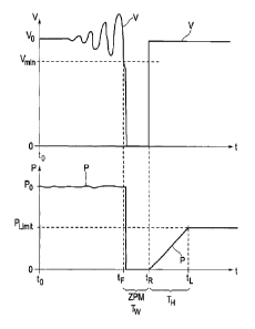
Fig. 10 shows in an upper diagram a schematic view of a voltage course on a
feed point
in relation to the time. The lower diagram correspondingly shows the course of
active
power P fed at the same time. According to this, a voltage V with the value Vo
exists at
the point of time to. Said voltage Vo is a normal voltage, and can, for
example, be the
nominal voltage at the corresponding place. At the same time, a power P is
fed, which
comes very close to the desired value Po, which can be, for example, the
nominal ca-
w pacity of the respective wind power installation, particularly if
sufficient wind is available.
The fed power P can be subject to very limited fluctuations, which is not
important here.
Basically, the underlying wind power installation - a wind park can also be
considered - is
operated in an operating point, where said active power P with a value that
comes close
to Po is fed in.
If there are stability problems, the voltage V can, for example, start to
fluctuate and be-
come instable. Fig. 10 shows in this regard, in the upper diagram, an
oscillation of the
voltage as an example until the voltage V finally falls short of a threshold
value Vmin. This
falling short can, for example, also occur without prior oscillation. At any
rate, the voltage
V falls below said voltage threshold value Vmin at the point of time tF. The
feeding is then
interrupted, and the voltage V falls to the value 0. At the same time, the fed-
in power P
falls to 0.
Now the attempt is made to resume the feeding as quickly as possible. In this
sense, the
feeding is resumed at the point of time tR and the fed-in active power P is
increased as
soon and quickly as possible. Accordingly, the voltage V also increases again
at the point
of time tR. Ideally, as a result of the feeding in of the first active power
P, the voltage V
jumps to the nominal value Vo. Said shown ideal course can, however, also be
different.
To resume the feeding in of active power P as quickly as possible, the wind
power instal-
lation remains connected to the grid, if possible, also directly after the
occurrence of the
fault at the point of time tF, so that in the time from tF to tR, no power P
is fed in, but the
plant remains connected to the grid. Such a condition is here referred to as
zero power
mode (ZPM).
Thus, it is possible to resume the feeding as quickly as possible, and to
increase the fed-
in active power P. However, it is now proposed to increase said fed-in active
power P
CA 02878409 2015-01-06
- 26 -
only to a smaller limited active power PLimit= In this respect, the wind power
installation is
then operated in a limited operating point at the point of time tL. Said
limited operating
point is here shown particularly by a reduced fed-in active power P. The wind
power
installation therefore takes a changed, stabilized operating point, which
particularly has a
higher stability distance, which is also referred to as a stability reserve,
to a stability
boundary. The wind power installation can thus already contribute to a grid
support again,
which is done at the price of a reduced fed-in active power P.
The operating point, which is here basically achieved at the point of time tL,
differs from
the operating point, in which the wind power installation was operated prior
to the point of
time tF, by a changed active power. The operating points can, however, also
additionally
or instead differ according to other parameters, particularly according to the
fed-in reac-
tive power.
The period from point of time tF of the loss of stability to the resumption of
the feeding at
the point of time tR is referred to as resumption time T. Hence, Tw = tR - tF.
The period
from the resumption at the point of time tR until the limited power value is
reached at the
point of time tL is referred to run-up time TH . Therefore, TH = tR.