Note: Descriptions are shown in the official language in which they were submitted.
CA 2878443 2017-05-12
HAND TOOL FOR USE IN THE QUICK DISCONNECTION OF
QUICK CONNECT/DISCONNECT COUPLINGS
Field of the Invention
The invention relates to a hand tool, and more particularly, a hand tool for
use in the quick
disconnect of a quick connect/disconnect coupling.
Background of the Invention
Quick connect/disconnect couplings are commonly used to connect pipes and
tubing in
many fields from automobiles and trucks to waterlines. Although easy to
connect, the
disconnection requires that the release ring on the connector be recessed
simultaneously with
the removal of the conduit in the opposite direction. This can be a problem
when the
connectors are placed in inaccessible areas.
Although many devices have been patented for stripping the ends of electrical
wires,
such as U.S. 4.951,529, to Andre Laurencot; and U.S. 4,475,418 to Isamu Tani
none have
addressed the issue of removing a quick connector from a conduit. U.S.
6,314,629 to Darren
Kady, disclosed a tool for the easy removal of quick disconnect connectors
from conduits
however these tools are unable to handle over five eights (5/8") and above
diameters. Also,
they are unable to handle many of the new slim line style quick
connect/disconnect couplings
for the plumbing industry.
The disclosed hand tool grasps and moves the conduit in the opposite direction
from the
release ring on the connector, easily removing the large connectors from the
conduit.
Page 1
CA 2878443 2017-05-12
SUMMARY OF THE INVENTION
A tool for the removal of connectors from pipes is disclosed that, in one
embodiment,
enables the removal of connectors from large pipes and in another embodiment
from a size range
of pipes. The body of the tool has a body divided into a gripping portion,
having a first and
second end, and a pusher portion, having a first and a second end. A pair of
handles, a first
connected to the second end of the grippingportion and a second to the second
end of the pusher
portion. In some embodiments the second handle, and connected pusher element,
is stationary,
while in others both handles, as well as the pusher and gripper elements, are
movable.
At the first end of the gripping portion is the gripping element which
consists of an arced
movable gripping jaw and an optionally arced stationary gripping jaw. Both the
stationary
gripping jaw and the movable gripping jaw have gripping surfaces that are
parallel to the
circumference of the pipe. The gripping surface of the movable gripping jaw,
and optionally the
stationary gripping jaw, preferably have surfaces that have been roughened by
at least one of
undulations, pointed rows, multiple randomly placed pyramids, pointed columns,
natural or
synthetic coatings. The movable gripping jaw is connected to a linkage,
connecting the jaw to the
first handle.
In some embodiments the gripping portion and pusher portion are connected
through a
pivot connection for rotatability. A spring connected to the handles maintains
the handles at a
maximum separation distance thereby maintaining the first ends of the gripping
portion and
pusher portion adjacent one another.
The pusher portion has at its first end a pusher element that consists of an
arced stationary
pusher jaw and arced movable pusher jaw. Both the stationary pusher jaw and
the movable pusher
jaw have holding surfaces that are flat and parallel to the circumference of
the pipe. The outer face
surface of both the stationary pusher jaw and the movable pusher jaw are on
the same plane in
order to contact the connector ring, or connector, evenly and simultaneously.
The holding surface
of the stationary pusher jaw is on the same plane with the stationary gripper
jaw to prevent angling
of the pipe during connector removal. To facilitate removal of the movable
pusher jaw from the
Page 2
CA 2878443 2017-05-12
pipe, the tip of the pusher jaw is preferably angled with respect to the pipe.
The angle should be
such that the pipe does not catch on the edge of the tip.
The holding surface and the gripping surface have a hardness greater than the
hardness of
said pipe.
To limit the rotation of the movable pusher jaw a stop a-s-tep is used with a
spring being
used between the rotating pusher jaw and the pusher portion to return the
rotating pusher jaw to
a closed position. The connection point between the movable pusher jaw and the
pusher element
1 0 is dimensioned to avoid contact with the connector sealing ring and
ensure even pressure is
applied.
In the tool designed for a range of smaller size pipes, from 1/8 to 3/8, the
arced holding
surface of said movable pusher jaw is dimensioned to have at least 10% of the
arced holding
1 5 surface in contact with the pipe adjacent to the connector. Similarly,
the arced gripping surface
of said movable gripping jaw is dimensioned to have at least 10% of its
gripping surface in
contact with the pipe.
When the handles are initially compressed, the movable pusher jaw and movable
gripper jaw
20 clamp the pipe between the movable jaws and the stationary jaws. Further
compression of the
handles causes the gripping element to move away from the pusher element.
An example linkage is an E plate secured within the gripping portion to slide
upon
compression of the handles. The first end of the E plate receives a gripper
tab at one end of the
25 movable gripper jaw and a second end of said E plate receives a
connector to the first handle. A
guide member, such as a roller or tab, affixed to the gripping portion
prevents the E plate from
twisting.
In the tool that removes connectors from the large pipes, one inch and above,
it is preferable
30 to have a release mechanism on the movable gripper jaw. The release
mechanism interacts with a
release mechanism receiving area to release the movable gripper jaw from a
closed position and
relock the jaw in the closed position. An example release mechanism would
consist of a release
Page 3
CA 2878443 2017-05-12
button, a release block and a spring to maintain the release block in a
position to lock the movable
gripper jaw. Movement of the release button compresses the spring and releases
the movable
gripper jaw to the open position.
On the tool for larger pipes the arced holding surface of the movable pusher
jaw has a
width in the range of about 27mm to about 30.5 mm and preferably in the range
of 28mm to
29.5mm and a depth in the range of about 13.5 mm to about 16.5 mm and
preferably in the range
of 14.5 mm to 15.5 mm. The arced gripping surface of the movable gripping jaw
has a width in
the range of about 20 mm to about 23 mm and preferably in the range of 21.5 mm
to 22.5 mm and
a depth in the range of about 2 mmto about 6 mm and preferably in the range of
about 4 mm. In
this size tool at least 23% of the arced gripping surface of the movable
pusher jaw and the arced
holding surface of the movable gripper jaw contact said pipe.
In some embodiments the gripping portion and the pusher portion can be
connected by a bar
with at least the gripping portion movable along the bar. The tool can further
comprise a bar
connection, the bar connection maintaining the gripping portion and said
pusher portion slidably
connected. In this embodiment at least one of the handles has a compression
member to move
one handle toward the other along the bar connection and a release member to
move the handle
away from the other handle.
In an additional embodiment, the pusher and/or gripper portions have a
receiving area in
the first end that includes a securing member to secure removable pusher
and/or gripper elements.
BRIEF DESCRIPTION OF THE DRAWINGS
The advantages of the instant disclosure will become more apparent when read
with the
specification and the drawings, wherein:
Figure 1 is a front view of the quick release tool in accordance with the
present invention;
Figure 2 is a back view of the quick release tool in accordance with the
present invention;
Figure 3 is a side view of the gripper jaws of the large quick release tool,
in accordance
Page 4
CA 2878443 2017-05-12
with the present invention
Figure 4 is a side view of the pusher jaws of large quick release tool, in
accordance with
the present invention;
Figure 5 is a side view of the large quick release tool with the gripper jaw
in the open
position, in accordance with the present invention;
Figure 6 is a perspective side view of the release tool gripping a pipe and
coupling prior to
separation, in accordance with the present invention;
Figure 7 is a perspective side view of the release tool gripping a pipe and
coupling during
separation, in accordance with the present invention;
Figure 8 is a perspective side view of the gripping portion of the quick
release tool having
ridges for gripping, in accordance with the presentation invention;
Figure 9 is a perspective side view of the gripping portion of the quick
release tool having
teeth for gripping, in accordance with the presentation invention;
Figure 10 is a perspective side view of the movable pusher jaw in accordance
with the
present invention;
Figure 11 is a perspective side view of the gripping portion of the quick
release tool in
accordance with the presentation invention;
Figure 12 is a perspective side view of the movable gripper jaw in accordance
with the
present invention;
Figure 13 is a perspective side view of the interior of the locking mechanism
in accordance
with the present invention;
Figure 14 is a perspective breakaway side view of the quick release tool in
accordance with the present invention;
Page 5
CA 2878443 2017-05-12
Figure 15 is a perspective side view of the E plate in accordance with the
present invention:
Figure 16 is a perspective breakaway side view of the quick release tool
showing the gripper
jaw in the closed position, in accordance with the present invention;
Figure 17 is a perspective breakaway side view of the quick release tool
showing the gripper
jaw in the open position, in accordance with the present invention;
Figure 18 is a breakaway side perspective of the movable gripper jaw placed
within the E
bracket of the tool, in accordance with the present invention;
Figure 19 is a perspective view of the movable pusher jaw in accordance with
the present
invention
Figure 20 is a top breakaway view of the E bracket placed within the tool in
accordance
with the present invention;
Figure 21 is a perspective side view of an alternate embodiment of the tool
incorporating a removable gripper jaw, illustrated without the removable
gripper jaw
accordance with the present invention;
Figure 22 is a perspective side view of the removable jaw to be used with the
tool of Figure
21, in accordance with the present invention;
Figure 23 is a perspective side view of the too of Figure 21 with the
removable jaw inserted
in accordance with the present invention;
Figure 24 is a perspective side view of an alternate removable jaw in
accordance with the
present invention;
Figure 25 is a side view of an alternate embodiment of the tool for use with
mid- sized
pipes in accordance with the present invention;
Page 6
CA 2878443 2017-05-12
Figure 26A is a perspective side view of the pusher section of an alternate
tool have two
moving jaws, in accordance with the invention;
Figure 26B is a perspective side view of the gripper section of an alternate
tool have two
moving jaws, in accordance with the invention;
Figure 27 is a side view of another embodiment of the tool for use with
smaller pipes in
accordance with the present invention;
Figure 28 is a perspective view of the interior of the gripper portion of the
tool in accordance
with the present invention;
Figure 29 is a cutaway perspective view of the interior of the movable pusher
jaw element of
the tool in accordance with the present invention;
Figure 30 is an alternate embodiment of the tool showing the stationary
gripper and pusher
jaws in accordance with the present invention;
Figure 31 is the alternate view of the tool of Figure 30 showing the movable
gripper and
pusher jaws in accordance with the present invention; and
Figure 32 is an alternate embodiment illustrating the pusher jaw having an
extension to
contact recessed rings in accordance with the present invention..
DETAILED DESCRIPTION OF THE INVENTION
The disclosed hand tool is used to remove couplings from tubing, piping or
other conduits.
These quick connect/disconnect couplings are commercially used to connect
tubing in all areas of
industry, where the tubing is for air, chemicals or liquids. The structure,
method of operation, and
methods of connecting to various conduit materials, is well known in the art.
The quick
connect/disconnect coupling maintains the two conduits securely, and in fluid,
and/or air, tight
engagement with one another. The fluid can be a liquid such as water, oil, a
combustion fuel such
as gasoline, or a gas such as air, natural gas, propane, hydraulic fluids or
the like. In the manual
Page 7
CA 2878443 2017-05-12
embodiment, the handle members are hand actuated and through a linkage, such
as described in
the 4,951,529, 4,475,418 and 2,523,936 patents, actuate the gripping and
release members. The
tool can be built on the framework of wire strippers, such as disclosed in
U.S. Patent No.
4,951,529, 4,475,418 or 2,523,936, the disclosures of each patent being
incorporated herein by
reference, as though recited in full.
Definitions
The phrase "maximum separation distance" as used herein means the fully open
position
at which the pair of handles are maintained by some form of spring means. At
the maximum
separation distance the gripping portion first end and the pusher portion
first end are maintained
adjacent to each other.
The term "arc" as used herein refers to the peripheral contour of a component
which is a
part of a circle or other curved line, such as an oval.
The term "spring" as used herein means an elastic contrivance or body, as a
strip or wire of steel
that recovers its shape after being compressed, as for example a leaf spring
and a coil spring.
Quick release couplings are made for easy removal, and have expanded from the
smaller
size hones to larger diameter pipes, such as PVC, Pex, copper and conduits. As
the diameter of
the pipe increases, so does the difficulty in grasping the pipe and releasing
the connector. Further,
these larger couplings are frequently used in tight spaces, such as under
sinks and within large
equipment. The disclosed device enables a user to reach into tight spaces,
grip the tubing, and
separate the coupling with an easy to use hand tool.
The material of manufacture of the gripping tool should be steel or other
durable material
as there is a substantial amount of stress placed on the parts. Of specific
issue is the movable
gripper jaw as the teeth that actually grip the pipe to be removed are formed
from this jaw. In
order to grip the pipe, the material forming teeth and ridges must be harder
that the material being
gripped. The determination of the hardness of the materials needed for
manufacture for use on a
specific material can be through any of the known hardness testing methods.
For example, copper
Page 8
CA 2878443 2017-05-12
pipe will range between 8.0 and 12.0 IIS on the Schore's Scleroscope scale and
can easily be
gripped by any steel used for the tool manufacture. However, if steel pipes
are used, the hardness
of the tool must exceed the hardness of the pipe. In most applications a D2,
heat treated iron alloy
metal, such as an amorphous metal, zinc alloy or stainless steel with the
appropriate heat
treatment process can be used. For materials that are more difficult to grip
and therefore prone to
slippage, such as copper pipes, a hardened steel 440 heat treated to the heat
spec of 50RWC or
equivalent provides optimum results. Further, the greater the tension created
by the compression
spring 112, as noted herein, the faster the contact with the pipe and the
greater the gripping
pressure prior to separating. The choice of the appropriate metal for the end
use will be evident to
those skilled in the art.
In all embodiments herein the surfaces of the jaws contacting the pipe must be
on the same
plane in order for the entire curvature of the jaw to contact the surface of
the pipe with equal
pressure. The washers used on the conduits has a thickness of about 1/16 of an
inch and any
areas of uneven contact between the pipe and the jaw can result in increased
difficulty in
removing the connector or failure to remove pipe from the coupling.
In all designs the arc of movement of the gripper jaws and pusher jaws needs
to be on the same
plane, thereby causing the two stationary jaws and the two movable jaws to
contact the pipe
simultaneously. This is especially important on the tool removing the 'A inch
and the 1 inch pipe,
however the performance of all sized tools can be affected.
The outer and inner surface of the stationary and movable jaws should be on
the same plane
in all embodiments. In other words, the outer surface of the movable gripper
jaw must be flush,
or on the same plane, with the outer surface of the stationary gripper jaw. In
turn the inner surfacc
of the stationary gripper (side with teeth) must be on the same plane with the
inner surface of the
stationary pusher in order not to cause a ratcheting effect of the pipe or
conduit. This ratcheting
effect will cause the pusher to override the release ring of the coupling
resulting in failure to
disconnect. The inner surface of the movable and stationary gripper jaws must
also be flush with
one another, as are the pusher jaws. This enables even pressure on the pipe at
all contact surfaces.
The disclosed tool can be used on 1/8 ¨ 1 inch pipes depending upon the jaw
design. The
Page 9
CA 2878443 2017-05-12
basic body of the tool remains basically and therefore, the body of the tools
will only be described
in Figures 1 and 2 with the jaws and any alternate embodiments being described
individually.
It will be obvious to those skilled in the art that if the body of the tool is
made larger or
smaller, the dimensions of all interacting parts must be resized accordingly.
The primary description herein is the removal of the connectors from the pipe.
However,
the tool can also be used to place pipe into the connector in hard to reach
areas. By simply
reversing the tool the gripper portion moves the pipe to toward the connector
when compressed.
This is extremely valuable when the pipes are in difficult to reach places as
the design of the
handles provides an extension to the user's hand.
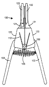
Figure 1 is a front view of the quick release tool 100 while Figure 2
illustrates the back of the
tool 100. The tool 100 includes a pair of handles 102 and 104 that at least
one handle is movable
relative to the other, and are biased by the spring 106, maintaining them in
the spread a part
position during non-use.
The upper section of the tool 100 is divided into a gripping portion 121 and a
pusher
portion 131 and form the upper portion of the frame elements 120 and 130. The
frame elements
120 and 130 are maintained in a rotational relationship with one another
through the use of a
pivot, or hinge, 108.
The gripping portion 121 comprises moveable gripper jaw 122 and stationary
gripper jaw
124. The movement of the moveable gripper jaw 122 must be sufficient to
securely grip the pipe
(not shown), without creating damage, and prevent movement along the length of
the pipe.
The pusher portion 131 carries the movable pusher jaw 132 and stationary
pusher jaw 134.
The movable pusher jaw 132 must securely contact the pipe and ring (as
disclosed hereinafter)
while still enabling the pusher jaws 132 and 134 to move laterally along the
pipe.
The stationary pusher jaw 134 and stationary gripper jaw 124 are affixed to
the pusher
plate 136 and gripper plate 126 respectively that provide support and
structural strength to the
tool 100. Preferably they are affixed through welding or molding, however the
stationary pusher
Page 10
CA 2878443 2017-05-12
jaw 134 and stationary gripper jaw 124 can be affixed to their respective
plates through other
means known in the art such as screws, rivets, etc.
As the handles 102 and 104 are compressed, in what could be referred to as a
first stage,
the movable pusher jaw 132 and movable gripper jaw 122 are closed to grip the
pipe between the
movable gripper jaw 122 and stationary gripper jaw 124 and the movable pusher
jaw 132 and the
stationary pusher jaw 134. The compression spring 112 is tensioned to maintain
the pusher
portion 130 and the gripper portion 120 adjacent one another with the
compression of the spring
112 first translating into the gripping of the jaws as stated above.
Additional compression of the
handles 102 and 104, or a second stage of compression, against the resistive
force of the
compression spring 112, tightly grips the pipe and the pusher portion 130
moves away from the
gripping portion 120, separating the connector from the pipe.
The compression spring 112 provides the pressure that translates to the
functioning of the
gripping portion 120 and the pusher portion 130, with the greater the tension,
the faster the
opening and more powerful the grip. In order to accommodate the larger
diameter pipes, the
tensioning spring 112 should have a minimum gauge of about .05 mm with about 2
mm
maximum. As the tensioning spring 112 affects the strength required to close
the handles 102
and 104, and too great a gauge for the spring would make the tool difficult to
operate.
Although handles are illustrated in conjunction withthe embodiments herein, it
should be
noted that other means for activating the jaws, as well as other handle
designs, can be used.
Additionally, the springs that apply pressure to any portion of the tool can
be replaced with
pneumatics whcn or other device to apply pressure.
In Figures 3 and 4, the 1 inch gripping tool 300 is illustrated, more clearly
showing
relationship between the moveable gripper jaw 334 and stationary gripperjaw
332. In order to
firmly grip the pipe 380, both the movable gripper jaw 334 and stationary
gripper jaw 332 are
provided with a gripping surface 336 and 338. As can be seen in Figure 3, the
stationary
gripper jaw 332 is affixed to the gripper plate 126 that provides the rigidity
and support. The
release button 352 is approximate the movable gripper jaw 334 and serves to
release the
movable gripper jaw 334 from its closed, or storage, position in order to
receive the pipe. The
Page 11
CA 2878443 2017-05-12
release button 352 and its mechanism are described in more detail hereinafter.
The teeth 330 of the stationary gripper jaw 332 must not extend beyond the arc
340 of the
stationary pusher jaw 342. An unevenness between the two causes the stationary
pusher jaw 342
to jump the thin connector ring 384 (Figure 5), thereby either making the
removal of the
connector more difficult or impossible. The variance between the outer most
point of the teeth
338 and the arch 340 has a tolerance of about 1/16 inch, and preferably less.
In these figures the gripping surface 336 is slight rounded. This is one
embodiment of
gripping surface and will work with softer pipe, such as PVC. However, if the
tool is being used
with metal pipe, a sharper surface, such as multiple pyramids or pointed
ridges, such as
illustrated with the stationary gripper jaw 332, ispreferred.
The movable pusher jaw 344 and stationary pusher jaw 342 are also illustrated
with the
stationary pusher jaw 342 attached to, or extending from the pusher plate 136.
The movable
pusher jaw 344 is dimensioned to receive the pipe adjacent the connector. In
order to facilitate
receiving the pipe, the tip 350 of the movable pusher jaw 344 is angled,
thereby preventing the
pipe 380 from catching on the pusher jaw344.
The stationary pusher jaw 342 and the stationary gripper jaw332 are
illustrated herein as
having an arc, however it should be noted that the stationary gripper jaw 332
can be flat, convex
or concave as long as it has a biting point that will grip the pipe that does
not extend beyond the
surface of the stationary pusher jaw 342. As stated heretofore the body of the
tool, handle and
opening mechanism, is described in conjunction with Figures 1 and 2.
In Figure 5 the release button 352 has been moved to release the movable
gripper jaw 334
to receive the pipe 380 (Figures 6 and 7). The movable pusher jaw 344 is
maintained in position
by a spring (as described hereinafter) and will move to receive the pipe 380
upon contact
pressure.
Many connectors 382, especially at the larger diameters, areprovided with a
ring 384
adjacent to the pipe 380 to provide a better seal. This ring 384 must be
contacted with even
Page 12
CA 2878443 2017-05-12
pressure in order enable the removal of the connector382.
In Figure 6 the stationary gripping jaw 334 and stationary pusherjaw 332 (both
not shown)
are placed in contact with the pipe 380, connector 382 and ring 384 that lies
adjacent to the
connector 382. In this in initial position the stationary gripping jaw 332 and
movable gripping
jaw 334 are adjacent to the movable pusher jaw 344 and the stationary pusher
jaw 342. In Figure
7, the user has squeezed the handles 102 and 104, thereby causing the
stationary pusher jaw 342
and movable pusher jaw 344 to move away from the stationary gripper jaw 332
and movable
gripper jaw 334. As the pipe 380 cannot move due to the gripping surface 336,
the pressure being
applied to the connector ring 384 and connector 382, forces the connector 382
and ring 384 off
the end of the pipe.
The release button connector 354 can be seen in this figure extending from the
release
button 352 through the gripper plate 126. The release button 352 mechanism is
described in
detail hereinafter.
In Figure 8 and 9 two example of gripping surfaces are illustrated. In Figure
8 the
movable gripper jaw 834 and stationary gripper jaw 850 each have three ridges
840, 842 and 844
and 850, 852 and 854 respectively. These ridges 840, 842, 844, 850, 852 and
854 can be any
shape that will enable the ridges 840, 842 and 844 to grip and bite into the
pipe. The shape of the
ridges 840, 842 and 844 and 850, 852 and 854 as well as their material of
manufacture will be
determined by the material of the pipe. In Figure 9, the gripping surface 912
of the movable
gripper jaw 910 and gripping surface 920 of the stationary gripper jaw 922
have multiple
diamond or pyramid shaped teeth 914 and 924 respectively. For optimal grip,
the teeth should be
in the range of about .5mm to about 1.25 mm and have a width in the range of
about 5mm to
about 1.25 mm, although the ratios can vary. It is preferred that the teeth
914 and 924 be
alternated in a diamond pattern, staggered along the gripping surface 912 and
920 of the movable
gripper jaw 910 and stationary gripper jaw 922. Alternatively the teeth can be
placed in two or
more columns, generally with a maximum of six (6) teeth in each column. As
with the ridges, the
teeth must be able to firmly grip the surface of the pipe to prevent movement.
Additionally, it
should be noted that the ridges and teeth can be mixed, for example the
stationary gripper jaw can
have ridges while the movable gripper jaw has teeth, or vise versa.
Page 13
CA 2878443 2017-05-12
In some applications, the gripping surface can be a natural or synthetic
substance, for
example rubber, epoxy, or polyurethane, that can prevent the gripper jaws from
slipping on the
pipe. It will be known to those skilled in the art the appropriate gripping
surface based upon the
end use.
In Figure 10, the arc 1000 of the movable gripper jaw 1002 must be such that
at least 10%,
and preferably at least 50%, of the gripping surface 1004 makes contact with
the pipe. To achieve
this, the arc 1000 extends from the proximal point F to the distal point E.
The distance between
proximal point F to the distal point E is about 20 mm to 23 mm and preferably
in the about 21.5 ¨
22.5 mm range. When a line B is drawn between the proximal point F and the
distal point E, the
minimum depth A from line B to the nadir of the arc 1000 is in the range of
about 2 mm to about
6 mm and preferably 4 mm. The placement of the minimum depth A along the arc
1000 is
determined by measuring 14 mm along inset line C from the distal end G of the
gripper jaw 1002
or10. to 11 from distal E to A. The foregoing optimal measurements can be
varied by up to about
50%, but preferably 25% or less as the greater the deviation from preferred
dimensions, the
greater the reduction of reliability.
While it is preferable that the width of the gripping surface 1004 fully
contacts the pipe in
order to provide the appropriate grip on the pipe, it is not necessary. It is
important that a
sufficient portion of the gripping surface 1004 contact the pipe to hold the
pipe surface firmly and
prevent slippage. For optimum gripping, the minimum depth A is the same on
gripper side M as
it is on the opposing gripper side N (not shown). In other words, each side of
the movable gripper
jaw is preferably the same as the opposing side so that both edges between the
gripper side M and
gripper side N and the gripping surface 1004. or arc to side transition
points, contact the surface
of the pipe simultaneously.
To prevent torquing and to obtain the optimal results, the sides of the
movable gripper
jaw, stationary gripper jaw, movable pusher jaw and stationary pusher jaw are,
as described
above.
In most uses, the arc 1000 between distal point E and minimum depth A and
minimum
Page 14
CA 2878443 2017-05-12
depth A and proximal point F will be generally equal. however it is not
necessary that they be
mirror images. In some applications, having distinctly different arcs can be
advantageous and will
be known to those skilled in the art. The arc 1000 preferably has sufficient
contact to enable the
contact surface 1004 to firmly grip thepipe.
In order to ensure that the connectors 382 are removed reliably and to
eliminate damage
to the ring 384, the brace 360 of the movable pusher jaw 344, as illustrated
in Figure 11, has an
arc or cutback area 364 that is dimensioned to clear the ring 384. The arc 370
of the movable
pusher jaw 344 applies an even pressure to the ring 384 in order to facilitate
smooth removal. If
the brace 360 is not cut back a sufficient amount of avoid contact with the
pipe, uneven pressure
will be applied, potentially causing the movable pusher jaw 344 to jump over
the ring 384 and
the connector 382 may not be removed. The brace 360 can be angled or arced to
avoid any
contact the with ring 384 and the design preference would be dependent upon
the manufacturer.
In addition to the movable pusher jaw 344 having an arc 370 that enables at
least 10%, and
preferably at least 50%. of the movable pusher jaw 344 to contact the pipe
while lying adjacent to
the ring 384, the outer face 390 of the movable pusher jaw 344 must be on the
same plane as the
outer face 392 of the stationary pusher jaw 342. If the two faces 390 and 392
are out of
alignment, the ring 384 will be contacted unevenly and the connector 382 may
not be removed.
As with the movable gripper jaw 1002, it is preferable that both the leading
and the
trailing side of the movable pusher jaw 344 contact the pipe simultaneously.
However, the
connector will still be easily removed as long as the outer face 390 contacts
the connector ring
evenly. However, if the inner edge (not illustrated) of the movable pusher jaw
344 contacts the
pipe prior to the outer face 390 contacting the pipe, the outer face will not
contact the connector
ring at the edge and therefore will most likely be unable to remove the
connector.
To apply the required even pressure to the connector ring, the arc 370 of the
moveable
pusher jaw 344 width, between proximal point G and distal point H, is in the
range of about 27
mm to about 30.5 mm and preferably in the range of 28 mm to 29.5 mm with a
depth D in the
range of about 13.5 to about 16.5 and preferably in the range of about 14.5 mm
to about 15.5 mm,
as illustrated in Figure 12. It will be obvious to those skilled in the art
that if the size of the pipe is
Page 15
CA 2878443 2017-05-12
increased or decreased to the point where the arc 370 movable pusher jaw 344
does not contact
the pipe in a manner thatpermits even pressure to be applied to the connector
ring, the arc
dimensions must be altered accordingly. The movable pusher jaw 344, moves back
freely to
receive the pipe, however it is prevented from continuing backward through use
of a pin 902 of
Figure 18.
As illustrated heretofore, a release button 352 is used to release the movable
gripper jaw
334 to enable it to extend around the pipe. The release button 352 is
connected to a shaft 824
that extends through the plate 822 via a slot (not illustrated) to engage the
release block 826 as
illustrated in Figure 13. The release block 826 is engaged with a spring 828
that is, at rest,
pushing the block upward in the locked position. The spring 828 needs to be
dimensioned to
place sufficient pressure on the release block 826 to maintain the locking tab
830 in the movable
gripper jaw receiving notch 840 (Figures 16 and 17). The spring 828 has a
length in the range of
about 7mm to about 12 mm and a diameter of about 1.5 to 3 mm. Once the release
button 352 is
pressed down, the spring 828 is compressed, enabling the locking tab 830 to be
moved from the
notch 840.
The exact dimensions, both length and diameter, as well as the tensile
strength, are
dependent upon the size and type of the pipe being used and will be known to
those skilled in the
art.
In order for the plate 822 to remain solidly attached to the brace plate 860,
only separated by
the depth of the E brace plate 880, a recessed portion 862 of the brace plate
860 is provided with a
depth sufficient to receive the spring 828 and release block 826.
Additionally, a receiving hole
864 is placed in the brace plate 860 to receive the end of the spring 828. It
will be obvious to
those skilled in the art that the depth of the recessed portion 828 must
accommodate the release
block 826 and that varying the depth of the release block 826 will require a
variance in the depth
of the recessed portion 828.
It should be noted that although a spring mechanism is used to release the
movable gripper
jaw, any type of release and relock mechanism can be used and alternate
designs will be known
to those skilled in the art.
Page 16
CA 2878443 2017-05-12
The E plate 880, illustrated within the tool in Figures 14, 18, 20 and 28 and
individually in
Figure 15, is dimensioned to receive the gripper tab 870. The gripper tab 870
fits within the E
plate 880 between the upper extension 884 and the middle extension 886. The
bottom bar
extension 888 is connected to the handle 104 through connector 1730 as
illustrated in Figure 28.
In Figure 20, the connector 1780 is connected to a plate 1782 that is
connected to the bottom bar
extension (not illustrated in Figure 20). As the handles 102 and 104 are
angles, the connection
members 1730 and 1780 would, without a guide, pull the bottom bar extension
888 at an angle. In
order to enable the E plate 880 to be pulled directly down, a guide is
incorporated to place the
connection in direct line with the E plate 880. The placement of the guide
1732 is best seen in
Figures 20and 28. Although only one handle 104 is described herein as moving,
it should be noted
that both handles can move. However, the E plate 880 would continue to
interact with whatever
handle is controlling the movable gripper jaw.
The guide can be a channel, ball bearing, tab or other means to prevent the E
plate 880
from twisting. The connection member 1002 can be a wire or bar and will be
known to those
skilled in the art.
The top bar 882 of the E plate 880 has a length in the range ofabout 10 mm to
17mm,
although the preferred length is about 14 mm. The top bar extension 884, as
well as the mid bar
extension 886 are in the range of about 8 mm to about 12 mm, with a preferred
length of 9mm.
The distance between the top bar extension 884 and the mid bar extension 886
is in the range of
about 8mm to about 18 mm with a preferred distance of about 10 mm. The length
of the spine
889 of the E plate 880 is in the range of about 42 to about 48 preferably 46
mm with the bottom
extension 888 being at least 6mm, and preferably about lOmm. The bottom
extension 888 serves
as the attachment point for the connection between the handles 102 and 104 and
the gripper and
pusher jaws.
To close the movable gripper jaw 889 once the connector has been removed, the
user
squeezes the handles 102 and 104, thereby locking the movable gripper jaw 889
in the
closed position.
Page 17
CA 2878443 2017-05-12
The movable pusher jaw 900, as illustrated in Figure 19, as stated heretofore,
free to rotate
within the pusher portion 130. To prevent the movable pusher jaw 900 from
rotating until it
comes in contact with the body of the pusher portion 130, a stop pin 902 is
used. The stop pin
902 as illustrated contacts a stop within the tool that can be through any
design that will engage
the stop pin 902. In other embodiments, the stop pin 902 could be positioned
so that it contacts a
stop on the outside of the tool. An example of another stop that would be a
lip or ledge on the
movable pusher that would contact the stationary pusher at a certain point and
serve to stop
rotation. Other methods of stopping the movable pusher will be evident to
those skilled in the
mechanical arts. The arc 904 of the movable pusher jaw 900 is, as with the
movable gripper jaw,
a factor in removing the connector. Preferably the arc 904 has a width M, end
to end, of about
14.5 to 15.5 mm and a depth N of about15 mm. The overall length 0 of the
movable pusher
jaw 900 is about 28 to 29.5 mm.
In Figures 21 ¨ 24, the pusher unit 2000 has removable jaws 2030 (Figure 22)
and 2050
(Figure 24). The gripper unit 2020 comprises a movable gripper jaw and a
stationary gripper
jaw as described heretofore. The pusher receiving unit 2000 has a back wall
2008 that is a
continuation of the back wall of the tool. A knob 2006 is located on the
outside of the side plate
2004 and connected to a shaft that extends through the side plate 2004 into
the receiving area
2010. The receiving area 2010 is spaced from the gripper side plate 2014 by
shelf 2012.
The removable jaw 2030 has a rotating jaw 2032 that rotates at pivot 2040 to
separate the
rotating pusher 2034 from the stationary pusher 2036. The stationary pusher
2036 is part of the
stationary base 203g that is configured to fit within the pusher unit 2000.
The periphery of the
removable jaw 2030 should be such that it forms a close fit within the
interior of the receiving
area 2010, shelf 2012 and back wall 2008. The leg 2042 of the removable jaw
2030 should be
dimensioned to be a friction fit within the receiving area 2010 to enable the
shaft to engage force
the leg 2042 tightly against the shelf 2012 when the knob 2006 is tightened.
In this embodiment, stationary pusher 2036 has an extension 2048 and the
rotating pusher
2034 has a mirror extension 2049. The extensions 2048 and 2049 can be
dimensioned fit the
appropriate end use. One examples of use for the aforenoted embodiment would
be to access the
release spring in a fuel filter in designs where the fuel line is locked in
position on the fuel filter
Page 18
CA 2878443 2017-05-12
by a recessed retaining spring. This design is known in the fuel filter art.
Another use would be
to access the recessed release ring connector design as used in Europe. Europe
has two types of
connectors being used, one with prongs along the outer rim and one with the
recessed release ring.
In both designs, releasing the connector requires pressure to be applied to a
recessed portion of the
connection that is readily accessible through use of the disclosed tool.
It should also be noted that the extension can be incorporated on the tool as
described in
figures 1 ¨ 20 and illustrated in Figure 32 wherein the tool 3100 is
illustrated with the movable
gripper jaw 3134 and movable pusher jaw 3142 gripping the pipe 3180. The
extension 3164 is
dimensioned to contact the recessed ring 3184 within the connector 3182.
The removable jaw 2050 is the same design as removable jaw2030, with the
variation being
in the diameter of the extension 2056 of the movable pusher jaw 2052 and
extension 2058 of the
stationary pusher jaw 2054. As with the other embodiments. and described
heretofore, the surfaces
of the pusher jaws must have full, flat surface contact with the line or pipe
and the teeth of the
gripper jaws must not extend beyond the pusher jaws.
As noted above, the embodiments illustrated in Figures 22 ¨ 24 have the
extensions to
access recessed rings, however the removable jaws 2050 and 2030 can be
designed without the
extensions as noted in prior embodiments.
As stated heretofore, the handles and body of the tool can remain the same,
with the jaws
changing. As illustrated in Figure 25 in tool 1500 the pipe removal portion is
comprised of the
movable gripper jaw 1504, stationary gripper jaw 1506, movable pusher jaw 1508
and pusher
stationary jaw (not illustrated). The tool 1500 has the basic construction of
the above described
tool, however, as the arc 1510 is grip pipes between 3/8 to 1/4 inch to remove
the couplings and,
due to the smaller size, the release button is not required. The depth arc
l510 on movable gripper
jaw 1504 is required to enable the single tool to be use on such a large range
of pipe sizes and
should have a depth of about 2mm to about 6 mm, and preferably about 4 nun.
The length of the
arc 1510, distance between R and S. needs to be sufficient to extend on either
side of the largest
pipe within the applicable range of use. For example, in the tool 1500, the
size range of use is
between 3/8 and 3/4 of an inch with the approximate contact between the
movable gripper jaw
Page 19
CA 2878443 2017-05-12
1504 and the pipe being 10% for use with 3/8 inch; 1/2 and 3/4 inch.
The depth dimension on the embodiment in Figure 25 can be varied up to about
30%,
however too much variation negates the ability to handle the larger range of
pipe sizes.
SV
In Figure 27, the smallest of the disclosed embodiments, the tool 1550 again
comprises the
movable gripper jaw 1554, stationary gripper jaw 1556, movable pusher jaw 1558
and stationary
pusher jaw (not illustrated). As seen herein, the arc 1560 of the movable
gripper arm 1554 and arc
1562 of the movable pusher jaw 1558 are much shallower than in prior
embodiments. The tool
1550 is used in conduits having a diameter of between 1/8 and 3/8 inch. The
arc 1560 of the
movable gripper jaw 1554 can have a depth from flat to about 3mm; a depth
greater than 3mm
will prevent the movable gripper jaw 1554 from contacting the 1/8 in pipe. As
discussed with
respect to the arch 1510 must be sufficient to span the largest pipe in the
applicable range of use,
in this embodiment 3/8 inch.
In Figure 28 the interior of the gripper side of the tool 1700 capable of
handling the 1
inch pipe is illustrated. It should be noted that although some elements, such
as the release
mechanism 826 and spring 828, are not required in all sizes, the basic
construction and transfer
of force.
In this figure the movable gripper jaw 334 is in the closed position. As can
be seen, the
spring 828 is pushing the release block 826 upward to maintain the tab 842 in
the tab receiving
notch 840. Upon release of the locking button the movable gripper jaw 334
swings backward
until the tab 870 comes in contact with the top bar extension 884.
As noted heretofore, the E plate 889 used in all size tools is subjected to
force at about a
45 degree angle through connector rod 1730 as the handles are squeezed. Due to
the angle, the
bottom extension 888 of the E plate 889 is pulled outward at the angle
matching that of the
connector rod 1730. This can eventuallybend the E plate 889 and cause the tool
to be
inoperable. In order to prevent the E plate 889 from bending, a guide 1732 is
placed approximate
the base bottom extension 888. As the handles are compressed, pulling the
connector rod 1730
Page 20
CA 2878443 2017-05-12
downward, the E plate 889 is slid downward between the guide 1732 and the back
plate 1712,
thereby prevent the E plate 889 from buckling.
Although the guide 1732 as illustrated in this embodiment is aroller, any
alternate member
can be used to retain the E plate 889. The important feature is for the guide
1732 to be spaced
from the back plate 1712 slightly more than the thickness of the E plate 889.
This prevents any
bending of the E plate 889 as it is fully supported on both sides while still
enabling the E plate 889
to slide. Alternatively a channel can be used in the body to prevent the E
plate from twisting.
Other retaining members and methods will be evident as long as the E plate is
prevented from
twisting while being permitted to slide.
The rotating pusher jaw 1652, as mentioned heretofore, rotates freely in all
embodiments.
As with the E plate described in Figure 28, the rotating pusher jaw 1652
described in Figure 29,
can eliminate some elements in the smaller sizes.
The rotating pusher jaw 1652 has a disc 1660 that extends fromthe interior
surface of the
rotating pusher jaw 1652. Extending from the disc 1660 is a pivot 1658 at
approximately the
center point. At one edge of the disc 1660 is a pusher receiving hole 1656 to
receive the end of the
spring 1672.
In the tool 1650 an arc 1678 is either molded or milled and is dimensioned to
receive the
disc 1660 of the rotating pusher jaw 1652. The back plate 1670 of the tool
1650 contains a
receiving hole 1674 dimensioned to receive the pivot 1658. The spring 1672,
has one end
secured in the spring receiving hole 1676 while the other end is placed in the
pusher receiving
ho1e1656. The spring 1672 is, at rest, maintaining the rotating pusher jaw
1652 in the closed
position. The tension must, however, not be so great as to make it difficult
for the rotating pusher
jaw 1652 to open when placed against the pipe.
To limit the swing of the rotating pusher jaw 1652a stop pin 1654 is
positioned to contact
the body of the tool 1650. The placement of the stop pin 1654 can vary,
depending upon the
size of the tool, and will be known to those skilled in the art.
Alternatively, other types of stops
mechanisms can be used, for example a tab that extends from the bottom of the
pusher jaw to
Page 21
CA 2878443 2017-05-12
interact with the back of the pusher portion, or a tab on the pusher portion
that will prevent
rotation of the movable pusher jaw.
Relative movement between the upper and lower gripping jaws in all embodiments
enables the tool to clamp onto the pipe or conduit, whether one or both jaws
move, or whether
it is the upper or lower jaw that is movable. The movement of either or both
jaws can be
achieved in any of the methods well known in the art.
An example of tools 1600 and 1650 having both jaws moving is illustrated in
Figures 26A
and 26B. In Figure 26A the pusher first jaw 1602 rotates around pivot point
1606 and second
pusher jaw 1604 rotates around pivot 1608, both pivots 1606 and 1608 being
affixed to the body
1620. In Figure 26B the gripper first jaw 1651 rotates around pivot point 1656
and second pusher
jaw 1654 rotates around pivot 1658, both pivots 1656 and 1658 being affixed to
the body 1670.
The dual jaw rotation can be used on either the pusher or gripper or both.
In Figures 30 and 31 an alternate embodiment of a connector release tool 3000
is
illustrated. The tool 3000 is an example of how the body and handles can be
altered. Other
changes to the body design will be evident to those skilled in the art after
reading the disclosed.
Figure 30 illustrates the back of the tool 3000 showing the stationary pusher
jaw 3002 and
stationary gripper jaw 3014. The stationary pusher jaw 3002 is, as was the
prior embodiments,
attached to the pusher body 3004 in a rigid manner. Similarly the stationary
gripper jaw 3014 is
attached to the gripper body 3018. The pusher body 3004 and the gripper body
3018 are separate
units that are connected through the slide bar 3030. The pusher body 3004
remains stationary on
the slide bar 3030 while the gripper body 3018 moves along the slide bar 3030
away the pusher
body 3004 by squeezing the handles 3042 and 3040. The release bar 3032
releases the tension and
enables the gripper body to be moved back toward the pusher body 3004.
In Figure 31, the movable gripper jaw 3016 and the movablepusher jaw 3006 are
seen in the
closed position. The movable pusher jaw 3006 and the movable gripper jaw 3016
are released
from and locked into a closed position through use of slide buttons 3008 and
3020. These buttons
3008 and 3020 have an interior tab that interacts with the movable pusher jaw
3006 and movable
Page 22
CA 2878443 2017-05-12
gripper jaw 3016. Alternatively the movable gripper jaw 3016 can be locked
into placed upon
compression of the handles 3040 and 3042 and released through use of the
release bar3032.
This stationary body on a rod also containing a movable body is known in the
clamp art
and covered under patent nos. 5,009,134, 4,926,722, 5,222,420 and 5,022,137.
The clamps
however have inward facing pads and when the handles are squeezed, the two
pads come
together to make contact. If the portion of the claim is reversed, the
stationary and movable
bodies move apart, however the pad on the movable body is facing away from the
pad on the
stationary body. Therefore internal modification of the design must be made in
order to adapt
the movable gripper. The basic interior design of how the movable body moves
and is locked
in place,however, can be seen in the forgoing patents. Alternate means of
moving and locking
the movable gripper jaw can be used, such as a toothed bar and gears, and will
be known in the
art.
Although the foregoing illustrates represent the preferred embodiments, it
should be noted
that arcs as used in both the release elements and the gripping members are
optional. Any of the
embodiments can use all arced surfaces, all flat surfaces or a combination
thereof It is preferable
that the foregoing gripping members have either teeth, such as pliers, or some
type of non-slide
coating that prevents the conduit from slipping. In some instances, it may be
beneficial to use
both the teeth and a rubber coating and the obvious use of one or the other,
or a combination
thereof will be obvious to those skilled in the art.
It should be noted that although the description of the action of the hand
tool is described as
three specific stages, in actual use the motion is smooth and sufficiently
rapid to eliminate any
separate, specific stages. The mechanism used to translate the movement of the
handles to the
gripping head, as illustrated herein, is an example of one method and
different mechanical
methods of translating the movementof the handles to the movement of the head
will be obvious.
The novelty lies in the gripping and pusher action, rather than how this
action is achieved and the
motion exchange from handles to air tool vvill be obvious to those skilled in
the mechanical arts.
Page 23