Note: Descriptions are shown in the official language in which they were submitted.
CA 02878503 2015-01-06
WO 2014/011497
PCT/1JS2013/049427
SYSTEM AND METHOD FOR CONTROLLING OPERATION OF AN LED-BASED
LIGHT
TECHNICAL FIELD
[0001] The embodiments disclosed herein relate in general to a light
emitting diode
(LED)-based light for replacing a conventional light in a standard light
fixture, and in
particular to a lighting control system for controlling the operation of an
LED-based light.
BACKGROUND
[0002] Fluorescent lights are widely used in a variety of locations, such
as schools and
office buildings. Although conventional fluorescent lights have certain
advantages over, for
example, incandescent lights, they also pose certain disadvantages including,
inter alia,
disposal problems due to the presence of toxic materials within the light.
[0003] LED-based lights designed as one-for-one replacements for
fluorescent lights
have appeared in recent years. LED-based lights can be used in a building with
a control
system capable of managing various aspects of the building, including its
lighting conditions.
A lighting control system can be designed to regulate the lighting conditions
in a building
through selective control of the operation of LED-based lights, in order to,
for example,
improve usability of the building or to optimize its energy use. Some of these
lighting control
systems can remotely regulate individual lighting conditions of multiple
different areas within
the building. Such individualized regulation requires some form of association
between each
LED-based light and the particular area in which the LED-based light is
positioned to
illuminate. Association can entail, for example, manually assigning an LED-
based light
positioned to illuminate a particular area with a logical address designated
within the lighting
control system to correspond to that area. Once associated, the lighting
control system can
correctly control operation of an LED-based light based upon the desired
lighting conditions
for its respective area.
1
SUMMARY
[0004] Disclosed herein are embodiments of methods and systems for
controlling
operation of a light source. In one aspect, a method of associating a light
source with an area
for which the light source is positioned to provide lighting comprises:
identifying, based on a
determined physical position of a light source, one of a plurality of areas as
the area for which
the light source is positioned to provide lighting; identifying at least one
desired lighting
condition for the identified area; and controlling, using a processor,
operation of the light
source based on the identified at least one desired lighting condition for the
identified area.
[0005] In another aspect, a lighting control system comprises: a
light source
positioned to provide lighting for an area; and a control unit configured to:
identify, based on a
determined physical position of the light source, one of a plurality of areas
as the area for
which the light source is positioned to provide lighting, identify at least
one desired lighting
condition for the identified area, and control operation of the light source
based on the
identified at least one desired lighting condition for the identified area.
[0006] In yet another aspect, a method of selecting a lighting
condition for
controlling operation of a light source comprises: storing, in memory, a
plurality of position-
dependent lighting conditions; and selecting, using a processor in
communication with the
memory, one of the position-dependent lighting conditions for controlling
operation of the light
source based on a determined physical position of the light source, such that
the operation of
the light source is controlled based on the selected position-dependent
lighting condition.
[0006a] In yet another aspect, a method of associating a light source
with an area for
which the light source is positioned to provide lighting comprises: receiving,
with a plurality of
spatially distributed communications units, one or more location signals from
the area;
determining a physical position of the light source based on the location
signals; transmitting
the determined physical position of the light source to a processor;
identifying, based on the
determined physical position of the light source, one of a plurality of areas
as the area for
which the light source is positioned to provide lighting; identifying at least
one desired lighting
condition for the identified area; and controlling, using the processor,
operation of the light
source based on the identified at least one desired lighting condition for the
identified area.
[0006b] In yet another aspect, a lighting control system comprises: a
light source
positioned to provide lighting for an area; and a control unit configured to:
identify, based on
2
CA 2878503 2018-07-06
a determined physical position of the light source, one of a plurality of
areas as the area for
which the light source is positioned to provide lighting, identify at least
one desired lighting
condition for the identified area, and control operation of the light source
based on the
identified at least one desired lighting condition for the identified area;
and a plurality of
spatially distributed communications units, the communications units
configured to receive one .
or more location signals from the area, determine the physical position of the
light source
based on the location signals, and transmit the determined physical position
of the light source
to the control unit.
[0006c] In yet another aspect, a method comprises: storing, at a
control unit, data
regarding a plurality of physical areas, the data comprising, for each
physical area: a definition
of the physical area, and an indication of a lighting condition associated
with the physical area;
receiving, at the control unit, a location signal from a first communications
device associated
with a first light source remote from the control unit; determining, at the
control unit, that the
first light source is positioned within a first physical area of the plurality
of physical areas
based on the location signal; storing, at the control unit, an indication of
an association
between the first light source and the first physical area; retrieving, at the
control unit, the
indication of the lighting condition associated with the first physical area;
and operating, using
the control unit, the first light source to satisfy the lighting condition
associated with the first
physical area, wherein operating the first light source comprises transmitting
one or more
command signals to the first communications device associated with the first
light source.
[0007] These and other aspects will be described in additional detail
below.
BRIEF DESCRIPTION OF THE DRAWINGS
[0008] The various features, advantages and other uses of the present
system and
methods will become more apparent by referring to the following detailed
description and
drawings in which:
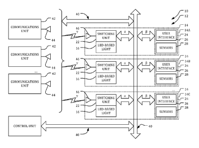
[0009] FIG. 1 is a system view of a lighting control system
configured to control
operation of an LED-based light;
[0010] FIG. 2 is a flow chart illustrating a process including
operations for installing
and associating the LED-based light of FIG. 1 within the lighting control
system;
2a
CA 2878503 2018-07-06
CA 02878503 2015-01-06
WO 2014/011497
PCT/US2013/049427
[0011] FIG. 3 is an exploded perspective view of an example of an LED-based
light
for use in the lighting control system of FIG. 1; and
[0012] FIG. 4 is an exploded perspective view of an alternative example of
an LED-
based light for use in the lighting control system of FIG. 1.
DETAILED DESCRIPTION
[0013] Manual association between an LED-based light and the particular
area in
which the LED-based light is positioned to illuminate can be time consuming
and error-
prone. Further, associations can be broken if a logically addressable LED-
based light is
moved and/or replaced during service, which can cause incorrect control over
the operation of
the LED-based light.
[0014] Disclosed herein are example configurations of a lighting control
system for a
building that can use information relating to the position of an LED-based
light to associate
the LED-based light with a particular area for purposes of regulating the
lighting conditions
for that area. Further disclosed herein are exemplary configurations of a
control system that
can reduce the amount of user input required to determine the information
relating to the
position of the LED-based light.
[0015] A building can include systems for managing various aspects of the
building.
These aspects can generally include the environmental conditions of the
building, such as
heating, ventilation and air conditioning (IIVAC) conditions, security
conditions and/or
lighting conditions, for example. A "smart" building can include a control
system, such as a
building automation system, that can automatically manage the environmental
conditions of
the building in accordance with desired environmental conditions. Such
buildings can
include one or more areas located throughout the building, with each area
lending itself to
individualized regulation of one or more of its environmental conditions.
[0016] A representative building 10 including a building automation system
implementing a lighting control system 12 for regulating the lighting
conditions of multiple
areas 14 throughout the building 10 is shown in FIG. 1. The terms "building"
and "building
automation system" are used herein to describe the lighting control system 12
with reference
to a representative setting in which the lighting control system 12 can be
implemented.
However, the lighting control system 12 could be implemented in other
settings, such as
3
CA 02878503 2015-01-06
WO 2014/011497
PCT/US2013/049427
outdoors, for example, or in other settings in which a number of different
areas 14 lending
themselves to individualized regulation with respect to their lighting
conditions can be
defined.
[0017] Regulation of the environmental conditions of the multiple areas 14
located
throughout the building 10 can include a process of defining the areas 14 to
be controlled.
Each area 14, as it relates to individualized regulation of its environmental
conditions, can
correspond to some characteristic of the building 10 or its contents, or can
correspond to
some characteristic of the defined area 14. With respect to regulation of
lighting conditions
with the lighting control system 12, for example, the area 14 could be defined
as an individual
room or group of rooms located within the building 10. The area 14 could
additionally or
alternatively be defined in terms of its physical surroundings, such as an
area adjacent to
source of light extrinsic to the lighting control system 12, for instance a
window supplying
natural light. The area 14 could also be defined in relation to its particular
functional
considerations and/or constraints with respect to lighting conditions. For
example, the area
14 could be defined above a workstation, or the area 14 could correspond to a
particular type
of room within the building 10, such as an office, a conference room, a
hallway or a
bathroom, for example. Similarly, the area 14 could be defined in relation to
its particular
requirements with respect to lighting conditions, which could involve
requirements of
performance lighting, efficient lighting, safety lighting, comfort lighting
and/or alarm
lighting, for example. As a non-limiting example, an area 14A could be an
individual room
located within the building 10, an area 14B could be located adjacent an east
facing window
receiving natural light and thereby requiring less artificial light from the
lighting control
system 12, and an area 14C could be located adjacent a desk or other
workstation.
[0018] An area 14 could be one discrete individual location within the
building 10, or
could comprise some grouping of locations lending themselves to similar
regulation of their
environmental conditions. A building 10 could include a single area 14 or
multiple areas 14,
and each area 14 of a building 10 need not be defined according to an approach
used to define
another area 14 of the building 10. The building 10 can include more or less
than the
illustrated areas 14A, 14B and 14C, and the building 10 can include
alternative and/or
additional areas 14 depending upon which of a variety of environmental
conditions is
regulated. That is, with respect to regulation of environmental conditions
other than lighting
4
CA 02878503 2015-01-06
WO 2014/011497
PCT/US2013/049427
conditions, areas 14 could be defined within the building 10 other than as the
areas 14A, 14B
and 14C described above, and alternative and/or additional areas 14 could be
defined for
purposes of individualized regulation of the various other environmental
conditions.
[0019] A building automation system for the building 10 can implement the
lighting
control system 12 to individually regulate the lighting conditions for each of
the areas 14
located throughout the building 10. The illustrated lighting control system 12
may include
one or more LED-based lights 16 positioned to illuminate each of the areas.
The lighting
conditions for the area 14 in which an LED-based light 16 is positioned can be
regulated
through selective control of the operation the LED-based light 16. For ease of
understanding,
the lighting control system 12 is generally described below with reference to
a single LED-
based light 16 positioned to illuminate a singular area 14. However, it should
be understood
that the lighting control system 12 can include a plurality of areas 14A, 14B
and 14C, each of
which can include one or more respective LED-based lights 16 positioned to
illuminate the
areas 14A, 14B and 14C.
[0020] The lighting control system 12 includes one or more devices for
controlling
the operation of the LED-based light 16. In a basic lighting system, operation
of an LED-
based light 16 could be controlled by electrically connecting a device such as
a light switch,
dimmer or other similar operator actuated device between the LED-based light
16 and a
power supply. These devices control operation of the LED-based light 16 by
regulating a
supply of AC or DC electrical power to the LED-based light 16. For example, a
supply of
electrical power to the LED-based light 16 can be selectively switched to
control an on/off
function of the LED-based light 16, and a supply of electrical power to the
LED-based light
16 can be selectively modulated to control a dimming function of the LED-based
light 16.
[0021] The illustrated implementation of the lighting control system 12
includes a
control unit 20 configured to control the operation of the LED-based light 16
by selectively
controlling a supply of electrical power to the LED-based light 16. The
control unit 20 can be
or include one or more controllers configured for controlling the operation of
multiple LED-
based lights 16 positioned in different areas 14 located throughout the
building 10. A
controller could be a programmable controller, such as a microcomputer
including a random
access memory (RAM), a read-only memory (ROM) and a central processing unit
(CPU) in
addition to various input and output connections. Generally, the control
functions described
CA 02878503 2015-01-06
WO 2014/011497
PCT/US2013/049427
herein can he implemented by one or more software programs stored in internal
or external
memory and are performed by execution by the CPU. however, some or all of the
functions
could also be implemented by hardware components. Although the control unit 20
is shown
and described as a single central controller for performing multiple functions
related to
multiple areas 14, the functions described herein could be implemented by
separate
controllers which collectively comprise the illustrated control unit 20.
[0022] The control unit 20 can be electrically connected between the LED-
based light
16 and a power supply and configured to control operation of the LED-based
light 16 by
directly switching and/or modulating a supply of electrical power to LED-based
light 16.
Alternatively, the control unit 20 can be configured to control operation of
the LED-based
light 16 by indirectly controlling a supply of electrical power to the LED-
based light 16, for
example by communicating a control signal a to a switching device. For
example, as shown
in FIG. 1, lighting control system 12 may include a switching unit 22
communicatively
coupled to the control unit 20.
[0023] The switching unit 22 is electrically connected between the LED-
based light
16 and a power supply and is configured to receive the control signal a and,
in response to the
control signal a, selectively regulate a supply of electrical power to the LED-
based light 16.
The switching unit 22 can control an on/off function of the LED-based light 16
by including a
relay or other mechanical, electrical or electromechanical switch configured
to selectively
switch a supply of electrical power to the LED-based light 16. The switching
unit 22 can
alternatively or additionally be or include components configured to
selectively modulate a
supply of electrical power to the LED-based light 16 to control a dimming
function of the
LED-based light 16. The switching unit 22 can selectively regulate a supply of
electrical
power to the LED-based light 16 to control operation of the LED-based light 16
in a variety
of other manners. For example, in addition to controlling on/off and dimming
functions of
the LED-based light 16, the switching unit 22 can also be configured to
regulate a supply of
electrical power to the LED-based light 16 to achieve continuous, intermittent
or other non-
continuous operation of the LED-based light 16. For example, the LED-based
light 16 could
be operated steadily, variably, or could be blinked, flashed or amplified
according to some
timed pattern by the switching unit 22, depending upon the desired lighting
conditions for the
area 14 in which the LED-based light 16 is positioned to illuminate.
6
CA 02878503 2015-01-06
WO 2014/011497
PCT/US2013/049427
[0024] Each area 14 located throughout the building 10 can lend itself to
individualized regulation of its lighting conditions in accordance with
respective desired
lighting conditions. The lighting control system 12 includes the control unit
20 for
controlling the lighting conditions of the area 14 through selective control
of the operation of
the LED-based light 16 positioned to illuminate the area 14. As described
above, the control
unit 20 controls the operation of the LED-based light 16 by communicating a
control signal a
to the switching unit 22 configured to selectively regulate a supply of
electrical power to the
LED-based light 16. The control signal a generally corresponds to the desired
lighting
conditions for the area 14 in which the LED-based light 16 is positioned to
illuminate. The
control signal a can be representative of a setpoint illumination level for
the area 14, or could
be representative of some other particular requirement or characteristic with
respect to the
desired lighting conditions for the area 14 in which the LED-based light 16 is
positioned to
illuminate. For example, the control signal a could be representative of a
requirement for
performance lighting, efficient lighting, safety lighting, comfort lighting
and/or alarm lighting
in the area 14.
[0025] The control unit 20 is configured to determine the desired lighting
conditions
for the area 14 in which the LED-based light 16 is positioned to illuminate,
and to generate
the control signal a corresponding to the desired lighting conditions. The
control unit 20 can
generate the control signal a with logic implementing various algorithmic or
heuristics
techniques. As non-limiting examples, the control unit 20 can include logic
implementing
timers, alarms, and/or rules relating to occupancy sensing, daylight
harvesting or manual
override control.
[0026] The lighting control system 12 can further include one or more input
devices
24 corresponding to each of the areas 14. The input devices 24 are configured
to relay
information relating to the actual or desired lighting conditions and/or other
environmental
conditions of the area 14 to the control unit 20. The lighting control system
12 can utilize the
information from an input device 24 for purposes of individualized regulation
of the lighting
conditions for its area 14. The input devices 24 are configured to generate
one or more input
signals [3. The input devices 24 are communicatively coupled to the control
unit 20, and the
logic of the control unit 20 can be responsive to the input signals 13 to
generate the control
signal a for communication to the switching unit 22.
7
CA 02878503 2015-01-06
WO 2014/011497
PCT/US2013/049427
[0027] The illustrated input devices 24 can include a user interface 26 and
various
sensors 28. The user interface 26 is configured to receive information from a
user of the
building 10 relating to requested lighting conditions for the area 14 to which
the user interface
26 corresponds, and to generate corresponding input signals 13 for
communication to the
control unit 20. The user interface 26 can be or include a switch, dimmer or
other user
actuated device. The user interface 26 could also include a web-based or
similar computer-
based component for receiving information relating to requested lighting
conditions for an
area 14.
[0028] The lighting control system 12 can incorporate the input signals 13
communicated from the user interface 26 to varying degrees as compared to
input signals 13
communicated from other input devices 24. For example, the lighting control
system 12
could give priority to the user interface 26 by providing for manual override
control of the
operation of the LED-based light 16 on the basis of a user's actuation of the
user interface 26.
In this example, the control unit 20 could include logic for generating a
control signal a
directing the switching unit 22 to regulate a supply of electrical power to
the LED-based light
16 in direct accordance with an operator's requested lighting conditions.
Alternatively, the
lighting control system 12 could be arranged such that a supply of electrical
power to LED-
based light 16 is regulated directly by the user interface 26 in accordance
with an operator's
requested lighting conditions without regard to a control signal a generated
by the control unit
20.
[0029] The sensors 28 may be configured for measuring, monitoring and/or
estimating various environmental conditions within a corresponding area 14 and
for
generating corresponding input signals 13 for communication to the control
unit 20. Sensors
28 can include, for example, a sensor for measuring the actual lighting
conditions of the area
14, or sensors 28 could include a sensor for monitoring or estimating
occupancy of the area
14. The sensors 28 could include a motion sensor, a voice-activated sensor or
a clock or
calendar, for example. Similar to the input signals 13 from the user interface
26, the input
signals p fmm the sensors 28 can be incorporated into the logic of the control
unit 20 for
generation of the control signal a.
[0030] An exemplary communications link 40 is included in the lighting
control
system 12 for communicatively coupling the components of the lighting control
system 12.
8
CA 02878503 2015-01-06
WO 2014/011497
PCT/US2013/049427
The communications link 40 may generally be configured to support digital
and/or analog
communication between the components included in the lighting control system
12. For
example, the communications link 40 may be configured to communicatively
couple the
control unit 20, the switching unit 22 and the input devices 24. The
communications link 40
can include wired and/or wireless communications channels using any industry
standard or
proprietary protocols. As a non-limiting example, a wired communications link
40 could be
implemented with 0-10V signals, DALI or Ethernet. As a further non-limiting
example, a
wireless coimmunications link 40 could be implemented, for example, with
wireless DALI,
IEEE 802.11, Wi-Fi, Bluetooth or RF channels, or through infrared, ultrasonic
or 'modulated
visible light, such as light emitted from the LED-based lights 16. Further,
the
communications link 40 could be implemented with multiple communications
channels, each
using differing protocols.
[0031] The illustrated lighting control system 12 can provide localized
regulation of
the lighting conditions for multiple different areas 14 with the control unit
20 by selectively
controlling the operation of the respective LED-based lights 16 positioned to
illuminate the
respective areas 14. The control unit 20 can determine differing desired
lighting conditions
for each of the areas 14. For example, the desired lighting conditions for
area 14A could
necessitate that the LED-based light 16 positioned to illuminate area 14A be
controlled to an
on state, the desired lighting conditions for area 14B could necessitate that
the LED-based
light 16 positioned to illuminate area 14B be controlled to an off state, and
the desired
lighting conditions for area 14C could necessitate that the LED-based light 16
positioned to
illuminate area 14C be controlled to a modulated state.
[0032] In order for the lighting control system 12 to efficiently regulate
the lighting
conditions in multiple areas 14, the lighting control system 12 may be
configured to control
the LED-based light 16 positioned to illuminate a particular area 14 without
affecting the
operation of LED-based lights 16 positioned to illuminate other areas 14.
Proper functioning
of the lighting control system 12 generally requires some association between
each LED-
based light 16 and the area 14 in which the LED-based light 16 is positioned
to illuminate.
Association can entail, for example, manually landing wires between terminals
of the control
unit 20 and switching units 22 and/or corresponding LED-based lights 16.
Alternatively,
association could entail manually assigning a switching unit 22 and/or
corresponding LED-
9
CA 02878503 2015-01-06
WO 2014/011497
PCT/US2013/049427
based light 16 with a logical address designated within the lighting control
system 12, for
example within the logic of the control unit 20, to correspond to a particular
area 14. Once
associated, the lighting control system 12 can control operation of an LED-
based light 16 to
regulate the lighting conditions for its respective area 14 according to its
desired lighting
conditions.
[0033] The illustrated lighting control system 12 may include a plurality
of
communications units 42 configured to receive information relating to the
position of an
LED-based light 16 within the building 10. The lighting control system 12 is
configured to
use the information relating to the position of the LED-based light 16 within
the building 10
to associate the LED-based light 16 with the area 14 in which the LED-based
light 16 is
positioned to illuminate. For example, the lighting control system 12 can be
configured to
compare the position of an LED-based light 16 with known or deteimined
positions of the
areas 14 located throughout the building 10. The lighting control system 12
can then
correlate the position of the LED-based light 16 with a particular area 14 in
which the LED-
based light 16 is positioned to illuminate. Once a correlation is drawn
between a particular
LED-based light 16 and the area 14 in which the LED-based light 16 is
positioned to
illuminate, the lighting control system 12 can associate the LED-based light
16 to the area 14
for purposes of future regulation of the lighting conditions for that area 14.
[0034] The communications units 42 may be communicatively coupled to the
lighting
control system 12 through one or more communications channels that can be
included in the
communications link 40. As shown in FIG. 1, the communications units 42 may be
communicatively coupled to the switching units 22. Each of the communications
units 42
may include a communications device 44 configured to receive a location signal
7 from a
communications device 46 included in the switching units 22. The
communications devices
44 and 46 can be configured for communication through a communications channel
implemented to communicatively couple the communications units 42 and the
switching units
22, and the communications channel need not be the same as used elsewhere in
the
communication link 40. For example, an existing building automation system for
the
building 10 may already include wired communications channels for
communicatively
coupling the control unit 20, the switching unit 22 and the input devices 24.
The building
automation system for the building 10 could be retrofitted to implement the
lighting control
CA 02878503 2015-01-06
WO 2014/011497
PCT/US2013/049427
system 12 by including a wireless communications channel configured to
communicatively
couple the communications units 42 to the switching units 22. In this non-
limiting example,
the communications devices 44 and 46 can be the illustrated transceivers 44
and 46.
However, the communications devices 44 and 46 could be other devices known to
those
skilled in the art configured to send and/or receive the location signal 7
over a chosen
communications channel included in the communications link 40.
[0035] As shown in FIG. 1, the communications units 42 may be
communicatively
coupled to switching units 22 to receive the location signal 7 from the
communications
devices 46. The switching units 22 including the communications devices 46 can
be located
adjacent to or included in corresponding LED-based lights 16, such that the
location signal 7
conveys information generally relating to the position of the LED-based light
16. Although
the communications devices 46 are described with reference to the switching
units 22, the
communications devices 46 could alternatively be included in the LED-based
lights 16, or
could be otherwise included in the lighting control system 12 according to
some known or
determinable spatial relationship with the LED-based light 16.
[0036] The lighting control system 12 is configured to determine, or
estimate, the
physical position of each of the LED-based lights 16 based at least partially
upon the location
signal 7. The position of an LED-based light 16 could be determined
absolutely, for example,
or could be detelmined relative to some aspect relating to the building 10 or
lighting control
system 12. In the exemplary implementation of the lighting control system 12,
multiple
communications units 42 form a spatially distributed network of communications
units 42.
The communications units 42 can be distributed within and/or without the
building 10 to
form the spatially distributed network of communications units 42. The
location signal 7 can
be received by one or more of the communications units 42, which can be
configured to
determine the position of the LED-based lights 16, either individually, in
some combination
with each other, and/or in combination with the control unit 20 or other
components of the
lighting control system 12.
[0037] The lighting control system 12 can be configured to determine the
position of
the LED-based light 16 using various techniques, either individually or in
some combination.
As non-limiting examples, the position of an LED-based light 16 can be
determined based
upon time of arrival (TOA) of RF, infrared or ultrasonic signals, or based
upon TOA of light
11
CA 02878503 2015-01-06
WO 2014/011497
PCT/US2013/049427
signals, such as visible light signals emitted from the LED-based lights 16;
the position of an
LED-based light 16 can be determined based upon direction finding (DU) of RF,
infrared or
ultrasonic signals, or based upon DF of light signals, such as visible light
signals emitted
from the LED-based lights 16; the position of an LED-based light 16 could be
determined by
superimposing currents on power lines foliating a power grid, or though other
branch circuit
monitoring methods; or the position of an LED-based light 16 could be
determined by
monitoring the strength of the location signal 7 throughout the spatially
distributed network of
communications units 42. The position of an LED-based light 16 could also be
determined
through communication with components external from the lighting control
system 12, for
example by using 3g or 4g signals to communicate with global positioning
systems (GPSs) or
other external location systems. The position of the LED-based light 16 could
also be
determined more accurately through some combination of the above techniques.
[0038] A process of installing an LED-based light 16 into the lighting
control system
12 of a building 10 is illustrated in FIG. 2. In step S10, information
relating to the positions
of each of the areas 14 located throughout the building 10 is stored in the
lighting control
system 12. The lighting control system 12 can be configured to know or
determine the
positions of each of the areas 14. Similar to the positions of the LED-based
lights 16, the
positions of the areas 14 could be known or determined absolutely, for
example, or relative to
some aspect relating to the building 10 or the lighting control system 12. For
example, the
physical aspects of the building 10, such as floor plans or power supply
structures, could be
stored in memory on the control unit 20, along with information relating to
the relative
positions of the areas 14 within the building 10.
[0039] In step S12, an LED-based light 16 is installed into the lighting
control system
12. In step S14, the LED-based light 16 joins the lighting control system 12
by
communicating with the control unit 20 through the communications link 40, and
in step S16,
the control unit 20 recognizes the LED-based light 16 as newly installed into
(or newly
positioned within) the lighting control system 12. The LED-based light 16 can
have a logical
address readable by the control unit 20, for example, or can be otherwise
recognizable by the
control unit 20 as a distinct lighting element.
[0040] In step S18, the location signal y is communicated to the spatially
distributed
network of communications units 42. The location signal y can be communicated
12
CA 02878503 2015-01-06
WO 2014/011497
PCT/US2013/049427
autonomously, for example, or at the direction of the installer or at the
direction of the
lighting control system 12 or control unit 20. In step S20, the position of
the LED-based light
16 is determined using one or more of the above described location techniques,
as well as
others. The logic for determining the position of the LED-based light 16 can
be implemented
by one or more of the communications units 42, or can be distributed between
one or more of
the communications units 42 and the other components of the lighting control
system 12. The
position of an LED-based light 16 could also be determined physically
externally from the
lighting control system 12, for example through communication with a GPS or
other location
system. The position of the newly installed LED-based 16 could also be
determined and/or
verified with reference to one or more LED-based lights 16 whose positions are
manually
determined.
[0041] In step S22, the lighting control system 12 can use the determined
position of
the LED-based light 16 to associate the LED-based light 16 with the area 14 in
which the
LED-based light 16 is positioned to illuminate. For example, the lighting
control system 12
can implement logic using the control unit 20 to compare the determined
position of the
LED-based light 16 with the known or determined positions of the areas 14
located
throughout the building 10. By correlating the determined position of the LED-
based light 16
with a position of a particular area 14, the control unit 20 can determine
that the LED-based
light 16 is positioned to illuminate that particular area 14. Finally, in step
S24, the lighting
control system 12 can associate the LED-based light 16 to the area 14 within
the control unit
20 for purposes of future regulation of the lighting conditions for that area
14.
[0042] FIG. 3 illustrates an example of an LED-based light 116 for use in
the lighting
control system 12. The LED-based light 116 is configured to replace a
conventional light in a
standard light fixture 110. The light fixture 110 can be designed to accept
conventional
fluorescent lights, such as T5, T8 or T12 fluorescent tube lights, or can be
designed to accept
other standard lights, such as incandescent bulbs. The light fixture 110 could
alternatively be
designed to accept non-standard lights, such as lights installed by an
electrician. The light
fixture 110 can connect to a power supply, and can optionally include a
ballast connected
between the power supply and the LED-based light 116. The switching unit 22
could be
compatible with the fixture 110 to electrically connect between the power
supply and the
LED-based light 116, or the switching unit 22 could be included in the fixture
110, for
13
CA 02878503 2015-01-06
WO 2014/011497
PCT/US2013/049427
example.
[0043] In some implementations, the LED-based light 116 includes a housing
112 at
least partially defined by a high dielectric light transmitting lens 114. The
lens 114 can be
made from polycarbonate, acrylic, glass or other light transmitting material
(i.e., the lens 114
can be transparent or translucent). The term "lens" as used herein means a
light transmitting
structure, and not necessarily a structure for concentrating or diverging
light. The LED-based
light 116 can include features for uniforinly distributing light to an
environment to be
illuminated in order to replicate the uniform light distribution of a
conventional fluorescent
light. For example, the lens 114 can be manufactured to include light
diffracting structures,
such as ridges, dots, bumps, dimples or other uneven surfaces formed on an
interior or
exterior of the lens 114. The light diffracting structures can be formed
integrally with the lens
114, for example, by molding or extruding, or the structures can be formed in
a separate
manufacturing step such as surface roughening. In addition to or as an
alternative to light
diffracting structures, a light diffracting film can be applied to the
exterior of the lens 114 or
placed in the housing 112, or, the material from which the lens 114 is formed
can include
light refracting particles. For example, the lens 114 can be made from a
composite, such as
polycarbonate, with particles of a light refracting material interspersed in
the polycarbonate.
In other embodiments, the LED-based light 116 may not include any light
diffracting
structures or film.
[0044] The housing 112 can include a light transmitting tube at least
partially defined
by the lens 114. Alternatively, the housing 112 can be formed by attaching
multiple
individual parts, not all of which need be light transmitting. For example,
the housing 112
can be formed in part by attaching the lens 114 to an opaque lower portion.
The housing 112
can additionally include other components, such as one or more highly
thermally conductive
structures for enhancing heat dissipation. While the illustrated housing 112
is cylindrical, a
housing having a square, triangular, polygonal, or other cross sectional shape
can alternatively
be used. Similarly, while the illustrated housing 112 is linear, housings
having an alternative
shape, e.g., a LT-shape or a circular shape can alternatively he used. The LED-
based light 116
can have any suitable length. For example, the LED-based light 116 may be
approximately
48" long, and the housing 112 can have a 0.625", 1.0" or 1.5" diameter for
engagement with a
common standard fluorescent light fixture.
14
CA 02878503 2015-01-06
WO 2014/011497
PCT/US2013/049427
[0045] The LED-based light 116 can include an electrical connector 118
positioned at
each end of the housing 112. In the illustrated example, the electrical
connector 118 is a bi-
pin connector carried by an end cap 120. A pair of end caps 120 can be
attached at opposing
longitudinal ends of the housing 112 for physically connecting the LED-based
light 116 to a
standard fluorescent light fixture 110. The end caps 120 can be the sole
physical connection
between the LED-based light 116 and the fixture 110. At least one of the end
caps 120 can
additionally electrically connect the LED-based light 116 to the fixture 110
to provide power
to the LED-based light 116. Each end cap 120 can include two pins 122,
although two of the
total four pins can be "dummy pins" that provide physical but not electrical
connection to the
fixture 110. Bi-pin electrical connector 118 is compatible with many standard
fluorescent
fixtures, although other types of electrical connectors can be used, such as
single pin
connector or screw type connector.
[0046] The LED-based light 116 can include a circuit board 124 supported
within the
housing 112. The circuit board 124 can include at least one LED 126, a
plurality of series-
connected or parallel-connected LEDs 126, an array of LEDs 126 or any other
arrangement of
LEDs 126. Each of the illustrated LEDs 126 can include a single diode or
multiple diodes,
such as a package of diodes producing light that appears to an ordinary
observer as coming
from a single source. The LEDs 126 can be surface-mount devices of a type
available from
Nichia, although other types of LEDs can alternatively be used. For example,
the LED-based
light 116 can include high-brightness semiconductor LEDs, organic light
emitting diodes
(OLEDs), semiconductor dies that produce light in response to current, light
emitting
polymers, electro-luminescent strips (EL) or the like.
[0047] The circuit board 124 can include power supply circuitry configured
to
condition an input power received from, for example, the fixture 110 through
the electrical
connector 118 to a power usable by and suitable for the LEDs 126. In some
implementations,
the power supply circuitry can include one or more of an inrush protection
circuit, a surge
suppressor circuit, a noise filter circuit, a rectifier circuit, a main filter
circuit, a current
regulator circuit and a shunt voltage regulator circuit. The power supply
circuitry can be
suitably designed to receive a wide range of currents and/or voltages from a
power source and
convert them to a power usable by the LEDs 126.
[0048] The circuit board 124 is illustrated as an elongate printed circuit
board. The
CA 02878503 2015-01-06
WO 2014/011497
PCT/US2013/049427
circuit board 124 can extend a length or a partial length of the housing 112.
Multiple circuit
board sections can be joined by bridge connectors to create the circuit board
124. The circuit
board 124 can be supported within the housing 112 through slidable engagement
with a part
of the housing 112, though the circuit board 124 can alternatively be clipped,
adhered, snap-
or friction-fit, screwed or otherwise connected to the housing 112. Also,
other types of circuit
boards may be used, such as a metal core circuit board. Or, instead of the
circuit board 124,
other types of electrical connections (e.g., wires) can be used to
electrically connect the LEDs
126 to a power source.
[0049] The LEDs 126 can emit white light or light within a range of
wavelengths.
However, LEDs that emit blue light, ultra-violet light or other wavelengths of
light can be
used in place of or in combination with white light emitting LEDs 126. The
number, spacing
and orientation of the LEDs 126 can be a function of a length of the LED-based
light 116, a
desired lumen output of the LED-based light 116, the wattage of the LEDs 126
and/or the
viewing angle of the LEDs 126. For a 48" LED-based light 116, the number of
LEDs 126
may vary from about thirty to sixty such that the LED-based light 116 outputs
approximately
3,000 lumens. However, a different number of LEDs 126 can alternatively be
used, and the
LED-based light 116 can output any other amount of lumens. The LEDs 126 can be
evenly
spaced along the circuit board 124 and arranged on the circuit board 124 to
substantially fill a
space along a length of the lens 114 between end caps 120 positioned at
opposing
longitudinal ends of the housing 112. Alternatively, single or multiple LEDs
126 can be
located at one or both ends of the LED-based light 116. The LEDs 126 can be
arranged in a
single longitudinally extending row along a central portion of the LED circuit
board 124, as
shown, or can be arranged in a plurality of rows or arranged in groups. The
spacing of the
LEDs 126 can be determined based on, for example, the light distribution of
each LED 126
and the number of LEDs 126.
[0050] An alternative example of and LED-based light 216 is shown in FIG.
4. The
construction of the LED-based light 216 can be similar to the construction of
the LED-based
light 116 of FIG. 3, and the LED-based light 216 can include the housing 112,
the lens 114,
the hi-pin 122 electrical connectors 118 carried by a pair of end caps 120,
the circuit board
124 and the LEDs 126.
[0051] In addition, the LED-based light 216 can incorporate one or more of
the above
16
CA 02878503 2015-01-06
WO 2014/011497
PCT/US2013/049427
described components of the lighting control system 12. For example, the
switching unit 22
can be included the LED-based light 216. The switching unit 22 can be included
in the
circuit board 124 and can be electrically connected between the fixture 110
conveying
electrical power from a power supply and the LEDs 126 of the LED-based light
216. The
switching unit 22 of the LED-based light 216 can be configured to receive the
control signal a
and, in response to the control signal a, selectively regulate a supply of
electrical power to the
LEDs 126 to control operation of the LED-based light 216.
[0052] The LED-based light 216 can also incorporate one or more of the
sensors 28,
for example, and can incorporate a communications unit 42 for determining the
location of
other LED-based lights 216. For example, multiple LED-based lights 216
including a
communications unit 42 can together form the spatially distributed network of
communications units 42. The positions of one or more LED-based lights 216
including a
communications unit 42 can be determined manually, with the positions of the
remainder of
the LED-based lights 16, 116 or 216 installed into the lighting control system
12 being
determined according to the process and techniques described above. In this
example, the
LED-based light 216 also includes communications devices 44 and/or 46 for
sending and
receiving location signals 7, although the LED-based light 216 could also
communicate with
the lighting control system 12 through the communications channels of the
communications
link 40.
[0053] The LED-based lights described herein are presented as examples and
are not
meant to be limiting. The embodiments can be used with any lighting components
known to
those skilled in the art and compatible with the scope of the disclosure. In
addition, the
disclosed processes and techniques can be applied in a variety of building
automation system
implemented control systems to regulate environmental conditions other than
lighting
conditions. For example, the disclosed processes and techniques can be applied
to determine
the position of printers, alatm system components and/or HVAC components, and
various
controllers can be control operation of these components for purpose of
regulating related
environmental conditions of the building 10.
[0054] The following are examples of embodiments disclosed herein. In one
embodiment, a method of associating a light source with an area for which the
light source is
positioned to provide lighting, comprises: identifying, based on a determined
physical
17
CA 02878503 2015-01-06
WO 2014/011497
PCT/US2013/049427
position of a light source, one of a plurality of areas as the area for which
the light source is
positioned to provide lighting; identifying at least one desired lighting
condition for the
identified area; and controlling, using a processor, operation of the light
source based on the
identified at least one desired lighting condition for the identified area.
[0055] In one aspect of this embodiment, the method further comprises:
comparing
the determined physical position of the light source against known physical
positions of the
plurality of areas to identify the area for which the light source is
positioned to provide
lighting.
[0056] In another aspect of this embodiment, the method further comprises:
receiving
information indicative of the physical position of the light source; and
determining the
physical position of the light source based on the infoimation.
[0057] In another aspect of this embodiment, the method further comprises:
receiving
the determined physical position of the light source.
[0058] In another aspect of this embodiment, the light source is an LED-
based
replacement for a fluorescent light.
[0059] In another embodiment, a lighting control system, comprises: a light
source
positioned to provide lighting for an area; and a control unit configured to:
identify, based on
a determined physical position of the light source, one of a plurality of
areas as the area for
which the light source is positioned to provide lighting, identify at least
one desired lighting
condition for the identified area, and control operation of the light source
based on the
identified at least one desired lighting condition for the identified area.
[0060] In one aspect of this embodiment, the control unit is further
configured to:
compare the deteimined physical position of the light source against known
physical positions
of the plurality of areas to identify the area for which the light source is
positioned to provide
lighting.
[0061] In one aspect of this embodiment, the control unit is further
configured to:
receive information indicative of the physical position of the light source,
and determine the
physical position of the light source based on the information.
[0062] In another aspect of this embodiment, the control unit is further
configured to:
receive the determined physical position of the light source.
[0063] In another aspect of this embodiment, the lighting control system
further
18
CA 02878503 2015-01-06
WO 2014/011497
PCT/US2013/049427
comprises: a plurality of spatially distributed communications units, the
communications
units configured to receive one or more location signals from the area,
determine the physical
position of the light source based on the location signals, and transmit the
determined
physical position of the light source to the control unit.
[0064] In another aspect of this embodiment, the lighting control system
further
comprises: a transmitter, the transmitter located in the area proximate to the
light source and
configured to transmit the location signals from the area to the
communications units.
[0065] hi another aspect of this embodiment, the transmitter is included in
the light
source.
[0066] In another aspect of this embodiment, the lighting control system
further
comprises: a switching unit responsive to the control unit to regulate a
supply of power to the
light source, the switching unit located in the area proximate to the light
source and including
a transmitter configured to transmit the location signals from the area to the
communications
units.
[0067] In another aspect of this embodiment, the switching unit is included
in the
light source.
[0068] In another aspect of this embodiment, the plurality of
communications units
are included in respective spatially distributed light sources different from
the light source
positioned to provide lighting for the area.
[0069] In another aspect of this embodiment, the light source is an LED-
based
replacement for a fluorescent light.
[0070] hi another embodiment, a method of selecting a lighting condition
for
controlling operation of a light source, comprises: storing, in memory, a
plurality of position-
dependent lighting conditions; and selecting, using a processor in
communication with the
memory, one of the position-dependent lighting conditions for controlling
operation of the
light source based on a deteimined physical position of the light source, such
that the
operation of the light source is controlled based on the selected position-
dependent lighting
condition.
[0071] In one aspect of this embodiment, the plurality of position-
dependent lighting
conditions correspond to desired lighting conditions for a respective
plurality of areas, and
wherein selecting the position-dependent lighting condition for controlling
operation of the
19
CA 02878503 2015-01-06
WO 2014/011497
PCT/US2013/049427
light source is based on a comparison of the determined physical position of
the light source
against known physical positions of the plurality of areas.
100721 In another aspect of this embodiment, the light source is an LED-
based
replacement for a fluorescent light.
100731 While the invention has been described in connection with what is
presently
considered to be the most practical and preferred embodiment, it is to be
understood that the
invention is not to be limited to the disclosed embodiments but, on the
contrary, is intended to
cover various modifications and equivalent arrangements included within the
spirit and scope
of the appended claims, which scope is to be accorded the broadest
interpretation so as to
encompass all such modifications and equivalent structures as is permitted
under the law.