Note: Descriptions are shown in the official language in which they were submitted.
CA 02878505 2015-01-06
ELECTRONIC CIGARETTE
BACKGROUND OF THE INVENTION
1. FIELD OF THE INVENTION
[0001] The present
invention relates to an electronic cigarette, and
particularly to an electronic cigarette internally equipped with a universal
serial bus (USB) connector.
2. RELATED ART
[0002] A conventional electronic cigarette includes a cigarette rod in
which a control circuit unit is installed, and an universal serial bus (USB)
connector is disposed on an outside portion of the cigarette rod and
connected to the control circuit unit through a conductor. The conventional
cigarette rod generally has an inhaling rod and a battery rod, wherein the
inhaling rod and the battery rod are screwingly connected.
[0003] The conventional electronic cigarette has drawbacks as follows:
first, it is inconvenient to use and slightly, because the USB connector is
disposed at the outside portion of the cigarette rod; second, it is
inconvenient and time consuming to disassemble the inhaling rod with the
battery rod by screw thread.
SUMMARY OF THE INVENTION
[0004] An object of the present invention is to provide an electronic
cigarette having a USB connector and a conductor both disposed in the
electronic cigarette, whereby providing a convenient use, easy and quick
assembly, and an aesthetic appearance.
1
CA 02878505 2015-01-06
[0005] To achieve
the above object, an electronic cigarette of the present
invention, comprises: a cigarette body and a connecting device. The
connecting device is retractably disposed in the cigarette body so as to be
hidden therein, and comprises a connector and a conductor of which a
length is extendable, the conductor capable of being retractably received in
the cigarette body, one end of the conductor connected to the connector, the
other end of the conductor electrically connected to a circuit control unit
disposed in the cigarette body. The connector is capable of being retractably
disposed in the cigarette body and extends out of the cigarette body through
the retractable conductor to a pre-determined distance. When the
connecting device is not in use, the conductor is foldably retracted to be
hidden within the cigarette body together with the connector, while the
connecting device is in use, the connecting device is pulled away and the
conductor extends to a predetermined length, whereby the connector
electrically connects the electronic cigarette to an external electronic
device
or power.
[0006] According to another embodiment of the present invention, the
connecting device further comprises a support base disposed in the
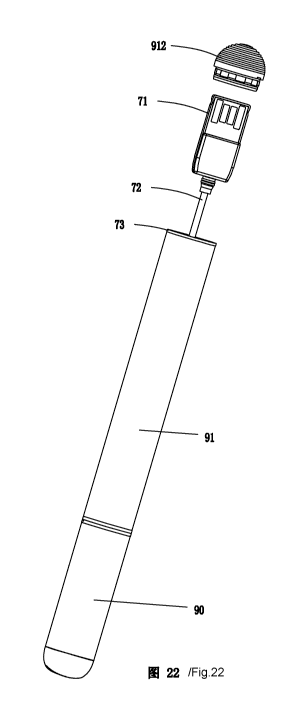
cigarette body for accommodating and positioning the connector, a first
accommodating chamber is defined in the support base for accommodating
the connector and the conductor, the first accommodating chamber having a
wall body defining a cylindrical front portion for allowing the connector
and the conductor to extend out of or retract to the support base, and the
cylindrical front portion corresponds to an inner wall of the cigarette body.
[0007] According to another embodiment of the present invention, the
conductor comprises a movable conductor and a fixing conductor both
2
CA 02878505 2015-01-06
integrally connected with each other over a coupling element disposed in
between the movable conductor and the fixing conductor, the coupling
element is mounted to the support base, one end portion of the movable
conductor is electrically connected to one end portion of the fixing
conductor through the coupling element, the conductor is electrically
connected to the connector through the one end portion of the movable
conductor, and the conductor is electrically connected to a control circuit
unit in the electronic cigarette through another end portion of the fixing
conductor.
[0008] According to another embodiment of the present invention, the
support base is formed with at least one conductor positioning element for
mounting the coupling element, and the coupling element is formed with at
least one mounting hole for being mounted to the at least one conductor
positioning element, the cylindrical front portion of the support base has a
positioning stage radially formed on an outer wall thereof for matching
with the cigarette body, the support base is mounted into the cigarette body,
and the outer wall of the cylindrical front portion is snugly mounted to the
inner wall of the cigarette body and positioned by the positioning stage.
[0009] According to another embodiment of the present invention, the
connector is a universal serial bus (USB) connector, a peg-type or a
pin-type connector, the connector is substantially cylindrical and defined
with the first accommodating chamber and a through hole therein, the outer
wall of the support base is formed with a conductor slit, and the conductor
passes through the through hole from the first accommodating chamber
along the conductor slit to electrically connect the control circuit unit.
3
CA 02878505 2015-01-06
[0010] According to another embodiment of the present invention, the
cigarette body has an inhaling rod and a battery rod, the inhaling rod
comprises an inhaling cylinder, an inhaling nozzle, an atomizer disposed in
the inhaling cylinder, and a cigarette liquid storing cup for storing a
cigarette liquid, the battery rod comprises a barrel, a battery installed in
the
barrel, and a bottom case mounted to a bottom of the barrel, the connecting
device is disposed in the barrel, and the bottom case covers the bottom of
the barrel so as to seal the connecting device in the end of the barrel.
[0011] According to another embodiment of the present invention, the
cigarette liquid storing cup comprises a cup seat and a cup lid both are
spaced apart from each other at a predetermined space and are snugly
mounted onto inner walls of the inhaling cylinder, a guiding tube and a
liquid storing element both are disposed in between the cup seat and the
cup lid, the guiding tube is being internally hollow with two opposite ends
thereof open to outside, and the atomizer is fixedly held by the guiding tube,
a positioning tube is mounted onto outer walls of the guiding tube for
preventing the atomizer from moving in an axial direction of the guiding
tube, the positioning tube and the guiding tube are in interference fit with
each other, and the positioning tube abuts against the atomizer.
[0012] According to another embodiment of the present invention, the
cup seat has a cylindrical cup structure, a positioning pillar formed in the
cup seat for positioning the guiding tube, and a round internal chamber for
receiving the liquid storing element; the cup lid having a substantially
cylindrical lid structure, a circular internal cavity formed in the cup lid
for
receiving the guiding tube, a plurality of air vents formed on a side wall of
the he cup lid, a plurality of ribs formed on an upper wall of the cup lid in
4
CA 02878505 2015-01-06
the circular internal cavity, each of the plurality of ribs having a width
smaller than an inner diameter of the guiding tube, a bottom of the cup lid
extending radially outward to form a flange portion, wherein the flange
portion is serrated and has multiple serrations, the serrations having gaps
formed therebetween for enabling flow of the cigarette liquid to the
cigarette liquid storing cup, two opposite ends of the guiding tube are
respectively positioned by the upper wall of the cup lid and the positioning
pillar of the cup seat, and the flange portion is disposed with respect to the
round internal chamber of the cup seat for positioning two opposite ends of
the liquid storing element.
[0013] According to another embodiment of the present invention, the
inhaling rod and the battery rod are respectively installed with a male
connecting element and a female connector so as to enable the inhaling rod
and the battery rod to be plugged with each other, and the male and female
connecting elements respectively have atomizer electrode elements and
battery electrode elements, whereby the atomizer electrode element and the
battery electrode element are in flexibly contact with each other to realize
electrical connection.
[0014] According to another embodiment of the present invention, the
male connecting element is substantially shaped as a round cover being
internally hollow and has multiple air inlets radially formed at a bottom of
the male connecting element, and a positioning step is formed by extending
outward radially from the bottom of the male connecting element for
abutting against a bottom of the inhaling cylinder, an first accommodating
chamber is formed on the bottom of the male connecting element for being
snugy mounted onto the battery rod, electrode slots are formed on a middle
CA 02878505 2015-01-06
portion of the male connecting element and penetrate the male connecting
element in an axialdirection thereof, and a positioning projection is radially
formed on the bottom of the male connecting element and extends outward
in the axial direction.
[0015] According to another embodiment of the present invention, the
female connecting element is substantially shaped as a round cover and
hasa side wall, an upper wall, an internal chamber defined by te side wall
and the upper wall, a locating step is formed on the side wall adjacent to the
upper wall and extends outward radially from the female connecting elemnt
for fitting to the battery rod, an inserting peg is disposed on the upper wall
and extends outward in an axial direction of the female connecting element
for being inserted into the first accommodating chamber of the male
connecting element, the upper wall is concavel formed with a plurality of
positioning grooves for positioning the positioning projectionof the male
connecting element, threading holes are formed in and penetrate the female
connecting eleent in the axial direction, two electrode slits extend in the
axial direction for positioning the battery electrode elements, and two
internal channels for the insertion of the atomizer electrode elements with
which the battery electrode elements re in flexible contact in the internal
channels.
[0016] According to another embodiment of the present invention, the
atomizer comprises at least one heating element, the atomizer electrode
elements includes an atomizer first electrode element and an atomizer
second electrode element respectively electrically connect with positive and
negative electrodes of the at least one heating element, the battery electrode
elements includes a battery first electrode element and a battery second
6
CA 02878505 2015-01-06
electrode element respectively electrically connect with positive and
negative electrodes of the battery, and the atomizer first and second
electrode elements and the battery first and second electrode elements are
all made of flexible metal conductive sheets.
[0017] According to another embodiment of the present invention, the
atomizer first electrode element is a metal conductive sheet being flexibly
deformable and is formed with a soldering plate of a soldering hole at one
end thereof, a flexible contact plate being flexibly deformable and formed
at another end of the atomizer first electrode element, and an engaging plate
being flexibly deformable and formed at a middle of the atomizer first
electrode element for engaging with the male connecting element; and the
atomizer second electrode element has a structure same as that of the
atomizer first electrode element.
[0018] According to another embodiment of the present invention, the
battery first electrode element is a metal conductive sheet being flexibly
deformable and is formed with a soldering plate of a soldering hole at one
end thereof, a flexible contact plate being flexibly deformable and formed
at another end of the battery fist electrode element, and an engaging plate
being flexibly deformable and formed at a middle of the battery fist
electrode element for engaging with the female connecting element; and the
battery second electrode element has a structure same as that of the battery
first electrode element.
[0019] According to another embodiment of the present invention, the
atomizer first and second electrode elements and the battery first and
second electrode elements each is formed with a soldering plate having a
7
CA 02878505 2015-01-06
soldering hole at one end thereof, a flexible contact plate being flexibly
deformable and formed at another end thereof, and an engaging plate being
flexibly deformable and formed at a middle for engaging with
corresponding male or female connecting element, the atomizer first and
second electrode elements respectively electrically connect the negative
electrodes of the at least one heating element through the soldering plates
and soldering holes, the battery first and second electrode elements
respectively electrically connect the positive and negative electrodes of the
battery through the soldering plates and soldering holes, and the atomizer
first and second electrode elements are in flexible contact with the battery
first and second electrode elements through the flexible contact plates
thereof to realize electrical connection.
[0020] Accordingly, the present invention has the advantages as follows:
first, because the USB connector and the conductor are disposed in the
electronic cigarette, the electronic cigarette is convenient to use and is
aesthetic.
[0021] Secondly, the support base defines a first accommodating
chamber formed therein for accommodating the USB connector and a
conductor accommodating chamber for accommodating the conductor,
whereby the USB connector and the conductor are freely to move therein.
[0022] Thirdly, the inhaling rod and the battery rod are pluggable to each
other which enables a convenient and quick assembly or disassembly.
[0023] Fourthly, the positive and negative electrodes of the atomizer
electrically connect the positive and negative electrodes of the battery in a
manner that the atomizer first and second electrode elements are in flexibly
8
CA 02878505 2015-01-06
contact with the battery first and second electrode elements, whereby the
technical craft is being simplified, assembly is easy to be done, and
electrical connection is reliable.
[0024] Fifthly,
structure of the cup lid of the cigarette liquid storing cup is
configured to efficiently discharge smoke and to enable a quickly flow of a
cigarette liquid to the cigarette liquid storing cup.
[0025] Finally, a positioning tube is mounted onto outer walls of the
guiding tube so as to further position and hold the atomizer in the guiding
tube
[0026] Detailed description of the present invention is given below in
conjunction with appendix drawings.
BRIEF DESCRIPTION OF THE DRAWINGS
[0027] FIG. 1 is a front elevational view of an electronic cigarette of the
present invention;
[0028] FIG 2 is a cross-sectional view taken along line A-A in FIG. 1;
[0029] FIG. 3 is an enlarged view of a M portion indicated in FIG. 2;
[0030] FIG. 4 is an exploded view of an inhaling rod of the electronic
cigarette of the present invention;
[0031] FIG. 5 is an exploded view of a battery rod of the electronic
cigarette of the present invention;
[0032] FIG 6 is a first perspective view of a cup lid of a cigarette liquid
9
CA 02878505 2015-01-06
storing cup of the inhaling rod of the present invention;
[0033] FIG 7 is a second perspective view of the cup lid of the cigarette
liquid storing cup of the inhaling rod of the present invention;
[0034] FIG 8 is a cross-sectional view of a cup seat of the cigarette liquid
storing cup of the inhaling rod of the present invention;
[0035] FIG 9 is a perspective view of a male connecting element of the
inhaling rod of the present invention;
[0036] FIG 10 is a cross-sectional view of the male connecting element
of the inhaling rod of the present invention;
[0037] FIG 11 is a perspective view of a female connecting element of
the inhaling rod of the present invention;
[0038] FIG 12 is a cross-sectional view of the female connecting element
of the inhaling rod of the present invention;
[0039] FIG. 13 is
a perspective view of an atomizer first electrode
element of the inhaling rod of the present invention;
[0040] FIG 14 is a perspective view of a battery first electrode element of
the battery rod of the present invention;
[0041] FIG 15 is a first perspective view of a support base of the battery
rod of the present invention;
[0042] FIG. 16 is a second perspective view of the support base of the
battery rod of the present invention;
CA 02878505 2015-01-06
[0043] FIG 17 is a schematic view showing a state that a Connecting
device is mounted in the support base according to the present invention;
[0044] FIG. 18 is a cross-sectional view of FIG 17;
[0045] FIG. 19 is a schematic view showing a state that the connecting
device is pulled out of the support base according to the present invention;
[0046] FIG. 20 is a cross-sectional view of FIG 19;
[0047] FIG. 21 is a schematic view showing a state that a bottom case is
pulled out of the battery rod according to the present invention;
[0048] FIG 22 is a schematic view showing a state that the connecting
device is pulled out of the battery rod according to the present invention;
and
[0049] FIG 23 is a schematic view showing a state that the inhaling rod is
pulled out of the battery rod.
DESCRIPTION OF THE PREFERRED EMBODIMENTS
[0050] As shown in FIGS. 1 to 23, a first embodiment of the present
invention is to provide an electronic cigarette, comprising a cigarette body
having a inhaling rod 90 and a battery rod 91. The cigarette body is installed
with a retractable connecting device 7. The connecting device 7 is
retractably disposed in the cigarette body so as to be hidden therein. When
not in use, the connecting device 7 is foldably retracted to be completely
hidden within the cigarette body together. When in use, the connecting
device 7 is being pulled away to extend to a predetermined length, whereby
11
CA 02878505 2015-01-06
electrically connecting the electronic cigarette to an external electronic
device or power. The connecting device 7 is intended to charge the
electronic cigarette and to transmit data as well, such as multimedia data, so
as to satisfy requirements of multi functions of the electronic cigarette. The
connecting device 7 at least comprises a connector 71 and a conductor 72 of
which a length is extendable. The connector 71 is one of a universal serial
bus (USB) connector, a peg-type, a pin-type or other appropriate connector.
A preferable embodiment described below is exemplified by the USB
connector 71 in order to achieve the object of charging the electronic
cigarette.
[0051] As shown in FIGS. 2 to 4, the inhaling rod 90 comprises an
inhaling cylinder 1, an atomizing device 2 for atomizing a cigarette liquid, a
cigarette liquid storing cup 3 for storing the cigarette liquid, an inhaling
nozzle 4, and a male connecting element 5 for connecting the battery rod 91.
In this embodiment, the inhaling cylinder 1 is a hollow elongated tube
structure, and the inhaling nozzle 4 and the male connecting element 5 are
mounted to opposite end portions of the inhaling cylinder 1.
[0052] As shown in FIG. 3, the inhaling nozzle 4 has a substantially
cylindrical body 41, which is internally hollow and has an inhaling hole 42
penetrating the cylindrical body 41 in an axial direction thereof. The
inhaling nozzle 4 is made of a resilient material, and is detachably plugged
into a top end of the inhaling cylinder 1.
[0053] As shown in FIGS. 3, 4, 9 and 10, the male connecting element 5,
made of a flexible material, is disposed at a bottom of the inhaling cylinder
1 and has a shape fitted to the inhaling cylinder 1. cThe male connecting
12
CA 02878505 2015-01-06
element 5 is substantially shaped as a round cover being internally hollow,
and has multiple air inlets 51 formed at a bottom thereof along peripheral
rims of the male connecting element 5 for allowing the outside air to flow in
the inhaling cylinder 1. A positioning step 52 is formed by extending
outward radially from the bottom of the male connecting element 5 for
abutting against the bottom of the inhaling cylinder 1. A first
accommodating chamber 53 is formed on the bottom of the male connecting
element 5 for being snugly mounted onto the battery rod 91. Electrode slots
54 and air vents 55 are respectively formed on a middle portion of the male
connecting element 5 and penetrate the male connecting element 5 in an
axial direction thereof. A positioning projection 56 is formed on the bottom
of the male connecting element 5 and extends outward in the axial direction
for being inserted into the battery rod 91.
[0054] As shown in FIGS. 3, 4 and 13, the inhaling cylinder 1 further
comprises an atomizer first electrode element 17 and an atomizer second
electrode element 19 for electrically connecting electrodes of the battery rod
91. Both of the atomizer first and second electrode elements 17 and 19 are
disposed in the male connecting element 5. The atomizer first electrode
element 17 is a flexibly deformable metal sheet and has a soldering plate
171 at one end thereof, the soldering plate 171 defining a soldering hole, a
flexible contact plate 172 being flexibly deformable and formed at another
end thereof, and an engaging plate 173 being flexibly deformable and
formed at a middle of the atomizer first electrode element 17 for engaging
with the male connecting element 5. The atomizer second electrode element
19 has a structure same as that of the atomizer first electrode element 17.
13
CA 02878505 2015-01-06
[0055] As shown in FIGS. 3 to 5, the atomizing device 2 comprises an
atomizer 21 installed in the inhaling rod 90, an atomizer switch27, a switch
base 28, and a control circuit unit for controlling the atomizer 21.
[0056] The atomizer 21 is intended to atomize the cigarette liquid to be
smoke, and comprises a heating element 211 and fiber elements 212. The
heating element 211 is wound around the fiber elements 212 and held in a
cigarette liquid storing cup 3. The fiber elements 212 are intended to absorb
the cigarette liquid for the heating element 211 to heat and atomize. The
fiber elements 212 function as a sponge that is capable of absorbing and
preserving water, and are made of glass fiber or a material having characters
of absorbing and isolating liquid, such as cotton, and have a tubular shape.
In this embodiment, the number of the fiber elements 212 is three (not
limited thereby). The three fiber elements 212 as a whole are disposed in the
cigarette liquid storing cup 3. The heating element 211 is wound around
outer surfaces of the whole three fiber element 212, wherein two opposite
ends of the heating element 211 respectively extend out of the cigarette
liquid storing cup 3 for electrically connecting with the atomizer first
electrode element 17 and the atomizer second electrode element 19 of the
male connecting element 5.
[0057] As shown in FIGS. 3 and 4, the cigarette liquid storing cup 3
comprises a cup seat 31, a cup lid 33, a guiding tube 35, a liquid storing
element 37, and a positioning tube 39. The cup seat 31 and cup lid 33 both
are spaced apart from each other at a predetermined space and are in snug-fit
engagement with inner walls of the inhaling cylinder 1. The guiding tube 35
is mounted between the cup seat 31 and the cup lid 33. The liquid storing
14
CA 02878505 2015-01-06
element 37 is disposed outside the guiding tube 35 between the cup seat 31
and the cup lid 33. The positioning tube 39 is intended to position the
atomizer 21.
[0058] In this embodiment, the cup seat 31 (referring to FIGS. 3, 4 and 8)
has a cylindrical cup structure, a round side wall 318, a round cup bottom
319, a positioning pillar 311 extends in an axial direction of cup seat 31
from a middle of the cup bottom 319, wherein the round side wall 318 and
the positioning pillar 311 cooperatively define a round internal chamber 317.
An air channel 312 is formed in the positioning pillar 311 and penetrates the
positioning pillar 311 and the bottom cup 319 in its axial direction. A
plurality of threading channels 313 are formed on and penetrate the cup
bottom 319 for the heating element 211 to pass through. An outer surface of
the side wall 318 is formed with a jam-fit ring 314. The cup seat 31 is
snugly fitted to an inner wall of the inhaling cylinder 1 with the side wall
318 and the jam-fit ring 314.
[0059] The cup lid
33 (referring to FIGS. 3, 4, 6 and 7) is made of silica
gel, and has a shape and size corresponding to the inner wall of the inhaling
cylinder 1. In this embodiment, the cup lid 33 is a hollow cylindrical lid
structure, and has a side wall 338 and an upper wall 339 both cooperatively
define a circular internal cavity 337 having an inner diameter greater than an
outer diameter of the guiding tube 35 in order for flow of smoke. A plurality
of air vents 336 are formed on a side wall of the cup lid 33 and communicate
with the circular internal cavity 337. A plurality of ribs 335 are formed on
the upper wall 339 and located in the circular internal cavity 337. In this
embodiment, there are three ribs 335 radially disposed on a middle portion
CA 02878505 2015-01-06
of the upper wall 339, whereby when the guiding tube 35 is engaged with
the ribs 224, a top end of the guiding tube 35 and the upper wall 339 jointly
form a gap as a venting path 334 communicating with the circular internal
cavity 337. A bottom of the side wall 338 extends radially outward to form a
flange portion 333 which has multiple arc cutouts 332 and thus render the
flange portion 333 serrated. An outer diameter of the flange portion 333 is
slightly greater than an inner diameter of the inhaling cylinder 1. The cup
lid
33 is snugly fitted with the inner wall of the inhaling cylinder 1 through the
flange portion 333. The circular internal cavity 337 of the cup lid 33
corresponds to the positioning pillar 311 of the cup seat 31 and both
respectively position the opposite ends of the guiding tube 35. The flange
portion 333 of the cup lid 33 and the round internal chamber 317 of the cup
seat 31 respectively fix two opposite ends of the liquid storing element 37.
When the cigarette liquid is running out, pull out the inhaling nozzle 4 and
remain the cup lid 33, and the cigarette liquid can be refilled in the
cigarette
liquid storing cup 3 from the arc cutouts 332 of the cup lid 33. The cigarette
liquid is absorbed by the liquid storing element 37 and is capable of being
repeatedly refilled in a convenient way.
[0060] The guiding tube 35 (referring to FIGS. 3 and 4) is intended to
support the liquid storing element 37 and the fiber elements 212 and limit
the height of the cigarette liquid storing cup 3, and further functions as a
path to outside of the inhaling cylinder 1 for the flow of smoke produced by
the atomizer 21 atomizing the cigarette liquid. In this embodiment, the
guiding tube 35 is an insulating hollow cylinder, made of a plastic or fiber
material, such as a fiberglass sleeve. The guiding tube 35 has top and bottom
ends, wherein the top end is mounted in the circular internal cavity 337 of
16
CA 02878505 2015-01-06
the cup lid 33, and the bottom end is snugly mounted to the positioning
pillar 311 of the cup seat 31. The guiding tube 35 is formed with a retaining
slot 351 penetrating side walls of the guiding tube 35 in a radial direction
for
retaining the fiber elements 212. The fiber elements 212 are fixed in the
retaining slot 351 with two ends of the fiber elements 212 abutting against
the liquid storing element 37 so as to absorb the cigarette liquid for the
heating element 211 to atomize.
[0061] The liquid storing element 37 (referring to FIGS. 3 and 4) is
intended to absorb and store the cigarette liquid in the cigarette liquid
storing cup 3 so as to allow the atomizer 2 to atomize the cigarette liquid.
The liquid storing element 37 functions as a sponge that is capable of
absorbing and preserving water, and is made of glass fiber or a material
having characters of absorbing and isolating liquid, such as cotton. The
liquid storing element 37 is a hollow cylindrical structure and is disposed
outside the guiding tube 35. One end of the liquid storing element 37 is
inserted in the round internal chamber 317 of the cup seat 31 and the other
end abuts against the bottom of the cup lid 33 such as the liquid storing
element 37 is disposed between the cup seat 31 and the cup lid 33. Two ends
of the fiber elements 212 abut against inner walls of the liquid storing
element 37 to absorb the cigarette liquid for the heating element 211 to
atomize.
[0062] The positioning tube 39 (referring to FIGS. 3 and 4) is intended to
locate a position of the atomizer 21 with respect to the guiding tube 354.
The positioning tube 39 is an insulating hollow cylinder being mountable
onto outer walls of the guiding tube 35, and is made of a plastic or fiber
17
CA 02878505 2015-01-06
material, such as a fiberglass sleeve. The positioning tube 39 and the guiding
tube 35 are in interference fit with each other. A bottom of the positioning
tube 39 abuts against the atomizer 21 to prevent the atomizer 21 from
moving in an axial direction of the guiding tube 35.
[0063] In this embodiment, the cigarette liquid storing cup 3 defines a
smoke path therein that is formed by the air channel 312 of the cup seat 31,
a hollow passageway of the guiding tube 35, the venting path 334 of the cup
lid 33, the circular internal cavity 337 and air vents 336 all together.
[0064] As shown in FIGS. 2, 3 and 5, the battery rod 91 comprises a
barrel 910, a female connecting element 911 and a bottom case 912
respectively mounted to opposite ends of the barrel 910, a battery 913
installed in the barrel 910, and a battery first electrode element 914 and a
battery second electrode 915 electrically connected to two electrodes of the
battery 913.
[0065] As shown in FIGS. 3, 11 and 12, the female connecting element
911 is configured to mate with the male connecting element 5, and is made
of a flexible plastic material. The female connecting element 911 is mounted
to one end of the male connecting element 5 so as to connect the inhaling
rod 90 and the battery rod 91. The female connecting element 911 is
substantially shaped as a round cover, and comprises a side wall 9111, an
upper wall 9112, an internal chamber 9119 is defined by the side wall 9111
and the upper wall 9112, a locating step 9113 is formed on the side wall
9111 adjacent to the upper wall 9112 and extends outward radially from the
female connecting element 911 for fitting to the barrel 910, and an inserting
peg 9114 is disposed on the upper wall 9112 and extends outward in an axial
18
CA 02878505 2015-01-06
direction of the female connecting element 911 for being inserted into the
first accommodating chamber 53 of the male connecting element 5. The
upper wall 9112 is concavely formed with a plurality of positioning grooves
9115 for receiving the positioning projection 56 of the male connecting
element 5. Threading holes 9116 are formed in and penetrate the female
connecting element 911 in the axial direction, and two electrode slits 9117
and internal channels 9118 extend in the axial direction for positioning the
battery first electrode element 914 and the battery second electrode element
915. The two internal channels 9118 for the insertion of the atomizer first
and second electrode elements 17 and 19 with which the battery first and
second electrode elements 914 and 915 are in flexible contact in the internal
channels 9118.
[0066] As shown in FIGS. 2 and 5, the bottom case 912 is mounted to the
bottom end of the barrel 910 for sealing the USB connector 71. The bottom
case 912 is further equipped with a sealing ring 916. It is understandable
that
to prevent the bottom case 912 from coming off the barrel 910 or lost after
being pulled away, the bottom case 912 is further coupled with a coupling
strap to connect the barrel 910. The coupling strap is capable of being
disposed in the barrel 910 or integrally formed with a connecting portion or
other connecting structure in order to mount the bottom case 912 onto the
barrel.
[0067] As shown in FIGS. 3, 4 and 14, the battery first and second
electrode elements 914 and 915 are respectively positioned in the electrode
slits 9117. The battery first electrode element 914 is a flexibly deformable
metal sheet, and has a soldering plate 9141 of a soldering hole at one end of
19
CA 02878505 2015-01-06
the battery first electrode element 914, a flexible contact plate 9142 being
flexibly deformable and formed at another end thereof, and an engaging
plate 9143 being flexibly deformable and formed at a middle thereof for
engaging with the female connecting element 911. The battery second
electrode element 915 has a structure same as that of the battery first
electrode element 914. When the inhaling rod 90 and the battery rod 91 are
being plugged together, the battery first and second electrode elements 914
and 915 of the female connecting element 911 are in flexibly contact with
the atomizer first and second electrode elements 17 and 19 whereby
realizing electrical connection. The battery first and second electrode
elements 914 and 915 respectively electrically connect the positive and
negative electrodes of the battery 913 through the soldering plates 9141 and
soldering holes. The atomizer first and second electrode elements 17 and 19
are in flexible contact with the battery first and second electrode elements
914 and 915 through the flexible contact plates thereof to realize electrical
connection. Accordingly, the electronic cigarette is capable of being
assembled conveniently with a simplified craft and providing a reliable
electrical connection.
[0068] As shown in FIGS. 3 and 5, in this embodiment, the atomizer
switch 27 and the switch base 28 are disposed in the battery rod 91.
Specifically, the atomizer switch 27 is disposed in the switch base 28, while
the switch base 28 is disposed in the internal chamber 9119 of the female
connecting element 911. Two electrodes of the atomizer switch 27 are
electrically connected to the battery first and second electrode elements 914
and 915 through two wires (not shown). The atomizer switch 27 is a
pneumatic type switch that is switchable according to pneumatic vibration
CA 02878505 2015-01-06
for power on or off. The atomizer switch 27 and the battery 913 are
electrically connected to the control circuit unit.
[0069] As shown in FIGS. 2, 5, 15 to 22, the connecting device 7 has the
connecting device 71, a conductor 72, and a support base 73. In this
embodiment, the connecting device 7 is disposed in the battery rod 91.
[0070] The connecting device 71 is intended to connect an external power
in order to charge the battery 911. The USB connector 71 is also capable of
transmitting, downloading, or storing multimedia data when the electronic
cigarette is equipped with portable storage devices, MP3, MP4 or other
multimedia functions. The connecting device 71 is mounted in the battery
rod 91 through the support base 73.
[0071] As shown in FIGS. 15 to 22, the support base 73 is being
substantially cylindrical, and defines an accommodating chamber 731
therein configured to receive the connecting device 71 and the conductor 72.
The support base 73 is further formed with two conductor positioning
elements 735 for positioning the conductor 72. The two conductor
positioning elements 735 are disposed on a side wall of the support base 73
and each is exemplified by a screw post having internal screw threads. A
positioning stage 736 is radially formed on an outer wall of a front portion
of the support base 73 for matching with a bottom of the barrel 910. A
bottom board 737 is formed at a bottom of the support base 73, and defines a
through hole 738 and an opening 739 therein . Furthermore, the outer wall
of the support base 73 is formed with a conductor slit (not labeled).
[0072] In this embodiment, the first accommodating chamber 731
comprises a front portion 7311, a middle portion 7312, and a rear portion
21
CA 02878505 2015-01-06
7313 all connected with each other in sequence. The front portion 7311 is
cylindrical for allowing the USB connector 71 and the conductor 72 to
extend out of or retract to the support base 73. The middle portion 7312 is
being substantially cylindrical or other shapes and extends outwards from a
bottom surface of the front portion 7311 in an axial direction of the support
base 73. The USB connector 71 is wedged into the middle portion 7312. The
rear portion 7313 is intended to accommodate the conductor 72 when the
conductor 72 is being retracted. The rear portion 7313 is formed by the
bottom board 318 and two parallel clamping boards (not shown) extending
in the axial direction. The rear portion 7313 is hollow cylindrical or has
other shapes for the purpose of accommodating the conductor 72 and
allowing the conductor 72 to freely move therein. A penetrating hole is
formed between the middle portion 7312 and the rear portion 7313. An outer
wall of the front portion 7311 is fitted with the inner wall of the barrel
910.
The support base 73 is mounted in the barrel 910 through a snug-fit of the
outer wall of the front portion 7311 and the barrel 910, and is positioned by
the positioning stage 736 (referring to FIGS. 2, 21, and 22). In this
embodiment, the conductor positioning elements 735 are disposed on an
outer side of the middle portion 7312 of the first accommodating chamber
731 and integrated with the support base 73.
[0073] One end of the conductor 72 is connected to the USB connector
71 so as to extend an applicable distance of the USB connector 71. Another
end of the conductor 72 is connected to the control circuit unit in order for
charging or other functions. The conductor 72 comprises a movable
conductor 721, a fixing conductor 722, and a coupling element 723 for
coupling the movable conductor 721 and the fixing conductor 722. The
22
CA 02878505 2015-01-06
coupling element 723 is positioned by an inner wall or outer wall of the first
accommodating chamber 731 so as to retain the fixing conductor 722. One
end of the movable conductor 721 is electrically connected to the fixing
conductor 722 through the coupling element 723. The other end of the
movable conductor 721 is electrically connected to the USB connector 71.
One end of the fixing conductor 722 is electrically connected to the movable
conductor 721 through the coupling element 723. Another end of the fixing
conductor 722 is attached on the outer wall of the support base 73 along the
conductor slit to pass through the opening 739 and then electrically connect
the control circuit unit. The fixing conductor 722 is fixed in the battery rod
91 without being retracted or extended. The coupling element 723 is
substantially U-shaped and forms two mounting holes at opposite sides
thereof for mounting the conductor positioning elements 735. The coupling
element 723 is fixedly mounted onto the conductor positioning elements 735,
with screws screwed in the conductor positioning elements 735.
Alternatively, the coupling element 735 is capable of having other shapes
and being mounted in other ways. Therefore, the fixing conductor 722 of the
conductor 72 is being positioned and retained in place so as to prevent the
electrical connection of the conductor 72 and the control circuit unit from
being affected by the movable conductor when the moveable conductor 721
is being drawn.
[0074] When the connecting device 7 is not in use, the USB connector 71
is manually depressed into the support base 73, and the bottom case 912 is
being mounted, and thus the moveable conductor 721 is disposed in a
conductor receiving slot 732 formed in the support base 73 (referring to FIG
18). When the connecting device 7 is in use, first remove the bottom case
23
CA 02878505 2015-01-06
912, and then pull the USB connector 71 away of the support base 73 to
come out of the barrel 910, whereby one end of the moveable conductor 721
reaches out of the barrel 910 from the first accommodating chamber 731 in
conjunction with the USB connector 71 (referring to FIG 20), and the
movable conductor 721 brings the USB conductor 71 to connect with the
external electronic device or power within a predetermined distance. In this
embodiment, the number of the fixing conductor 722 is three, the three
fixing conductors 722 respectively standing for a positive wire, a negative
wire, and a signal wire for respectively connecting with respective
electrodes of the control circuit unit. The connecting device 71 and the
conductor 72 are disposed in the battery rod 91, and therefore enables a
convenient usage and beautifies the electronic cigarette. The support base 73
defines the first accommodating chamber 731 for accommodating the USB
connector 71 and the conductor 72 in a manner that the USB connector 71
and the conductor 72 are capable of freely moving therein.
[0075] The inhaling rod 90 and the battery rod 91 are capable of being
engaged or plugged together. As an embodiment shown in FIG 23, the
inhaling rod 90 and the battery rod 91 are detachably connected with each
other through the male connecting element 5 snugly plugged with the female
connecting element 911 in a convenient way. Alternatively, the electronic
cigarette of the present invention is an one-piece element such that the
inhaling cylinder 1 of the inhaling rod 90 and the barrel 910 of the battery
rod 91 are integrally formed as an one-piece case body. Also, the inhaling
cylinder 1, the barrel 910, and the inhaling nozzle 4 are all integrally
formed.
24
CA 02878505 2015-01-06
[0076] It is understood that the invention may be embodied in other
forms within the scope of the claims. Thus the present examples and
embodiments are to be considered in all respects as illustrative, and not
restrictive, of the invention defined by the claims.