Note: Descriptions are shown in the official language in which they were submitted.
TITLE
POWER LINE MAINTENANCE MONITORING
[001] Intentionally left blank.
COPYRIGHTS
[002] All rights, including copyrights, in the material included herein
are vested in and the property of the Applicants. The Applicants retain and
reserve all rights in the material included herein, and grant permission to
reproduce the material only in connection with reproduction of the granted
patent and for no other purpose.
BACKGROUND
[003] A power line is a system of many components. These
components include conductors, splices, dead-ends, insulators, and
structures. Power line monitoring and inspection has conventionally been
done manually on a scheduled basis. This requires a utility company crew
with equipment to visit each structure on the power line to visually inspect
the components. Additionally, some utility companies use a helicopter to
"fly" the power line and perform a visual and thermal inspection. Generally a
utility company will determine an inspection schedule, attempting to balance
cost of the inspection verses cost of repairing the failure and service
interruption. With conventional power line monitoring and inspection,
however, potential component failure points may go undetected, especially if
the inspections occur when the power line is lightly loaded. Accordingly,
conventional power line monitoring and inspection is time consuming,
- 1 -
CA 2878674 2019-10-01
. .
expensive, prone to inaccuracy, and components can fail between extended
inspection cycles.
SUMMARY
[004] This Summary is provided to introduce a selection of concepts
5 in a simplified form that are further described below in the Detailed
Description. This Summary is not intended to identify key features or
essential features of the claimed subject matter. Nor is this Summary
intended to be used to limit the claimed subject matter's scope.
[005] According to a general aspect, there is provided a method of
10 providing monitoring. The method comprises receiving a distance between
a
first sag transceiver and a second sag transceiver comprising a first
distance; receiving a distance between the first sag transceiver and a third
sag transceiver comprising a second distance; receiving a distance between
the second sag transceiver and the third sag transceiver comprising a third
15 distance; calculating a current location of a point on a span of
conductor
based upon the first distance, the second distance, and the third distance;
and calculating a sag of the span of conductor based upon the calculated
current location of the point on the span of conductor and a previous location
of the point on the span of conductor.
20 [005a] According to another general aspect, there is provided a
method of providing monitoring, the method comprising: receiving a first
distance between a first sag transceiver and a second sag transceiver
comprising a first distance, wherein receiving the first distance between the
first sag transceiver and the second sag transceiver comprises; receiving a
- 2 -
CA 2878674 2019-10-01
. .
time stamped signal at the second transceiver from the first transceiver, the
time stamped signal comprising a time stamp indicating a time when the time
stamped signal left the first transceiver, determining a time of receipt of
the
time stamped signal at the second transceiver, and determining the first
5 distance based on the time stamp on the received time stamped signal and
the time of receipt of the time stamped signal; receiving a second distance
between the first sag transceiver and a third sag transceiver; receiving a
third distance between the second sag transceiver and the third sag
transceiver; calculating a current location of a point on a span of conductor
10 based upon the first distance, the second distance, and the third
distance,
wherein the first sag transceiver, the second sag transceiver, and the third
sag transceiver are located on the span; calculating a sag of the span of
conductor based upon the calculated current location of the point on the
span of conductor and a previous location of the point on the span of
15 conductor, wherein calculating the sag comprises calculating a real-time
sag;
determining a clearance between the span of conductor based on the
calculated sag and a baseline data; and providing an alert when the
clearance is less than a predetermined value, wherein the predetermined
value is based on one or more safety codes.
20 [005b] Other possible aspect(s), object(s), embodiment(s), variant(s)
and/or advantage(s) of the present invention, all being preferred and/or
optional, are briefly summarized hereinbelow.
[005c] Monitoring may be provided. First, data may be received
comprising a current location of a point on a span of conductor or a current
- 2a -
CA 2878674 2019-10-01
angle of a section of the span of conductor. Next, a sag may be calculated
of the span of conductor based upon the current location of the point on the
span of conductor and the current angle of the section of the span of
conductor. An alert may then be provided when the calculated sag is
outside of a predetermined range for the span.
[006] Both the foregoing general description and the following
detailed description provide examples and are explanatory only.
Accordingly, the foregoing general description and the following detailed
description should not be considered to be restrictive. Further, features or
variations may be provided in addition to those set forth herein. For
- 2b -
CA 2878674 2019-10-01
CA 02878674 2015-01-06
WO 2014/011760
PCT/1JS2013/049908
example, embodiments may be directed to various feature combinations and
sub-combinations described in the detailed description.
BRIEF DESCRIPTION OF THE DRAWINGS
[007] The accompanying drawings, which are incorporated in and
constitute a part of this disclosure, illustrate various embodiments of the
present invention. In the drawings:
[008] FIG. 1 shows an operating environment;
[009] FIG. 2 shows a power line monitor;
[010] FIG. 3 shows an operating environment for the power line
monitor;
[011] FIG. 4 shows a SCADA system;
[012] FIG. 5 is a flow chart of a method for providing maintenance
monitoring;
[013] FIG. 6 shows an operating environment; and
[014] FIG. 7 shows an operating environment.
DETAILED DESCRIPTION
[015] The following detailed description refers to the accompanying
drawings. Wherever possible, the same reference numbers are used in the
drawings and the following description to refer to the same or similar
elements. While embodiments of the invention may be described,
modifications, adaptations, and other implementations are possible. For
example, substitutions, additions, or modifications may be made to the
elements illustrated in the drawings, and the methods described herein may
be modified by substituting, reordering, or adding stages to the disclosed
3
CA 02878674 2015-01-06
WO 2014/011760
PCT/1JS2013/049908
methods. Accordingly, the following detailed description does not limit the
invention.
[016] Electric power lines are systems of many components. These
components comprise, but are not limited to, conductors, conductor splices,
conductor dead-ends, insulators, strings of insulators (i.e., insulator
strings,)
insulator string supports, structures, and structure grounds. Utility
companies may manually inspect these components on a scheduled basis.
These manual inspections are time consuming, expensive, prone to
inaccuracy, and components may fail between extended manual inspection
cycles.
[017] Consistent with embodiments of the invention, a real-time
power line maintenance monitoring system may provide a utility company
with information on the status of a power line, the interpretation of this
information, and display of this information in a manner that may allow the
utility company to optimize the operation and maintenance of the power line.
This may allow for increased power line reliability as the utility company
may be able to determine if the power line is approaching its clearance limit
or if a monitored component is failing. Embodiments of the invention may
allow "continuous" monitoring of power line components. This continuous
monitoring may reduce inspection expenses over conventional manual
processes and provide earlier indication of potential component failure.
[018] .FIG. 1 shows an operating environment 100 used to transmit
or deliver electrical power. As shown in FIG. 1, operating environment 100
may include a structure 102, a power line monitor 105, a conductor 110, an
insulator string 115, an insulator string support 120, a conductor splice 125,
4
CA 02878674 2015-01-06
WO 2014/011760
PCT/1JS2013/049908
and a structure ground 130. Structure 102 may support conductor 110.
While structure 102 is shown in FIG. 1 as a galvanized steel lattice tower,
structure 102 may comprise any structure configured to support conductor
110 such as a steel pole structure, a wooden pole structure, or a structure
made of any material configured in any way.
[019] Conductor 110 may comprise any type conductor used to
transmit electric power such as, but not limited to, Aluminum Conductor
Steel Reinforced (ACSR). Conductor splice 125 may comprise any
component configured to splice conductor 110. Insulator string 115 may
comprise any component configured to insulate conductor 110 from
structure 102. Insulator string support 120 many comprise any component
configured to attach insulator string 115 to structure 102. Structure ground
130 may comprise any component that grounds structure 102 to the Earth,
for example, a grounding rod(s) and a connector.
[020] FIG. 2 shows power line monitor 105 in more detail. As shown
in FIG. 2, power line monitor 105 may include a processing unit 210 and a
memory 215. Memory 215 may include a monitoring software module 220
and a database 225. While executing on processing unit 210, monitoring
software module 220 may perform processes for providing maintenance
monitoring including, but not limited to, one or more of the stages of a
method 500 as described below in greater detail with respect to FIG. 5.
[021] Power line monitor 105 may also include a communications
package 230 that may include and antenna 235 and may be connected to
processing unit 210. Communications package 230 may transmit status
data collected from power line monitor 105 and may receive other data
5
CA 02878674 2015-01-06
WO 2014/011760
PCT/US2013/049908
including control data. Communications package 230 may communicate
over a network (not shown). The network may comprise, for example, a
local area network (LAN) or a wide area network (WAN). When a LAN is
used as the network, a network interface located at power line monitor 105
may be used to interconnect any other processor on the network. When the
network is implemented in a WAN networking environment, such as the
Internet, power line monitor 105 may include an internal or external modem
(not shown) or other means for establishing communications over the WAN.
Further, in utilizing the network, data sent over the network may be
encrypted to insure data security by using encryption/decryption techniques.
[022] In addition to utilizing a wire line communications system, a
wireless communications system, or a combination of wire line and wireless
may be utilized as the network. Wireless may be defined as radio
transmission via the airwaves. However, it may be appreciated that various
other communication techniques can be used to provide wireless
transmission, including infrared line of sight, cellular, microwave,
satellite,
packet radio, and spread spectrum radio. For example, power line monitor
105 may communicate across a wireless interface such as, for example, a
cellular interface (e.g., general packet radio system (GPRS), enhanced data
rates for global evolution (EDGE), global system for mobile communications
(GSM)), a wireless local area network interface (e.g., WLAN, IEEE 802), a
bluetooth interface, WiFi, WiMax, another RF communication interface,
and/or an optical interface. Furthermore, power line monitor 105 may
communicate over a power line carrier system.
6
CA 02878674 2015-01-06
WO 2014/011760
PCT/1JS2013/049908
[023] Power line monitor 105 may communicate with a plurality of
status transducers. The status transducers may include, but are not limited
to, a splice temperature transducer 230, a conductor temperature transducer
235, a dead-end temperature transducer 240, a conductor motion
transducer 245, a conductor vibration transducer 250, a support vibration
transducer 255, a structure vibration transducer 260, a structure ground
transducer 265, and an insulator breakdown transducer 270, an ambient air
temperature transducer (not shown), all of which may collect and
communicate status data to processing unit 210. The status transducers
may communicate with processing unit 210 in any way. For example, the
status transducers may communicate with processing unit 210 either over a
wire or wirelessly, directly or through the network, for example.
Furthermore, the status transducers and power line monitor 105 may be
read wirelessly by a fixed wing aircraft or helicopter.
[024] The plurality of status transducers may be programmed with
limits such that they can make a determination when measured data
exceeds those limits and transmit a warning. Embodiments of the invention
may download and change these limits remotely through the network.
Embodiments of the invention may also include a base/weather station (not
shown). The base/weather station may receive raw data from sensors (e.g.,
status transducers.) Then a processor in the base/weather station may be
programmed to make a determination that there is an alert condition and
transmit an alert in response.
[025] All elements within power line monitor 105 may be supplied
with power from a power supply 275. Because power line monitor 105 may
7
CA 02878674 2015-01-06
WO 2014/011760
PCT/1JS2013/049908
be in close proximity to a power line (e.g., coupled to the power line,) power
supply 275 may scavenge power from the power line using a current
transformer (CT,) for example. Power supply 275 may also be a solar power
supply.
[026] FIG. 3 shows an operating environment 300 for power line
monitor 105 consistent with embodiments of the invention. As shown in
FIG. 3, a power line 305 (e.g., including conductor 110) may connect a first
substation 310 and a second substation 315. Power line 305 may be tens
or even hundreds of miles long. RUS BULLETIN 1724E-200, "DESIGN
MANUAL FOR HIGH VOLTAGE TRANSMISSION LINES", published by the
Electric Staff Division, Rural Utilities Service, U.S. Department of
Agriculture
shows how power lines may be designed.
[027] Any number of sensor devices 105 may be placed on power
line 305. Sensor devices 105 in environment 300 may include any one or
more of a combination of the status transducers shown in FIG. 2. Each of
the sensor devices 105 may collect status data at a location (e.g., structure)
where the sensor device is located on power line 305. After collection, each
of the sensor devices 105 may transmit its collected status data to a central
station 320. At central station 320, the received status data may be fed into
a supervisory control and data acquisition (SCADA) system 400 as shown in
more detail in FIG. 4.
[028] FIG. 4 shows SCADA system 400 in more detail. As shown in
FIG. 4, SCADA system 400 may include a processing unit 410 and a
memory 415. Memory 415 may include a power line maintenance
monitoring software module 420 and a database 425. While executing on
8
CA 02878674 2015-01-06
WO 2014/011760
PCT/1JS2013/049908
processing unit 410, power line maintenance monitoring software module
420 may perform, for example, processes for providing maintenance
monitoring including, for example, any one or more of the stages of method
500 as described in greater detail below with respect to FIG. 5.
[029] FIG. 5 is a flow chart setting forth the general stages involved
in a method 500 consistent with embodiments of the invention for providing
maintenance monitoring. Method 500 may be implemented using power line
monitor 105, SCADA system 400, or a combination of both power line
monitor 105 and SCADA system 400. Ways to implement the stages of
method 500 will be described in greater detail below.
[030] Method 500 may begin at starting block 505 and proceed to
stage 510 where power line monitor 105 may collect a plurality of status data
respectively corresponding to a plurality of components on a power line. For
example, the plurality of components may comprise, but are not limited to, a
conductor dead-end, structure 102, conductor 110, insulator string 115,
insulator string support 120, conductor splice 125, and structure ground 130.
[031] Conductor temperature transducer 235 may be placed at or
near conductor 110, may be configured to measure the temperature of
conductor 110, and send the measured conductor temperature reading back
to power line monitor 105. Splice temperature transducer 230 may be
placed at or near conductor splice 125, be configured to measure the
temperature of conductor splice 125, and send the measured splice
temperature reading back to power line monitor 105. Dead-end temperature
transducer 240 may be placed at or near a conductor dead-end (not shown),
be configured to measure the temperature of the conductor dead-end, and
9
send the measured dead-end temperature reading back to power line
monitor 105.
[032] Conductor motion transducer 245 may comprise, for example,
an accelerometer and may be placed on conductor 110, for example, at or
near mid-span. Conductor motion transducer 245 may be configured to
measure the motion (e.g., movement profile) of conductor 110 and send the
measured motion measurements back to power line monitor 105. The
motion measurements may be used to determine if conductor 110 is in a
"galloping" state. Conductor galloping is described in RUS BULLETIN
1724E-200, "DESIGN MANUAL FOR HIGH VOLTAGE TRANSMISSION
LINES", published by the Electric Staff Division, Rural Utilities Service,
U.S.
Department of Agriculture.
[033] Conductor vibration transducer 250 may be placed on
conductor 110. Conductor vibration transducer 250 may be configured to
measure the vibration of conductor 110 and send the vibration
measurements (e.g., vibration profile) back to power line monitor 105. The
vibration measurements may be used to determine if conductor 110 is
experiencing excessive Aeolian vibration (e.g., torsional conductor
movement and string vibration) which can lead to conductor fatigue failures.
Aeolian vibration is described in RUS BULLETIN 1724E-200, "DESIGN
MANUAL FOR HIGH VOLTAGE TRANSMISSION LINES", published by the
Electric Staff Division, Rural Utilities Service, U.S. Department of
Agriculture.
[034] Support vibration transducer 255 may be placed at or near
insulator string support 120, be configured to measure vibration of insulator
- 10 -
CA 2878674 2019-10-01
CA 02878674 2015-01-06
WO 2014/011760
PCT/1JS2013/049908
string support 120, and send the measured vibration reading (e.g., vibration
profile) of insulator string support 120 back to power line monitor 105.
Moreover, support vibration transducer 255 may be configured to "ping"
insulator string support 120 with a mechanical energy wave and measure
the reflection of the mechanical energy wave in insulator string support 120
as the measured vibration reading.
[035] Structure vibration transducer 260 may be placed on or near
structure 102, be configured to measure vibration of structure 102, and send
the measured vibration reading (e.g., vibration profile) back to power line
monitor 105. Moreover, structure vibration transducer 260 may be
configured to "ping" structure 102 with a mechanical energy wave and
measure the reflection of the mechanical energy wave in structure 102 as
the measured vibration reading.
[036] Structure ground transducer 265 may be configured to
"megger" structure ground 130. For example, structure ground transducer
265 may be configured measure a ground impedance of structure ground
130 at structure 102. Structure ground transducer 265 may send the
measured ground impedance reading back to power line monitor 105.
Insulator electromagnetic transducer 270 may be placed on or near insulator
string 115, be configured to measure an electromagnetic profile of insulator
string 115, and send the measured electromagnetic profile back to power
line monitor 105.
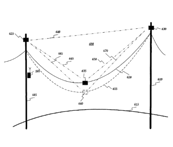
[037] FIG. 6 shows an operating environment 600. As shown in FIG.
6, operating environment 600 may include a first structure 605, a second
structure 610, a ground 615, and a span of conductor in a first position 620
11
CA 02878674 2015-01-06
WO 2014/011760
PCT/1JS2013/049908
above ground 615. Operating environment 600 may include a plurality of
sag transceivers comprising, for example, a first sag transceiver 625, a
second sag transceiver 630, and a third sag transceiver 635. The plurality of
sag transceivers may be included in the plurality of status transducers of
FIG. 2. First sag transceiver 625 may be disposed on first structure 605 and
second sag transceiver 630 may be disposed on second structure 610.
Third sag transceiver 635 may be disposed on the span of conductor, for
example, substantially in the middle or at substantially the low point of sag
of
the span of conductor. Power line monitor 105 may be disposed, for
example, on either of first structure 605 or second structure 610.
[038] First sag transceiver 625 and second sag transceiver 630 may
be disposed a first distance 640 apart, first sag transceiver 625 and third
sag
transceiver 635 may be disposed a second distance 645 apart, and second
sag transceiver 630 and third sag transceiver 635 may be disposed a third
distance 650 apart. As the amount of sag increases or decreases in the
span of conductor, the distance between the span of conductor and ground
615 changes. The amount of sag may increase or decrease in the span of
conductor for any number of reasons including, for example, a change in
ambient temperature, a changes in the temperature of the conductor, icing
in the conductor, etc.
[039] As shown in FIG. 6, the amount of sag may increase in the
span. In this case, the conductor may move from first position 620 to a
second position 655. This change in the conductor's position may cause
third sag transceiver 635 to move to a third sag transceiver second positions
660. Consequently, first sag transceiver 625 and third sag transceiver 635
12
CA 02878674 2015-01-06
WO 2014/011760
PCMJS2013/049908
may now be disposed a fourth distance 665 apart and second sag
transceiver 630 and third sag transceiver 635 may now be disposed a fifth
distance 670 apart.
[040] In order to determine their distances apart, ones of the plurality
of sag transceivers may transmit signals amongst themselves. For example,
first sag transceiver 625, second sag transceiver 630, and third sag
transceiver 635 may have internal synchronized clocks. First sag
transceiver 625 may send a signal to third sag transceiver 635. This signal
may include a time-stamp indicating the time when the signal left first sag
transceiver 625. Third sag transceiver 635 may note the time that the signal
was received from first sag transceiver 625. From the time stamp and the
time the signal was received, third sag transceiver 635 may calculate the
time it took for the signal to travel from first sag transceiver 625 to third
sag
transceiver 635. Third sag transceiver 635 may calculate the distance by
knowing the speed of the signal and the amount of time it took the signal to
get to third sag transceiver 635. This same process may be used between
any of the plurality of sag transceivers to calculate first distance 640,
second
distance 645, third distance 650, fourth distance 665, and fifth distance 670.
Furthermore this calculated distance may be communicated (e.g., over the
network) amongst the plurality of sag transceivers, to power line monitor
105, and to SCADA system 400.
[041] Once the distances between the plurality of sag transceivers is
known, any of the plurality of sag transceivers, power line monitor 105, or
SCADA system 400 can calculate a location of a point on the span of
conductor associated with third sag transceiver 635. In calculating the
13
CA 02878674 2015-01-06
WO 2014/011760
PCMJS2013/049908
location, mathematical processes including, for example, triangulation and
the side-side-side theorem of geometry may be used. Embodiments of the
invention may be calibrated a baseline data. The baseline data may include
a distance (e.g., clearance) between ground 615 for a given location of the
point on the span of conductor associated with third sag transceiver 635.
Then, as this point moves per location recalculations as the sag increase or
decreases, the baseline data may be used to recalculate the clearance
between ground 615 and the span of conductor. If this clearance is too
small as compared to a predetermined value, embodiments of the invention
may provide an alert. Safety codes may be considered when setting this
predetermined value.
[042] FIG. 7 shows an operating environment 700. As shown in FIG.
7, operating environment 700 may include one or more inclinometers (e.g., a
first inclinometer 705, a second inclinometer 710, and a third inclinometer
715) rather than the plurality of sag transceivers of FIG. 6. The
inclinometers, power line monitor 105, or SCADA system 400 may
communicate data amongst each other over, for example, the network. The
one or more inclinometers may be included in the plurality of status
transducers of FIG. 2.
[043] Any one of the inclinometers can provide an angle of a section
of the span of conductor associated with the inclinometer. Embodiments of
the invention may be calibrated with baseline data. The baseline data may
include a distance (e.g., clearance) between ground 615 and a low point of
sag on the span of conductor for a given angle indicated by any of the
inclinometers. As the angle indicated by any of the inclinometers changes
14
CA 02878674 2015-01-06
WO 2014/011760
PCT/1JS2013/049908
as the sag in the span of conductor increases or decreases from the
baseline, the ground clearance distance between ground 615 and a low
point of sag on the span of conductor may be recalculated. This
recalculation may be performed, for example, by the inclinometers, power
line monitor 105, or SCADA system 400. If this clearance is too small as
compared to a predetermined value, embodiments of the invention may
provide an alert. Safety codes may be considered when setting this
predetermined value.
[044] From stage 510, where power line monitor 105 collects the
.. plurality of status data, method 500 may advance to stage 520 where power
line monitor 105 (or SCADA 400) may analyze the collected plurality of
status data to determine when a one of the collected plurality of status data
is outside of a normal operation range for a one of the plurality of
components corresponding to the one of the collected plurality of status
data. Consistent with embodiments of the invention, the collected plurality
of status data may be trended and interpreted. This may include, but is not
limited to, providing: i) trending of component data; ii) heuristic algorithms
specific to each monitored component type, which may interpret real-time
and trended data to determine if the component is degrading; and iii)
comparison of algorithm outputs to alarm set points to determine estimation
of effects of conditions on remaining component life.
[045] For example, conductor splices and conductor dead-ends may
deteriorate over time and may eventually fail. As they approach their failure
point, they become hotter and hotter. Consequently, the temperature of
conductor splice 125 and/or the conductor deadened may be compared to
CA 02878674 2015-01-06
WO 2014/011760
PCT/1JS2013/049908
the temperature of conductor 110. If the temperature of conductor splice
125 and/or the temperature of the conductor deadened is greater than the
temperature of conductor 110 by a predetermined amount, then the
temperature of conductor splice 125 and/or the temperature of the
conductor deadened may be considered to be out side of the normal
operation range for conductor splice 125 and/or the conductor deadened.
[046] As another example, conductor 110 may be prone to
"galloping." Conductor galloping (sometimes called dancing), is a
phenomenon where power line conductors move with large amplitudes.
Galloping usually occurs when an unsteady, high or gusty wind blows over a
conductor covered by a layer of ice deposited by freezing rain, mist, or
sleet.
The coating may vary from a very thin glaze on one side to a solid three-
inch cover giving the conductor an irregularly shaped profile. Consequently,
this ice covering may give the conductor a slightly out-of-round, elliptical,
or
quasi-airfoil shape. Wind blowing over this irregularly shaped profile results
in aerodynamic lift that causes the conductor to gallop. The wind can be
anything between 5 to 45 miles-per-hour at an angle to the power line of 10
to 90 degrees. The wind may be unsteady in velocity or direction.
Consequently, the movement profile of conductor 110 may be periodically
analyzed by conductor motion transducer 245, power line monitor 105, or
SCADA 400 to see if the motion of conductor 110 is consistent with the
galloping conductor phenomenon.
[047] As another example, conductor 110 may be prone to damage
through Aeolian vibration. Aeolian vibration is a high-frequency low-
amplitude oscillation generated by a low velocity, comparatively steady wind
16
CA 02878674 2015-01-06
WO 2014/011760
PCT/1JS2013/049908
blowing across a conductor. This steady wind creates air vortices or eddies
on the lee side of the conductor. These vortices or eddies will detach at
regular intervals from the top and bottom area of the conductor (i.e., "vortex
shedding") creating a force on the conductor that is alternately impressed
from above and below. If the frequency of the forces (i.e., expected
excitation frequency) approximately corresponds to a frequency of a
resonant vibration mode for a conductor span (i.e., natural frequency of the
power line), the conductor will tend to vibrate in many loops in a vertical
plane. The frequency of resonant vibration depends mainly on conductor
size and wind velocity and is generally between 5 and 100 Hz for wind
speeds within the range of 0 to 15 miles per hour. The peak-to-peak
vibration amplitudes will cause alternating bending stresses great enough to
produce fatigue failure in the conductor strands at the attachment points to
the power line structure. Tensioned conductors in long spans are
particularly subject to vibration fatigue. This vibration is generally more
severe in flat open terrain where steady winds are more often encountered.
Consequently, the vibration profile of conductor 110 may be periodically
analyzed by conductor vibration transducer 250, power line monitor 105, or
SCADA 400 to see if the vibration of conductor 110 is greater than
acceptable levels or significantly different than a vibration profile taken at
a
previous time (e.g., when the power line including structure 102 was first
constructed).
[048] Insulator string 115 may be connected to structure 102 on
insulator string support 120. Insulator string support 120, however, may
weaken and loosen due to vibration. Damage to insulator string support 120
17
CA 02878674 2015-01-06
WO 2014/011760
PCT/1JS2013/049908
may be detectable through vibration or excessive motion. Consequently, the
vibration profile of insulator string support 120 may be periodically analyzed
by support vibration transducer 255, power line monitor 105, or SCADA 400
to see if the vibration of insulator string support 120 is greater than
acceptable levels or significantly different than a vibration profile taken at
a
previous time (e.g., when the power line including structure 102 was first
constructed).
[049] Power line structures (e.g., structure 102), for example, may
be made of concrete, wood, or steel. Regardless of the material, power line
structures may deteriorate, for example, by rot, rust, corrode, or the bolts
of
a lattice structure may loosen. A level of deterioration can be determined by
how structure 102 vibrates. Consequently, the vibration profile of structure
102 may be periodically analyzed by structure vibration transducer 260,
power line monitor 105, or SCADA 400 to see if the vibration of structure
102 is greater than acceptable levels or significantly different than a
vibration profile taken at a previous time (e.g., when the power line
including
structure 102 was first constructed).
[050] Structure 102 may be grounded through structure ground 130.
Structure ground 130 may comprise a ground rod or a series of ground rods
being driven into the earth near structure 102. The ground rod or a series of
ground rods are connect to structure 102 by a wire. While an impedance of
structure ground 130 may have been checked and found acceptable (e.g.,
between 20 ohms and 40 ohms) when structure 102 was built, the
grounding of structure 102 may deteriorate overtime. Consequently, the
impedance of structure ground 130 may be periodically analyzed by
18
CA 02878674 2015-01-06
WO 2014/011760
PCT/1JS2013/049908
structure ground transducer 265, power line monitor 105, or SCADA 400 to
see if the impedance of structure ground 130 is greater than a
predetermined acceptable level or significantly different than an impedance
of structure ground 130 taken at a previous time (e.g., when the power line
including structure 102 was first constructed).
[051] With power lines, conductors may be supported or terminated
(e.g., dead-end) at structures where conductors may be electrical isolation
via insulator strings. Insulator strings (e.g., insulator string 115) may fail
either mechanically or electrically. Mechanical failures may be the result of
physical damage to the "bells" or "core" of insulator string 115. Electrical
failures may be the result of contamination and tracking that can be
detected via corona or electromagnetic disruptions (e.g., like static on an AM
radio). Accordingly, embodiments of the invention may use devices that
measure corona or partial discharge that may detect insulator tracking.
Consequently, the electromagnetic profile of insulator string 115 may be
periodically analyzed by insulator electromagnetic transducer 270, power
line monitor 105, or SCADA 400 to see if the corona or electromagnetic
disruptions of insulator string 115 is greater than acceptable levels or
significantly different than an electromagnetic profile taken at a previous
time (e.g., when the power line including structure 102 was first
constructed).
[052] Once power line monitor 105 (or SCADA 400) analyzes the
collected plurality of status data in stage 520, method 500 may continue to
stage 530 where power line monitor 105 (or SCADA 400) may display
results of the collected data analysis. The results may indicate that the one
19
CA 02878674 2015-01-06
WO 2014/011760
PCT/1JS2013/049908
of the collected plurality of status data is outside of the normal operation
range for the one of the plurality of components corresponding to the one of
the collected plurality of status data as described above. For example, if
embodiments of the invention show that sag is increasing beyond that
expected for the electrical load on the conductor and that the weather
conditions are present for ice, then the analysis may indicate that ice
loading
conditions may be present on the power line causing the sag. If however,
the sag is increasing beyond that expected for the electrical load on the
conductor and the weather conditions are not present for ice, then the
analysis may indicate that some other condition is present that is causing
the excessive sag. Furthermore, the display may show a profile of a given
span of conductor. On this profile, two horizontal lines may respectively
indicate an upper safe limit and a lower safe limit of the sag. After power
line monitor 105 displays the results at stage 530, method 500 may then end
at stage 540.
[053] Embodiment of the present invention may, for example, be
implemented using a memory, a processing unit, and other components.
Any suitable combination of hardware, software, and/or firmware may be
used to implement the memory, processing unit, or other components. The
processing unit may implement program modules. Generally, consistent with
embodiments of the invention, program modules may include routines,
programs, components, data structures, and other types of structures that
perform particular tasks or implement particular abstract data types.
[054] Moreover, embodiments of the invention may be practiced with
other computer system configurations, including hand-held devices,
CA 02878674 2015-01-06
WO 2014/011760
PCMJS2013/049908
multiprocessor systems, microprocessor-based or programmable consumer
electronics, minicomputers, mainframe computers, and the like.
Embodiments of the invention may also be practiced in distributed
computing environments where tasks are performed by remote processing
devices that are linked through a communications network. In a distributed
computing environment, program modules may be located in both local and
remote memory storage devices.
[055] Furthermore, embodiments of the invention may be practiced
in an electrical circuit comprising discrete electronic elements, packaged or
integrated electronic chips containing logic gates, a circuit utilizing a
microprocessor, or on a single chip containing electronic elements or
microprocessors. Embodiments of the invention may also be practiced
using other technologies capable of performing logical operations such as,
for example, AND, OR, and NOT, including but not limited to mechanical,
optical, fluidic, and quantum technologies. In addition, embodiments of the
invention may be practiced within a general purpose computer or in any
other circuits or systems.
[056] Embodiments of the invention, for example, may be
implemented as a computer process (method), a computing system, or as
an article of manufacture, such as a computer program product or computer
readable media. The computer program product may be a computer
storage media readable by a computer system and encoding a computer
program of instructions for executing a computer process. The computer
program product may also be a propagated signal on a carrier readable by a
computing system and encoding a computer program of instructions for
21
CA 02878674 2015-01-06
WO 2014/011760
PCMJS2013/049908
executing a computer process. Accordingly, the present invention may be
embodied in hardware and/or in software (including firmware, resident
software, micro-code, etc.). In other words, embodiments of the present
invention may take the form of a computer program product on a computer-
usable or computer-readable storage medium having computer-usable or
computer-readable program code embodied in the medium for use by or in
connection with an instruction execution system. A computer-usable or
computer-readable medium may be any medium that can contain, store,
communicate, propagate, or transport the program for use by or in
.. connection with the instruction execution system, apparatus, or device.
[057] The computer-usable or computer-readable medium may be,
for example but not limited to, an electronic, magnetic, optical,
electromagnetic, infrared, or semiconductor system, apparatus, device, or
propagation medium. More specific examples (a non-exhaustive list) of the
computer-readable medium would include the following: an electrical
connection having one or more wires, a portable computer diskette, a
random access memory (RAM), a read-only memory (ROM), an erasable
programmable read-only memory (EPROM or Flash memory), an optical
fiber, and a portable compact disc read-only memory (CD-ROM). Note that
the computer-usable or computer-readable medium could even be paper or
another suitable medium upon which the program is printed, as the program
can be electronically captured, via, for instance, optical scanning of the
paper or other medium, then compiled, interpreted, or otherwise processed
in a suitable manner, if necessary, and then stored in a computer memory.
22
CA 02878674 2015-01-06
WO 2014/011760
PCMJS2013/049908
[058] Embodiments of the present invention are described above
with reference to block diagrams and/or operational illustrations of methods,
systems, and computer program products according to embodiments of the
invention. It is to be understood that the functions/acts noted in the blocks
may occur out of the order noted in the operational illustrations. For
example, two blocks shown in succession may in fact be executed
substantially concurrently or the blocks may sometimes be executed in the
reverse order, depending upon the functionality/acts involved.
[059] While certain features and embodiments of the invention have
been described, other embodiments of the invention may exist.
Furthermore, although embodiments of the present invention have been
described as being associated with data stored in memory and other storage
mediums, aspects can also be stored on or read from other types of
computer-readable media, such as secondary storage devices, like hard
disks, floppy disks, or a CD-ROM, a carrier wave from the Internet, or other
forms of RAM or ROM. Further, the steps of the disclosed methods may be
modified in any manner, including by reordering stages and/or inserting or
deleting stages, without departing from the principles of the invention.
[060] While certain embodiments of the invention have been
described, other embodiments may exist. While the specification includes
examples, the invention's scope is indicated by the following claims.
Furthermore, while the specification has been described in language specific
to structural features and/or methodological acts, the claims are not limited
to the features or acts described above. Rather, the specific features and
acts described above are disclosed as example for embodiments of the
23
CA 02878674 2015-01-06
WO 2014/011760
PCT/1JS2013/049908
invention.
24