Note: Descriptions are shown in the official language in which they were submitted.
CA 2878677 2017-04-19
[0001]TITLE: PACKER SETTING AND/OR UNSETTING
BACKGROUND
[0005]Technical Field: Oilfield operations may be performed in order to
extract
fluids from the earth (including subsea). When a well site is completed,
pressure control equipment may be placed near the surface of the earth. The
pressure control equipment may control the pressure in the wellbore while
drilling, completing and producing the wellbore. The pressure control
equipment may include blowout preventers (BOP), rotating control devices
(ROD), and the like.
[0006]The rotating control device or RCD is a drill-through device with a
rotating
seal that contacts and seals against the drill string (drill pipe, casing,
drill collars,
Kelly, etc.) for the purposes of controlling the pressure or fluid flow
1
CA 2878677 2017-04-19
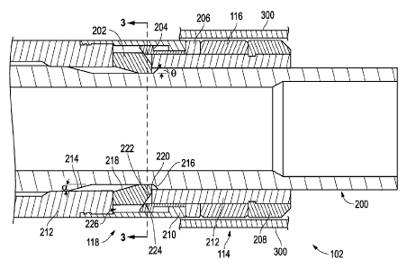
to the surface. For reference to an existing descriptions of a rotating
control
device incorporating a system for sealing a marine riser having a rotatable
tubular, please see US patent number 8,322,432 entitled "Subsea Internal
Riser Rotating Control Device System and Method", U.S. Application no.
12/643,093, filed December 21, 2009 and published July 15, 2010; and US
patent publication number US 2012/0318496 entitled "Subsea Internal Riser
Rotating Control Head Seal Assembly", U.S. Application no. 13/597,881, filed
August 29, 2012 and published December 20, 2012.
These publications describe a rotating
control device having a seal assembly to seal the RCD with the riser.
[0007] Conventional sealing systems for RCD's include a drill string sealing
element which seals against the rotating drill string and several external
seals
which seal against a fixed flanged housing. The flanged housing is part of
stackup below the rig. The RCD external housing is held fixed to the flanged
housing by hydraulic or mechanical means. Downhole pressure is contained
via the internal drill string sealing element and the external static seals on
the
housing.
[0008]Conventional packers have external sealing elements that are
hydraulically set via downhole pressure. The packer sealing element is held in
the set position via a body lock ring. Pressure below the packer is contained
via the packer element sealing against the casing. To unset the packer the
housing lock ring is released via a shear ring and a collet by pulling up or
setting down load on the packer. Conventional packers can only be set and
unset once and then they have to be pulled out of the hole for redress due to
the shear ring use.
[0009] Since packer elements are elastomers and have limited use they have
to be replaced periodically making it very costly or impossible to retrieve
from,
for example, a flanged housing, subsea riser, or casing. A need exists for a
seal system that can be set and retrieved with the RCD instead of being part
of the permanent or semi-permanent components (e.g. flanged housing,
subsea riser or casing).
2
CA 02878677 2015-01-08
WO 2014/012056
PCT/US2013/050371
BRIEF SUMMARY OF THE EMBODIMENT(S)
[0010]This seal system uses a packer type sealing element in one
embodiment on the external housing of a RCD however it is set and unset
mechanically instead of hydraulically. The RCD can therefore be set
anywhere there is a locking profile, e.g. flanged housing (in a stackup rig
configuration), subsea riser or in casing.
[0011]In this embodiment the RCD housing has external biased out latch
locking dogs that engage a profile in the flanged housing, riser or casing.
Once the latch locking dogs engage the profile the RCD housing is locked in
place from moving further downhole. The mandrel inside the RCD housing is
locked to the drill string via mechanical means. As the drill string is
lowered
the mandrel pushes out a different set of dogs that push against the packer
housing which sets the packer(s). Now the downhole pressure is held in place
by the drill string sealing element and the external packer(s) on the RCD
housing. To unset the packer(s) the translating mandrel is pulled up and the
stored energy of the packer(s) will push the packer housing and therefore the
dogs back in radially.
[0012]Advantages of this system are that the packer(s) can be set and unset
multiple times as long as the packer(s) is not damaged; the packer(s) can be
easily replaced and then reinstalled; and/or the packer(s) can be deployed in
a subsea RCD.
[0013] Accordingly, linear movement via a sliding mandrel configured to
translate axially is converted into radial movement to compress a packer. The
packer is configured to seal an item of oilfield equipment typically in a
subsea
environment. The packer may also be used to return or reverse the radial
movement and/or the linear movement.
[0014]As used herein the terms "radial" and "radially" include directions
inward toward (or outward away from) the center axial direction of the drill
string or item of oilfield equipment but not limited to directions
perpendicular to
such axial direction or running directly through the center. Rather such
3
CA 02878677 2015-01-08
WO 2014/012056
PCT/US2013/050371
directions, although including perpendicular and toward (or away from) the
center, also include those transverse and/or off center yet moving inward (or
outward), across or against the surface of an outer sleeve of item of oilfield
equipment to be engaged.
BRIEF DESCRIPTION OF THE SEVERAL VIEWS OF THE DRAWINGS
[0015]Figure 1 depicts a schematic view of a wellsite.
Figure 2 depicts a longitudinal cross sectional view of the housing or a
running in position having the seal system according to an
embodiment.
Figure 3 depicts a top cross section view or running in position of the
seal system taken through the dogs.
Figure 4 depicts a longitudinal cross section view or partial setting
sequence of the seal system prior to actuation of the seal.
Figure 5 depicts a longitudinal cross section of the seal system in an
intermediate position between the unactuated and actuated position or
during the setting sequence.
Figure 6 depicts a longitudinal cross section of the seal system in an
actuated or set position.
Figure 7 depicts top cross section view of the seal system in the
actuated or set position taken through the dogs.
Figure 8 depicts a method of using the seal system.
DETAILED DESCRIPTION OF THE EMBODIMENT(S)
[0016]The description that follows includes exemplary apparatus, methods,
techniques, and instruction sequences that embody techniques of the
inventive subject matter. However, it is understood that the described
embodiments may be practiced without these specific details.
[0017] Figure 1 depicts a schematic view of a wellsite 100 with a rig 101. The
wellsite 100 has a seal system 102 for sealing to an item or piece of oilfield
4
CA 02878677 2015-01-08
WO 2014/012056
PCT/US2013/050371
equipment 104. As shown, the wellsite 100 is an offshore wellsite although
other types of wellsites are applicable. The wellsite 100 may have a wellbore
106 formed in the sea floor 108 and lined with a casing 110. At the sea floor
108 one or more pressure control devices 112 may control pressure in the
wellbore 106. The pressure control devices 112 may include, but are not
limited to, BOPs, RCDs 113, and the like. The seal system 102 is shown and
described herein as being located in a housing 114. The seal system 102 may
have one or more seal member(s)/packer(s) 116 configured to engage the
oilfield equipment 104. The seal system 102 may have one or more actuators
118 configured to drive the seal member 116 into and out of engagement with
the oilfield equipment 104. The seal system 102 may set and unset the seal
member 116 via mechanical movement of a mandrel as will be discussed in
more detail below. The oilfield equipment 104 may be any suitable equipment
that will be sealed with the seal system 102 including, but not limited to,
the
RCD 113, a drill string, a casing, a production tubing, a sleeve, and the
like.
The seal system 102 may further include one or more sensors 119 configured
to identify the status of the seal system 102 and/or to inform the controller
120
that the packer 116 is sealed, not sealed, and/or at an intermediate position.
The seal system 102, for example, may be incorporated with a subsea RCD
113 and used for sealing against a riser 300 (Fig. 6).
[0018]The wellsite 100 may have a controller 120 for controlling the seal
system 102. In addition to controlling the seal system 102, the controller
120,
and/or additional controllers (not shown), may control and/or obtain
information from any suitable system about the wellsite 100 including, but not
limited to, the pressure control devices 112, the housing 114, the sensor(s)
119, a gripping apparatus 122, a rotational apparatus 124, and the like. As
shown, the gripping apparatus 122 may be a pair of slips configured to grip a
tubular 125 (such as a drill string, a production string, a casing and the
like) at
a rig floor 126; however, the gripping apparatus 122 may be any suitable
gripping device. As shown, the rotational apparatus 124 is a top drive for
supporting and rotating the tubular 125, although it may be any suitable
rotational device including, but not limited to, a Kelly, a pipe spinner, and
the
CA 02878677 2015-01-08
WO 2014/012056
PCT/US2013/050371
like. The controller 120 may control any suitable equipment about the wellsite
100 including, but not limited to, a draw works, a traveling block, pumps, mud
control devices, cementing tools, drilling tools, and the like.
[0019]Figure 2 depicts a longitudinal cross sectional view of the housing 114
having the seal system 102 according to an embodiment. The housing 114,
as shown, has the seal member or packer 116 (in the unset position, i.e. not
opposing or sealing against the flanged housing, casing or subsea riser 300)
and the one or more actuators 118.The actuator 118 (which may for example
be mounted below the RCD 113 body) may include, but is not limited to, a
sliding mandrel 200, a dog 202, a sliding sleeve 204, a packer ring 206, an
engagement portion 208, an outer sleeve 210, and a stationary mandrel, tool
body, or stationary housing 212. The actuator 118 may be configured to set
and unset the sealing member or packer 116 via axial movement of the sliding
mandrel 200. The axial translation of the sliding mandrel 200 may convert the
axial movement into radial movement via the dog 202. The dog 202 may then
convert the radial translation back into axial movement via the sliding sleeve
204. The sliding sleeve 204 may engage the packer ring 206 and thereby
compress the packer 116 in order to set the packer 116 as will be discussed
in more detail below.
[0020]The sealing member or packer 116 may be any suitable deformable
packer sealing member including, but not limited to an elastomeric member,
and the like, configured to expand radially outward upon axial compression of
the sealing member 116.
[0021]The sliding mandrel 200 may have a setting surface 214 configured to
engage the dog 202 in order to set and unset the packer 116. As shown, the
setting surface 214 is located in a profile formed in an outer surface of the
sliding mandrel 200. The setting surface 214 may be configured to engage a
dog setting surface 218. As the setting surface 214 engages the dog setting
surface 218, the continual axial movement in the setting direction of the
sliding mandrel 200 forces the dog 202 to translate radially outward, or away
from the sliding mandrel 200. When unsetting the packer 116, the sliding
6
CA 02878677 2015-01-08
WO 2014/012056
PCT/US2013/050371
mandrel 200 may be moved in the opposite direction, or unsetting direction.
Once the setting surface 214 disengages the dog setting surface 218, the
stored energy in the packer 116 may force the packer ring 206 and thereby
the sliding sleeve 204 to release and/or unset the packer 116.
[0022]The sliding mandrel 200 may move in the unset and setting direction
via mechanical manipulation of the sliding mandrel 200 from the rig 101 or
drill
string. Further, the sliding mandrel 200 may move via hydraulic, electric,
pneumatic power and the like.
[0023] The setting surface 214 may have a relatively small angle a configured
to engage the dog setting surface 218 having a similar angle as a. The small
angle a allows relatively large translations of the sliding mandrel 200 to
translate into small outward radial movement of the dog 202. This small radial
movement of the dog 202 may gradually set the packer 116 by gradually
moving the sliding sleeve 204.
[0024] Opposite the setting surface 214 may be a secondary setting surface
216. The secondary setting surface 216 may have a larger or steeper angle 0
than the small angle a. The larger angle 0 of the secondary setting surface
216 may engage a dog secondary setting surface 220. The larger angle may
move the dog 202 radially away from the sliding mandrel 200 at a faster rate
per axial translation of the sliding mandrel 200 than the setting surface.
Therefore, the operator may relatively more slowly engage and/or set the
packer 116 by moving the sliding mandrel 200 in the setting direction
(downhole) and then may relatively more quickly release the packer 116 by
moving the sliding mandrel in the unsetting direction with the secondary
setting surface 216 engage in the dog secondary setting surface 220.
[0025] In an alternative embodiment, the secondary setting surface 216 may
be a shoulder configured to engage the dog 202 thereby stopping travel of the
sliding mandrel 200.
[0026] In an alternative embodiment the secondary setting surface 216 can
be angled in an opposite direction (not shown) arranged in order to pull the
7
CA 02878677 2015-01-08
WO 2014/012056
PCT/US2013/050371
dog(s) 202 radially inward. In this embodiment, the dog(s) 202 could also
positively pull the sliding sleeve 204 toward the disengagement position.
[0027]There may be one or multiple dogs 202 located around the sliding
mandrel 200. As shown there are multiple dogs 202 which travel radially
though one or more slots 226 in the stationary mandrel 212. Although not
shown, the dog 202 may be biased radially inward, or toward the unset
position.
[0028]The dog 202 may have a dog actuation surface 222 configured to a
sleeve actuation surface 224 on the sliding sleeve 204. As the dog 202 travels
radially away from the sliding mandrel 200 the dog actuation surface 222
engages the sleeve actuation surface 224. Continued radial movement of the
dog 202 outward moves the sliding sleeve 204 toward the packer ring 206
due to the interaction between the dog actuation surface 222 and the sleeve
actuation surface 224. Although not shown, the dog 202 may be biased
radially inward, or toward the unset position.
[0029] In an alternative embodiment, the dog actuation surface 222 may be
locked to the sleeve actuation surface 224 for example with a dove tail
configuration in order to positively move the sliding sleeve 204 both toward
and away from the packer ring 206.
[0030] The sliding sleeve 204 may travel through an aperture formed
between the outer sleeve 210 and the stationary mandrel 212. A nose 228 of
the sliding sleeve 204 engages the packer ring 206 as the dog(s) 202 actuate
the sliding sleeve 204. The sliding sleeve 204 then moves the packer ring 206
toward the packer 116 thereby compressing the packer 116 into an actuated
position. There may be one annular sliding sleeve 204 or multiple sliding
sleeves 204 for each of the dogs 202.
[0031] The packer ring 206 may be a full ring around the proximate the packer
116, or may be a partial ring. Further, there may be a second packer ring
206a (see Fig. 4) located on the opposite side of the packer 116. The second
8
CA 02878677 2015-01-08
WO 2014/012056
PCT/US2013/050371
packer ring 206a may distribute the compression force on the packer 116
from the sliding sleeve 204.
[0032] Figure 3 depicts a top cross section view of the seal system 102 taken
through the dogs 202. As shown, the seal system 102 is in the unactuated, or
run in, position. In the run in position, the setting surface 214 and/or the
secondary setting surface 216 (as shown in Figure 2) have not moved the
dogs 202 toward the sliding sleeve 204. As shown, there are four dogs 202
configured to move through the slots 226 in the stationary housing 212. In the
run in position, the packer 116 may be moved to a location to be sealed. For
example, the packer 116 may be moved into the RCD 113 (as shown, in
Figure 1) or any other suitable location including, but not limited to, in the
wellbore 106, the casing 110, and the like.
[0033] Figure 4 depicts a longitudinal cross section view of the seal system
102 when the sliding mandrel 200 initially engages the dogs 202 and the
packer 116 is still unactuated. As shown, the sliding mandrel 200 has been
moved relative to the stationary housing 212 until the setting surface 214
engages the dog setting surface 218.
[0034] Figure 5 depicts a longitudinal cross section of the seal system 102 in
an intermediate position between the unactuated and actuated position. In this
position, the setting surface 214 has moved the dog(s) 202 radially outward
due to continued axial movement of the sliding mandrel 200. The dog
actuation surface 222 has engaged the sleeve actuation surface 224 thereby
moving the nose 228 of the sliding sleeve 204 into engagement with the
packer ring 206. The packer ring 206 may be compressing the packer 116 in
this position, but the packer 116 may not be fully actuated.
[0035] Figure 6 depicts a longitudinal cross section of the seal system 102 in
an actuated position. The continued movement of the sliding mandrel 200 has
moved the dog(s) 202 and thereby the packer 116 into an actuated, or sealed,
position. As shown, the setting surface 214 has moved the dog(s) 202 to a
position outside of an outer surface 600 of the sliding mandrel 200. The dog
actuation surface 222 has moved the sliding sleeve 204 to an actuated
9
CA 02878677 2015-01-08
WO 2014/012056
PCT/US2013/050371
position. In the actuated position, the packer ring 206 may have moved
longitudinally toward the packer 116 thereby compressing the packer 116.
The compression of the packer 116 may extend the packer 116 radially
outward into a sealed or actuated position against a casing or subsea riser
300. As shown, the outer sleeve 210 may limit the radial movement of the
dog(s) 202. Further, a sliding mandrel shoulder 601 may engage a limit
shoulder 602 of the stationary housing 212 in order to limit the movement of
the sliding mandrel 200 (e.g. to prevent the sliding mandrel 200 from moving
further downhole). Any downhole pressure from below the packer 116 is
translated back to the dog(s) 202 and applies a collapse load against the
outer surface 600 of the sliding mandrel 200.
[0036] Figure 7 depicts top cross section view of the seal system 102 in the
actuated position taken through the dogs 202. As shown, the dog(s) 202 are
shown radially outside of the sliding mandrel 200.
[0037] The seal system 102 may remain in the actuated position until it is
desired to remove the seal system 102. To remove the seal system 102, the
sliding mandrel may be moved in the opposite axial direction to the actuation
direction. When the sliding mandrel 200 reaches a position wherein the
setting surface 214 is in longitudinal alignment with the dogs 202, the stored
energy in the packer 116 may push the packer ring 206, the sliding sleeve
204 and the dog(s) 202 toward the unactuated position.
[0038] Figure 8 is a flow chart depicting a method of sealing an item of
oilfield
equipment. The flow starts at block 800 wherein, the seal system is located
proximate a piece of oilfield equipment. The flow continues at block 802
wherein, the sliding mandrel 200 is translated axially relative to the tool
body
of the seal system. The sliding mandrel 200 may be translated using
mechanical actuation as discussed above. The flow continues at block 804
wherein, the seal member 116 is actuated in response to the translation of the
sliding mandrel 200. The flow continues at block 806 wherein, the item of
oilfield equipment 104 is sealed with the seal member 116. The flow continues
at block 808 wherein, the seal member 116 is removed from the item of
CA 02878677 2015-01-08
WO 2014/012056
PCT/US2013/050371
oilfield equipment 104 by moving the sliding mandrel 200 in the opposite
direction from the direction it moved during actuation.
[0039] While the
embodiments are described with reference to various
implementations and exploitations, it will be understood that these
embodiments are illustrative and that the scope of the inventive subject
matter
is not limited to them. Many
variations, modifications, additions and
improvements are possible. For example,
the implementations and
techniques used herein may be applied to any seal system at the wellsite,
such as the downhole packer, and the like.
[0040] Plural
instances may be provided for components, operations or
structures described herein as a single instance. In general, structures and
functionality presented as separate components in the exemplary
configurations may be implemented as a combined structure or component.
Similarly, structures and functionality presented as a single component may
be implemented as separate components. These and other variations,
modifications, additions, and improvements may fall within the scope of the
inventive subject matter.
11