Note: Descriptions are shown in the official language in which they were submitted.
CA 02878821 2015-01-09
1
DESCRIPTION
ELECTRODE CATHETER AND METHOD FOR MANUFACTURING
THE SAME
Technical Field
[0001] The present invention relates to an electrode catheter provided with
a tip electrode.
Background Art
[0002]
Electrode catheters are known as medical devices used for
diagnosing or treating irregular heartbeats of heart.
As an electrode catheter for measuring potential in a portion such as a
pulmonary vein of heart, the present applicant has proposed an electrode
catheter having a catheter shaft, an operating handle connected to a base end
side of the catheter shaft, a catheter tip part formed in a circular loop
shape
connected to a tip side of the catheter shaft, plural ring-shaped electrodes
attached to an outer periphery of the catheter tip part, and a tip electrode
attached to a tip of the catheter tip side (see Patent Document 1).
[0003] The
catheter shaft (catheter main body) constituting the electrode
catheter described in Patent Document 1 has a single lumen structure (thin
long tubular structure having one internal hole) having a resin tube (first
tube) with relatively high rigidity and a soft resin tube (second tube) with
relatively low rigidity.
Here, a preferred outside diameter of the catheter shaft is 2.3 to 2.4
mm (see [0021] to [0025] of Patent Document 1).
CA 02878821 2015-01-09
2
[0004] Thus, for example, when plural (for example, two to three) electrode
catheters are passed through one sheath and inserted into a heart so as to
measure intracardiac potentials simultaneously in plural regions, the outside
diameter of the catheter shaft constituting these catheters is desirably
smaller
than an outside diameter which is preferred in Patent Document 1 (for
example, 1.4 mm or less).
[0005] On the other hand, the electrode catheter needs to be changed
in
direction to select a blood vessel which reaches the target region, or needs
to
bend the tip portion of the catheter shaft largely when the electrode is
pressed
against the target position. Thus, the catheter shaft constituting the
electrode
catheter is required to have good kink resistance and torque transmissibility.
Further, the catheter shaft needs to have a good pushability.
[0006] However, the catheter shaft having a small outside diameter as
described above does not have good kink resistance and torque
transmissibility because it has low rigidity. Further, the catheter shaft
having
a small outside diameter has a poor pushability.
[0007] Moreover, in a catheter shaft having the single lumen structure like
the one constituting the electrode catheter described in Patent Document 1,
lead wires extending inside the shaft and a wire for pulling operation which
moves in an axial direction inside the shaft easily interfere with each other.
Consequently, the lead wires may be damaged or broken. Then, the
interference between the lead wires and the wire occurs more easily in a
catheter shaft with a smaller outside diameter.
Prior Art Document
Patent Document
[0008] Patent Document 1: Japanese Patent Application Laid-open No.
CA 02878821 2015-01-09
3
2008-245767
Summary of the Invention
Problems to be Solved by the Invention
[0009] The present invention has been made based on the situation as
described above.
It is an object of the present invention to provide an electrode catheter
having high operability and having good kink resistance, torque
transmissibility, and pushability in the entire shaft even when its outside
diameter is small.
It is another object of the invention to provide a method for
manufacturing an electrode catheter having high operability and having good
kink resistance, torque transmissibility, and pushability in the entire shaft
even when its outside diameter is small.
Means for Solving the Problem
[0010] (1) An electrode catheter of the present invention has:
a catheter shaft;
an operating handle connected to a base end side of the catheter shaft;
a connector provided in the operating handle;
a tip electrode attached to a tip of the catheter shaft;
a lead wire having its tip connected to the tip electrode, extending
along an axial direction inside the catheter shaft, and having its rear end
connected to the connector; and
a wire having its tip fixed to the tip electrode or a tip portion of the
catheter shaft, extending along the axial direction inside the catheter shaft,
and having its rear end fixed to the operating handle or a base end portion of
CA 02878821 2015-01-09
4
the catheter shaft,
wherein the catheter shaft has:
a shaft proximal end portion formed of a metal tube having a spiral
slit (penetrating slit) formed at least in a tip portion;
a shaft distal end portion formed of a resin tube having a multi-lumen
structure coupled to the shaft proximal end portion by inserting its rear end
portion into a tip portion of the shaft proximal end portion; and
a resin covering layer covering outer peripheries of the shaft proximal
end portion and the rear end portion of the shaft distal end portion, and
wherein the lead wire and the wire extend through different lumens of
the shaft distal end portion.
[0011] In the electrode catheter of such structure, since the shaft proximal
end portion in the catheter shaft is constituted of the metal tube, torque
transmissibility and pushability of the shaft proximal end portion can be
made quite high as compared to the case where it is constituted of a resin
tube.
[0012] On the other hand, the shaft distal end portion of this catheter shaft
is constituted of the resin tube having the multi-lumen structure. The resin
tube having the multi-lumen structure has a higher ratio of resin constituting
the tube than the resin tube having a single lumen structure. Therefore, the
shaft distal end portion constituted of the resin tube having the multi-lumen
structure has sufficiently high operability as compared to one constituted of
the resin tube having the single lumen structure.
[0013]
Thus, even when the outside diameter of the catheter shaft
constituting the electrode catheter is small, the entire shaft including the
shaft
distal end portion has sufficiently high rigidity, and good torque
transmissibility and pushability can be exhibited in the entire shaft.
CA 02878821 2015-01-09
[0014] Further, in the above-described electrode catheter, rigidity of
the
shaft distal end portion constituted of the resin tube is increased by
employing the multi-lumen structure, and rigidity of the shaft proximal end
portion formed of the metal tube is lowered to a certain degree by forming the
5 spiral slit. Thus, despite that the shaft proximal end portion (metal
tube) and
the shaft distal end portion (resin tube) are constituted of materials
different
from each other, rigidity of the catheter shaft does not change excessively
between the shaft proximal end portion and the shaft distal end portion.
Thus, since rigidity does not change excessively (or can be changed
smoothly) between different materials, it is possible to effectively prevent
that stress concentrates between the shaft proximal end portion and the shaft
distal end portion and generates a kink when the catheter shaft is bent.
[0015] Further, in the above-described electrode catheter, by inserting the
rear end portion of the shaft distal end portion into the tip portion of the
shaft
proximal end portion to thereby couple them, the width of the slit formed in
the shaft proximal end portion can be widen easily in a coupling portion. By
widening the slit width in the coupling portion, rigidity in this coupling
portion can be decreased.
Thus, rigidity in the coupling portion can be adjusted to be lower than
rigidity of the tip portion of the shaft proximal end portion (portion other
than
the coupling portion) and higher than rigidity of the shaft distal end portion
(portion other than the coupling portion), that is, the rigidity decreases
gradually in a direction toward the tip over the entire shaft.
Further, due to that the width of the slit formed in the tip portion of
the shaft proximal end portion is widened in the coupling portion to lower
rigidity of the coupling portion, generation of kink between the coupling
CA 02878821 2015-01-09
6
portion and the shaft distal end portion can be prevented.
[0016] When the tip portion of the shaft proximal end portion
(flexible
deformation part of the base part shaft in which the slit is formed) formed of
a metal tube is inserted into the shaft distal end portion (tip shaft) formed
of a
resin tube to couple them, a slit width of the shaft proximal end portion
cannot be widen in the coupling portion (rigidity in the coupling portion
cannot be lowered), and thus rigidity of the coupling portion becomes highest.
In such a case, adjustment to lower the rigidity in the direction toward the
tip
is not possible.
[0017] Further, in the above-described electrode catheter, due to that the
resin covering layer covering the outer peripheries of the shaft proximal end
portion and the shaft distal end portion is formed, the metal constituting the
shaft proximal end portion can be prevented from contacting blood while this
electrode catheter is used, and liquid tightness of the shaft proximal end
portion in which the slit is formed can be assured.
[0018] Moreover, in the electrode catheter as described above, since
the
lead wire and the wire extend through different lumens of the resin tube
constituting the shaft distal end portion, interference between the lead wire
and the wire can be avoided in the shaft distal end portion. Further, the wire
and the lead wire extending through the different lumens in the shaft distal
end portion are difficult to contact (interfere) also in the shaft proximal
end
portion, and damage or cut of the lead wire due to interference with the wire
can thereby be prevented.
[0019] (2) In the electrode catheter of the present invention, preferably, a
pitch of the slit formed in the shaft proximal end portion narrows
sequentially
or stepwise in a direction toward a tip.
CA 02878821 2015-01-09
7
In the electrode catheter of such structure, rigidity of the shaft
proximal end portion can be decreased sequentially or stepwise in the
direction toward the tip. Thus, a catheter shaft excelling particularly in
operability can be structured.
[0020] (3) In the electrode catheter of the present invention, preferably, an
outside diameter of the catheter shaft is 1.4 mm or less.
In the electrode catheter having such a catheter shaft with a small
outside diameter, it is particularly effective to employ the structure of the
catheter shaft according to the present invention (the coupling structure
between the shaft proximal end portion constituted of the metal tube in which
the spiral slit is formed and the shaft distal end portion constituted of the
resin tube having the multi-lumen structure).
[0021] (4) Preferably, an area ratio of resin constituting the tube is 60% or
more in a transverse sectional view of the shaft distal end portion (resin
tube
having the multi-lumen structure) of the catheter shaft constituting the
electrode catheter of the present invention.
In the resin tube having the multi-lumen structure in which the area
ratio of resin constituting the tube is 60% or more (the sum of area ratios of
the lumens is 40% or less), the shaft distal end portion with sufficiently
high
rigidity can be structured.
[0022] (5) In the electrode catheter of the present invention,
preferably,
(W1/W0) is 1.3 or more, where (W1) represents a width of the slit in the shaft
proximal end portion in a coupling portion to the shaft distal end portion
(portion into which the rear end portion of the shaft distal end portion is
inserted), and (W0) represents a width of the slit of the shaft proximal end
portion in a portion other than the coupling portion.
CA 02878821 2015-01-09
8
In the electrode catheter of such structure, due to that the width of the
slit in the coupling portion is sufficiently widened, rigidity in the coupling
portion can be lowered sufficiently, and generation of kink between the
coupling portion and the shaft distal end portion can be securely prevented.
[0023] (6) In the electrode catheter of the present invention, preferably, a
constituent resin of the shaft distal end portion flows into the slit of the
shaft
proximal end portion in the coupling portion to the shaft distal end portion,
and in particular, the constituent resin of the shaft distal end portion which
flowed into the slit of the shaft proximal end portion is fused onto the resin
covering layer.
In the electrode catheter of such structure, by an anchor effect
(meshing effect) of the slit of the shaft proximal end portion and the resin
which flowed therein, the shaft proximal end portion formed of the metal
tube and the shaft distal end portion formed of the resin tube can be joined
strongly.
[0024] (7) In the electrode catheter of above (6), preferably, the
resin
covering layer is formed by shrinking a heat-shrinkable resin tube in a state
that the shaft proximal end portion and the rear end portion of the shaft
distal
end portion are inserted therein, and a melting point of a heat-shrinkable
resin
constituting the heat-shrinkable resin tube is higher than a melting point of
the resin constituting the shaft distal end portion.
With the electrode catheter of such structure, in a manufacturing step
thereof (step of forming the resin covering layer), by heating the heat-
shrinkable resin tube in a state that the shaft proximal end portion and the
rear end portion of the shaft distal end portion are inserted therein under a
temperature condition equal to or more than a melting point of the resin
CA 02878821 2015-01-09
9
constituting the shaft distal end portion and less than the melting point of
the
heat-shrinkable resin, the heat-shrinkable resin tube shrinks to form the
resin
covering layer, part of the constituent resin of the resin tube to be the
shaft
distal end portion melts, and the constituent resin of the resin tube (molten
resin) can flow into the slit of the shaft proximal end portion in the
coupling
portion to the shaft distal end portion.
[0025] (8) In the electrode catheter of the present invention, preferably, a
rear end of the wire is capable of pulling operation, and the tip of the
catheter
shaft is deflectable by a pulling operation of the rear end of the wire.
[0026] (9) A manufacturing method of the present invention is a method for
manufacturing the electrode catheter of above (7), the method including:
enlarging a diameter of a tip region of the tip portion of the metal tube
constituting the shaft proximal end portion and enlarging a width of the slit
formed in the tip region;
inserting a rear end region of the rear end portion of the resin tube
constituting the shaft distal end portion into the tip region of the metal
tube,
thereby engaging the shaft proximal end portion and the shaft distal end
portion; and
inserting the shaft proximal end portion and the rear end portion of
the shaft distal end portion, which are engaged, into the heat-shrinkable
resin
tube, and thereafter heating the heat-shrinkable resin tube under a
temperature condition equal to or more than the melting point of the resin
constituting the shaft distal end portion and less than the melting point of
the
heat-shrinkable resin to shrink the heat-shrinkable resin tube, to thereby
crimp an engaging portion of the shaft proximal end portion and the shaft
distal end portion to couple the shaft proximal end portion and the shaft
distal
CA 02878821 2015-01-09
end portion, thereby forming the resin covering layer on the outer peripheries
of the shaft proximal end portion and the rear end portion of the shaft distal
end portion which are coupled.
5 Effects of the Invention
[0027] In an electrode catheter of the present invention, even when an
outside diameter of a catheter shaft constituting the electrode catheter is
small,
the entire shaft including a shaft distal end portion has sufficiently high
rigidity, and good kink resistance, torque transmissibility and pushability
can
10 be exhibited in the entire shaft.
Further, in a catheter shaft constituting the electrode catheter of the
present invention, although the shaft proximal end portion is formed of a
metal tube and the shaft distal end portion is formed of a resin tube,
rigidity
does not change excessively between the shaft proximal end portion and the
shaft distal end portion. Thus, generation of kink between the shaft proximal
end portion and the shaft distal end portion can be prevented.
Further, in the electrode catheter of the present invention, even when
an outside diameter of the catheter shaft constituting the electrode catheter
is
small, interference between a lead wire and a wire extending inside the shaft
can be avoided, and damage or cut of the lead wire due to interference with
the wire can be prevented.
[0028] By a manufacturing method of the present invention, it is possible to
manufacture an electrode catheter provided with a catheter shaft having
sufficiently high rigidity and having good kink resistance, torque
transmissibility, and pushability in the entire shaft even when its outside
diameter is small, in which the shaft proximal end portion and the shaft
distal
CA 02878821 2015-01-09
11
end portion are joined firmly.
Brief Description of Drawings
[0029]
Fig. 1 is a vertical sectional view (with a partial plan view)
illustrating an electrode catheter according to one embodiment of the present
invention.
Fig. 2 is a vertical sectional view (detailed sectional view of part A of
Fig. 1) illustrating a shaft proximal end portion of the catheter shaft
constituting the electrode catheter illustrated in Fig. 1.
Fig. 3 is a vertical sectional view (detailed sectional view of part B of
Fig. 1) illustrating a coupling portion between the shaft proximal end portion
and a shaft distal end portion of the catheter shaft constituting the
electrode
catheter illustrated in Fig. 1.
Fig. 4 is a vertical sectional view (detailed sectional view of part C of
Fig. 1) illustrating the shaft distal end portion of the catheter shaft
constituting the electrode catheter illustrated in Fig. 1.
Fig. 5 is a transverse sectional view (D-D sectional view) of the shaft
proximal end portion illustrated in Fig. 2.
Fig. 6 is a transverse sectional view (E-E sectional view) of the
coupling portion illustrated in Fig. 3.
Fig. 7 is a transverse sectional view (F-F sectional view) of the shaft
distal end portion illustrated in Fig. 4.
Fig. 8 is a vertical sectional view for explaining a method for
manufacturing the electrode catheter illustrated in Fig. 1.
Fig. 9 is a vertical sectional view for explaining the method for
manufacturing the electrode catheter illustrated in Fig. 1.
CA 02878821 2015-01-09
12
Fig. 10 is a vertical sectional view (with a partial plan view)
illustrating an electrode catheter according to another embodiment of the
present invention.
Fig. 11 is a vertical sectional view (detailed sectional view of part G
of Fig. 10) illustrating a shaft proximal end portion of a catheter shaft
constituting the electrode catheter illustrated in Fig. 10.
Fig. 12 is a vertical sectional view (detailed sectional view of part H
of Fig. 10) illustrating a coupling portion between the shaft proximal end
portion and a shaft distal end portion of the catheter shaft constituting the
electrode catheter illustrated in Fig. 10.
Fig. 13 is a transverse sectional view (I-I sectional view) of the
coupling portion illustrated in Fig. 12.
Mode for Carrying out the Invention
[0030] <First Embodiment>
An electrode catheter 100 of this embodiment illustrated in Fig. 1 to
Fig. 7 is, for example, used for measuring potential in a region of a
pulmonary vein of heart, or the like.
[0031] This electrode catheter 100 includes a catheter shaft 10, an operating
handle 20 connected to a base end side of this catheter shaft 10, a connector
70 attached inside this operating handle 20, a tip electrode 31 attached to a
tip
of the catheter shaft 10, three ring-shaped electrodes 32, 33, 34 attached to
an
outer periphery of a tip portion of the catheter shaft 10, four lead wires 41,
42,
43, 44 having respective tips connected to the tip electrode 31 and the ring-
shaped electrodes 32, 33, 34, respectively, extending along an axial direction
inside the catheter shaft 10, and having respective rear ends connected to the
CA 02878821 2015-01-09
13
connector 70, and a pull wire 50 having its tip fixed to the tip electrode 31,
extending along the axial direction inside the catheter shaft 10, and having a
rear end fixed to a rotation plate 23 of the operating handle 20. The catheter
shaft 10 constituting this electrode catheter 100 is constituted of a shaft
proximal end portion 11 formed of a metal tube having a spiral slit 115
formed in a tip portion, a shaft distal end portion 12 formed of a resin tube
having a multi-lumen structure (first multi-lumen tube 121 and second multi-
lumen tube 122) coupled to the shaft proximal end portion 11 by inserting a
rear end region of its rear end portion into a tip region of the tip portion
of the
shaft proximal end portion 11, and a resin covering layer 13 covering outer
peripheries of the shaft proximal end portion 11 and the rear end portion of
the shaft distal end portion 12. In this electrode catheter 100, the lead wire
41, the lead wires 42, 43, 44, and the pull wire 50 extend through different
lumens of the resin tube constituting the shaft distal end portion 12.
[0032] The
catheter shaft 10 constituting the electrode catheter 100 is
constituted of the shaft proximal end portion 11, the shaft distal end portion
12, and the resin covering layer 13.
A length (L10) of the catheter shaft 10 is generally 400 mm to 1500
mm, preferably 600 mm to 1200 mm. One preferred example is 1000 mm.
An outside diameter of the catheter shaft 10 is preferably 1.4 mm or
less. One preferred example is 0.65 mm. When such a catheter shaft with a
small outside diameter is formed only of a resin tube, it does not become a
catheter shaft having sufficient rigidity, and thus employing the structure of
the shaft of this embodiment is particularly effective.
[0033] As
illustrated in Fig. 1, Fig. 2, Fig. 3, Fig. 5 and Fig. 6, the shaft
proximal end portion 11 of the catheter shaft 10 is formed of a metal tube
CA 02878821 2015-01-09
14
(hypo tube) having a spiral slit 115 formed in a tip portion.
The metal tube constituting the shaft proximal end portion 11 has a
single lumen structure, and examples of the metal constituting the shaft
proximal end portion 11 include stainless steel, NiTi, and 13-titanium.
[0034] The shaft proximal end portion 11 formed of a metal tube has much
higher rigidity as compared to the case where it is formed of a resin tube,
and
thus can exhibit excellent kink resistance, torque transmissibility and
pushability even when the outside diameter of the shaft is small.
[0035] In the tip portion of the metal tube constituting the shaft proximal
end portion 11, the spiral slit 115 is formed. This slit 115 is a penetrating
slit
reaching an inner peripheral surface from an outer peripheral surface of the
metal tube. Thus, when the electrode catheter 100 is manufactured as will be
described later, the width of the slit 115 can be enlarged in an axial
direction
of the shaft, and also the outside diameter of the portion where the slit 115
is
formed can also be enlarged.
[0036] By forming the spiral slit 115, rigidity of the metal tube in
the
portion where it is formed is lowered to a certain degree, giving flexibility
thereto. Thus, the shaft proximal end portion 11 can be formed having both
intrinsically high rigidity (excellent kink resistance and pushability) of the
metal tube and flexibility in the tip portion.
[0037] In the tip portion of the metal tube constituting the shaft proximal
end portion 11, a pitch of the spiral slit 115 is formed to be sequentially
narrower in a direction toward the tip.
Thus, rigidity of the tip portion of the shaft proximal end portion 11
can be decreased sequentially (smoothly) toward the tip, by which the
catheter shaft 10 excelling particularly in kink resistance can be formed.
CA 02878821 2015-01-09
[0038] A length (L11) of the shaft proximal end portion 11 is generally 300
mm to 1000 mm, preferably 400 mm to 950 mm. One preferred example is
880 mm.
A length (L115) of the tip portion of the metal tube in which the spiral
5 slit 115 is formed is generally 40 mm to 200 mm, preferably 50 mm to 160
mm. One preferred example is 130 mm.
A width (denoted by (W0) in Fig. 2 and Fig. 3) of the slit 115 in the
shaft proximal end portion 11 (portion other than a coupling portion to the
shaft distal end portion 12) is generally 0.005 mm to 0.100 mm. One
10 preferred example is 0.01 mm.
A method for forming the slit 115 in the metal tube is not particularly
limited, and laser beam machining, electric discharge machining, chemical
etching, cutting, or the like can be employed.
[0039]
As illustrated in Fig. 1, Fig. 3, Fig. 4, Fig. 6 and Fig. 7, the shaft
15 distal end portion 12 of the catheter shaft 10 is constituted of an
insulating
resin tube having a multi-lumen structure.
The resin tube constituting the shaft distal end portion 12 is formed
by fusing two multi-lumen tubes having different hardness (first multi-lumen
tube 121 and second multi-lumen tube 122).
Note that in the present invention, the shaft distal end portion may be
constituted of three or more multi-lumen tubes having different hardness.
[0040] As illustrated in Fig. 6, four lumens (first lumen 1231, second lumen
1232, third lumen 1233, fourth lumen 1234) are formed in the first multi-
lumen tube 121 constituting the rear end portion of the shaft distal end
portion 12. In this view, 125 denotes a resin constituting the first multi-
lumen tube 121 by sectioning the lumens 1231 to 1234.
CA 02878821 2015-01-09
16
[0041] As illustrated in Fig. 7, four lumens (first lumen 1241, second lumen
1242, third lumen 1243, fourth lumen 1244) are formed in the second multi-
lumen tube 122 constituting the tip portion of the shaft distal end portion
12.
In this view, 126 denotes a resin constituting the second multi-lumen tube
122 by sectioning the lumens 1241 to 1244.
[0042] An example of the resin (resin 125, resin 126) constituting the resin
tubes (first multi-lumen tube 121, second multi-lumen tube 122) is a
polyether block amide copolymer (PEBAX (registered trademark)).
[0043] As illustrated in Fig. 6 and Fig. 7, the first multi-lumen tube 121 and
the second multi-lumen tube 122 have the same multi-lumen structure
(transverse sectional shape). That is, the first lumen 1231, the second lumen
1232, the third lumen 1233 and the fourth lumen 1234 formed in the first
multi-lumen tube 121 communicate with the first lumen 1241, the second
lumen 1242, the third lumen 1243 and the fourth lumen 1244, respectively,
formed in the second multi-lumen tube 122.
[0044] The constituent resin 125 of the first multi-lumen tube 121 has
higher hardness than the constituent resin 126 of the second multi-lumen tube
122.
Here, hardness of the resin 125 (measured with a D-type hardness
meter) is 55D to 72D, and one preferred example is 68D. On the other hand,
hardness of the resin 126 is 25D to 50D, and one preferred example is 40D.
[0045] A length (L12) of the shaft distal end portion 12 is generally 30 mm
to 300 mm, preferably 50 mm to 200 mm. One preferred example is 120 mm.
Further, a length (L121) of the first multi-lumen tube 121 is generally
15 to 150 mm, preferably 25 mm to 100 mm. One preferred example is 60
mm.
CA 02878821 2015-01-09
17
Further, a length (L122) of the second multi-lumen tube 122 is
generally 15 to 150 mm, preferably 25 mm to 100 mm. One preferred
example is 60 mm.
[0046] Similarly to the resin tube constituting the shaft distal end
portion
12, the resin tube having the multi-lumen structure has a higher ratio of
resin
constituting the tube than the resin tube having the single lumen structure.
Here, in a transverse sectional view of the shaft distal end portion 12
as illustrated in Fig. 6 and Fig. 7, an area ratio of resin (resin 125 and
resin
126) constituting the resin tube (the first multi-lumen tube 121 and the
second multi-lumen tube 122) is preferably 60% or more, and one preferred
example is 66%.
Thus, the resin tube having the multi-lumen structure with a high
proportion of resin can constitute the shaft distal end portion 12 with
sufficiently high rigidity.
[0047] Further, by employing the multi-lumen structure, rigidity of the shaft
distal end portion 12 (resin tube) is increased, and by forming the slit 115,
rigidity of the shaft proximal end portion 11 (metal tube) is decreased to a
certain degree. Thus, despite that the shaft proximal end portion 11 and the
shaft distal end portion 12 are constituted of materials different from each
other, rigidity of the catheter shaft 10 between them does not change
excessively, and the rigidity can be decreased (lowered) smoothly in the
direction toward the tip.
Thus, when the tip portion of the catheter shaft 100 is bent, it is
possible to effectively prevent that stress concentrates between the shaft
proximal end portion 11 and the shaft distal end portion 12 and generates a
kink.
CA 02878821 2015-01-09
18
[0048] As illustrated in Fig. 3, the shaft distal end portion 12 and the shaft
proximal end portion 11 are coupled by inserting (engaging) the rear end
region of the rear end portion (first multi-lumen tube 121) of the former into
the tip region of the tip portion of the latter.
[0049] By inserting the rear end region of the rear end portion of the shaft
distal end portion 12 into the tip region of the tip portion of the shaft
proximal end portion 11 to thereby couple them, the width of the slit 115
formed in the tip portion of the shaft proximal end portion 11 can be widen
easily in a coupling portion (tip region of the tip portion).
As illustrated in Fig. 3, the width (WO of the slit 115 of the shaft
proximal end portion 11 in the coupling portion to the shaft distal end
portion
12 (first multi-lumen tube 121) is actually wider compared to the width (WO
of the slit 115 of the shaft proximal end portion 11 in the portion other than
the coupling portion.
Here, preferably, the width (WO of the slit 115 in the coupling portion
is preferably equal to or more than 1.3 times the width (W0) of the slit 115
in
the portion other than the coupling portion, and one preferred example is 5.0
times.
[0050] Thus, due to that the width (WO of the slit 115 of the shaft proximal
end portion 11 in the coupling portion to the shaft distal end portion 12 is
sufficiently wider than the width (W0) of the slit 115 in the portion other
than
the coupling portion, rigidity in the coupling portion can be lower than
rigidity of the tip portion (portion where the width of the slit 115 is formed
to
be the normal width (W0)) of the shaft proximal end portion 11 and higher
than rigidity of the shaft distal end portion 12. That is, the coupling
portion
can become an intermediate rigid portion, with which the catheter shaft 10
CA 02878821 2015-01-09
19
having rigidity gradually decreasing in the direction toward the tip in the
entire shaft can be formed.
[0051]
Further, due to that the width (W1) of the slit 115 of the shaft
proximal end portion 11 in the coupling portion to the shaft distal end
portion
12 is sufficiently wider than the width (W0) of the slit 115 in the portion
other
than the coupling portion, rigidity of the coupling portion can be decreased
sufficiently. Consequently, generation of kink between the coupling portion
and the shaft distal end portion 12 can be securely prevented.
[0052] Moreover, in this catheter shaft 10, part of the resin constituting the
shaft distal end portion 12 (constituent resin 125 of the first multi-lumen
tube
121) flows into the slit 155 in the coupling portion to the shaft distal end
portion 12, and the resin 125 which flowed into the slit 115 contacts the
resin
covering layer 13 and fuses onto the resin covering layer 13.
[0053] Thus, by an anchor effect (meshing effect) of the slit 115 of the shaft
proximal end portion 11 and the constituent resin 125 of the shaft distal end
portion 12 which flowed into this slit 115 as well as a fusing effect between
the resin 125 which flowed into the slit 115 and the resin covering layer 13,
the shaft proximal end portion 11 formed of the metal tube and the shaft
distal end portion 12 formed of the resin tube can be joined strongly.
[0054]
Incidentally, as a dilation catheter used for percutaneous
transluminal coronary angioplasty (PTCA), there exists a dilation catheter
which has a catheter shaft having a shaft proximal end portion formed of a
metal tube in which a spiral slit is formed and a shaft distal end portion
formed of a resin tube, which are coupled by inserting (engaging) a tip
portion of the shaft proximal end portion into the shaft distal end portion.
[0055] Accordingly, in an electrode catheter having a catheter shaft with a
CA 02878821 2015-01-09
small outside diameter, it is conceivable to form a catheter shaft by,
similarly
to the above dilation catheter, coupling (engaging) a shaft proximal end
portion formed of a metal tube in which a spiral slit is formed and a shaft
distal end portion formed of a resin tube.
5 In such an electrode catheter, sufficiently high rigidity can be
assured
in the shaft proximal end portion formed of a metal tube.
However, in such an electrode catheter, rigidity of the shaft distal end
portion formed of a resin tube is still low, and the kink resistance and the
pushability of the shaft distal end portion cannot be improved.
10 Further, in order to make a catheter shaft having good kink
resistance,
it is important to change (lower) rigidity gradually in the direction toward
the
tip. However, the rigidity changes excessively between the shaft proximal
end portion formed of a metal tube and the shaft distal end portion formed of
a resin tube, and thus stress during bending concentrates therebetween,
15 making it easy to kink.
[0056] Further, in a catheter shaft made by inserting the tip portion of the
shaft proximal end portion in the shaft distal end portion similarly to the
above dilation catheter to couple them, the coupling portion (engaging
portion) of the shaft proximal end portion and the shaft distal end portion is
a
20 portion having highest rigidity.
Then, in this coupling portion, it is not possible to gradually decrease
the rigidity of the shaft in the direction toward the tip, and moreover, a
kink
is easily generated between this coupling portion and the shaft distal end
portion (in the portion other than the coupling portion).
[0057] Further, when the catheter shaft is constituted of the shaft proximal
end portion formed of a metal tube and the shaft distal end portion formed of
CA 02878821 2015-01-09
21
a resin tube similarly to the above-described dilation catheter, it is
difficult to
join the metal tube and the resin tube with high strength.
[0058] As illustrated in Fig. 2 and Fig. 3, the resin covering layer
13
constituting the catheter shaft 10 covers the outer peripheries of the shaft
proximal end portion 11 and the rear end portion of the shaft distal end
portion 12.
The resin covering layer 13 is formed on an outer peripheral surface
over the entire length of the shaft proximal end portion 11 and on an outer
peripheral surface in the rear end portion of the shaft distal end portion 12
(first multi-lumen tube 121).
The resin covering layer 13 has a thickness of, for example, 5 vim to
50 vim, preferably 10 ium to 30 vim.
[0059] The resin covering layer 13 is formed by shrinking a heat-shrinkable
resin tube in a state that the shaft proximal end portion 11 and the rear end
portion of the shaft distal end portion 12 are inserted therein.
An example of the heat-shrinkable resin tube for forming the resin
covering layer 13 is a polyether block amide copolymer resin (PEBAX
(registered trademark)).
[0060] Due to that the catheter shaft 10 is structured by forming the resin
covering layer 13 covering the outer peripheries of the shaft proximal end
portion 11 and the rear end portion of the shaft distal end portion 12, the
metal constituting the shaft proximal end portion 11 can be prevented from
contacting blood while the electrode catheter 100 is used, and liquid
tightness
of the shaft proximal end portion 11 in which the slit 115 is formed can be
assured.
[0061] The heat-shrinkable resin constituting the heat-shrinkable resin tube
CA 02878821 2015-01-09
22
forming the resin covering layer 13 has a higher melting point than the resin
constituting the shaft distal end portion 12 (the resin 125 constituting the
first
multi-lumen tube 121).
Thus, in a method for manufacturing the electrode catheter (formation
step of the resin covering layer) which will be described later, by heating
the
heat-shrinkable resin tube (shaft forming resin) in a state that the shaft
proximal end portion 11 and the rear end portion of the shaft distal end
portion 12 are inserted therein under a temperature condition equal to or more
than a melting point of the constituent resin (resin 125) of the resin tube to
be
the shaft distal end portion 12 and less than the melting point of the heat-
shrinkable resin, part of the constituent resin (resin 125) of the resin tube
melts, and this molten resin can flow into the slit 115 formed in the shaft
proximal end portion 11 in the coupling portion to the shaft distal end
portion
12.
[0062] As illustrated in Fig. 1, the operating handle 20 is connected to the
base end side of the catheter shaft 10.
The operating handle 20 constituting the electrode catheter 100 has a
handle main body 21 and the rotation plate 23 having a knob 22, and a
connector 70 is attached inside the operating handle 20.
[0063] The tip electrode 31 is fixed to the tip of the catheter shaft 10.
Examples of constituent material of the tip electrode 31 include
metals with good heat conductivity such as aluminum, copper, stainless steel,
gold, and platinum. Preferably, the tip electrode 31 is constituted of
platinum
or the like for giving a good imaging property with respect to X rays.
The outside diameter of the tip electrode 31 is not particularly limited,
but is preferred to be approximately the same as the outside diameter of the
CA 02878821 2015-01-09
23
catheter shaft 10.
[0064] The three ring-shaped electrodes 32, 33, 34 are attached to the outer
periphery of the tip portion of the catheter shaft 10.
Examples of constituent material of the ring-shaped electrodes 32, 33,
34 are the metals exemplified as one constituting the tip electrode 31.
The outside diameters of the ring-shaped electrodes 32, 33, 34 are
also not particularly limited, but are preferred to be approximately the same
as the outside diameter of the catheter shaft 10.
[0065] Inside the catheter shaft 10, the four lead wires 41, 42, 43, 44 having
respective tips connected to the tip electrode 31 and the ring-shaped
electrodes 32, 33, 34, respectively, extend along the axial direction.
Further,
inside the catheter shaft 10, the pull wire 50 having its tip connected to the
inside of the tip electrode 31 extends along the axial direction.
[0066] As illustrated in Fig. 6 and Fig. 7, the three lead wires 42,
43, 44
connected respectively to the ring-shaped electrodes 32, 33, 34 extend in the
first lumen (lumen 1231 and lumen 1241) of the resin tube (first multi-lumen
tube 121 and second multi-lumen tube 122) constituting the shaft distal end
portion 12.
Respective rear ends of these lead wires 42, 43, 44 are connected to
the connector 70 attached inside the operating handle 20, as illustrated in
Fig.
1.
[0067] Further, the lead wire 41 connected to the tip electrode 31 extends
through the third lumen (lumen 1233 and lumen 1243) of the resin tube
constituting the shaft distal end portion 12, and a rear end of this lead wire
41
is connected to the connector 70 attached inside the operating handle 20,
similarly to the lead wires 42, 43, 44.
CA 02878821 2015-01-09
24
[0068]
Further, the pull wire 50 fixed to the tip electrode 31 extends
through the fourth lumen (lumen 1234 and lumen 1244) of the resin tube
constituting the shaft distal end portion 12.
A tip of the pull wire 50 is fixed strongly with a solder filled inside
the tip electrode 31.
On the other hand, a rear end of the pull wire 50 is fixed to the
rotation plate 23 of the operating handle 20 as illustrated in Fig. 1.
Thus, disengagement or the like of the tip electrode 31 can be
securely prevented. Moreover, the pull wire 50 can be pulled by rotary
operating the rotation plate 23, thereby bending the tip portion (shaft distal
end portion 12) of the catheter shaft 10 to deflect (swing) the tip.
Here, examples of the constituent material of the pull wire 50 include
metal materials such as stainless steel and Ni-Ti-based superelastic alloy,
non-conductive materials with high strength, and the like.
[0069] Note that in this embodiment, the lead wires and the pull wire do not
extend through the second lumen (lumen 1232 and lumen 1242) of the shaft
distal end portion 12.
[0070]
As described above, since the three lead wires 42, 43, 44 extend
through the first lumen (1231, 1241), the lead wire 41 extends through the
third lumen (1233, 1243), and the pull wire 50 extends through the fourth
lumen (1234, 1244), interference (contact) between the lead wires 41, 42, 43,
44 and the pull wire 50 in the shaft distal end portion 12 can be avoided.
[0071]
Moreover, the pull wire 50 and the lead wires 41, 42, 43, 44
extending through the different lumens in the shaft distal end portion 12 are,
as illustrated in Fig. 5, separated and difficult to contact (interfere) each
other
inside the shaft proximal end portion 11.
CA 02878821 2015-01-09
Consequently, during a tip deflecting operation of the electrode
catheter 100 of this embodiment, the pull wire 50 moving in the axial
direction can be prevented from damaging (for example, scratching) or
cutting the lead wires 41, 42, 43, 44.
5 [0072] The electrode catheter 100 of this embodiment can be manufactured
preferably by a method including the following steps (1) to (5).
[0073] (1) as illustrated in Fig. 8 (Fig. 8A), a metal tube 110 having
the
spiral slit 115 formed in a tip portion is prepared.
Here, illustrating an example of the metal tube 110, a stainless tube
10 can be used which has an outside diameter (Do) of 0.65 mm and an inside
diameter (do) of 0.55 mm, with a width (W0) of the slit 115 being 0.01 mm.
[0074] (2) as illustrated in Fig. 8 (Fig. 8B), a tip region (opening
vicinity
region) of the tip portion of the metal tube 110 is enlarged in diameter, and
a
width of the slit 115 in the tip region is enlarged.
15 Here, the length of the enlarged tip region is approximately 4 mm.
The enlarged tip region of the metal tube 110 has, for example, an
outside diameter (D1) of 0.76 mm, an inside diameter (d1) of 0.66 mm, with a
width (W1) of the slit 115 being 0.05 mm [(Wi/Wo) = 5).
[0075] (3) as illustrated in Fig. 9 (Fig. 9A), a rear end portion of the resin
20 tube 120 having the multi-lumen structure is inserted into the enlarged
tip
region of the metal tube 110, thereby engaging the metal tube 110 and the
resin tube 120.
Here, an outside diameter of the rear end portion of the resin tube 120
is of a degree that it can be inserted into the tip region of the metal tube
110
25 and that it will not be pulled off easily after insertion (for example,
approximately 0.65 mm). The rear end portion of the resin tube 120 may be
CA 02878821 2015-01-09
26
subjected to cutting as necessary to have such an outside diameter.
[0076] (4) as illustrated in Fig. 9 (Fig. 9B), the metal tube 110 and the rear
end portion of the resin tube 120 which are engaged are inserted into the
heat-shrinkable resin tube 130.
Here, the metal tube 110 is, over its entire length, inserted into the
heat-shrinkable resin tube 130.
[0077]
(5) the shaft forming material in a state illustrated in Fig. 9B is
heated at a temperature equal to or more than the melting point of the resin
constituting the resin tube 120 and less than the melting point of the heat-
shrinkable resin constituting the heat-shrinkable resin tube 130, thereby
shrinking the heat-shrinkable resin tube 130.
[0078] By contraction of the heat-shrinkable resin tube 130, the tip region
of the metal tube 110 (engaging portion of the metal tube 110 and the resin
tube 120) is crimped, and the tip region of the metal tube 110 is shrunk to
have approximately the same diameter as the outside diameter (Do) before it
is enlarged in diameter. The metal tube 110 and the resin tube 120 are
thereby coupled, and a resin covering layer made by shrinking the heat-
shrinkable resin tube 130 is formed on the outer periphery of the metal tube
110 and the outer periphery of the rear end portion of the resin tube 120.
[0079] At this time, in the engaging portion of the metal tube 110 and the
resin tube 120, part of the constituent resin of the resin tube 120 melts and
flows into the enlarged slit 115 in the metal tube 110, and the resin in a
molten state which flowed into the slit 115 contacts the inner peripheral
surface of the shrunk heat-shrinkable resin tube 130 and fuses thereon. Thus,
the above-described anchor effect (meshing effect) and the fusing effect can
be exhibited.
CA 02878821 2015-01-09
27
Note that in the slit 115 in the tip region of the metal tube 110
(coupling portion to the resin tube 120), by the constituent resin of the
resin
tube 120 which flowed therein, the width (W1) enlarged in above step (2) is
maintained.
[0080] In the
steps as described above, it is possible to manufacture the
catheter shaft 10 having the coupling portion as illustrated in Fig. 3, that
is,
the catheter shaft 10 in which the shaft proximal end portion 11 formed of the
metal tube (110) and the shaft distal end portion 12 formed of the resin tube
(120) are coupled by inserting the rear end region of the rear end portion of
the shaft distal end portion 12 into the tip region of the tip portion of the
shaft
proximal end portion 11, and the outer peripheries of the shaft proximal end
portion 11 and the rear end portion of the shaft distal end portion 12 are
covered by the resin covering 13 formed by shrinking the heat-shrinkable
resin tube 130.
[0081] In the electrode catheter 100 of this embodiment, even when the
outside diameter of the catheter shaft 10 constituting the electrode catheter
is
small, the entire shaft including the shaft distal end portion 12 has
sufficiently high rigidity, and good kink resistance, torque transmissibility
and pushability can be exhibited in its entirety.
Further, in the catheter shaft 10, although the shaft proximal end
portion 11 is formed of the metal tube and the shaft distal end portion 12 is
formed of the resin tube, rigidity does not change excessively between the
shaft proximal end portion 11 and the shaft distal end portion 12. Thus,
generation of kink between the shaft proximal end portion 11 and the shaft
distal end portion 12 can be prevented.
Further, by part of the constituent resin 125 of the shaft distal end
CA 02878821 2015-01-09
28
portion 12 which flowed into the slit 115 of the shaft proximal end portion 11
in the coupling portion to the shaft distal end portion 12, the shaft distal
end
portion 12 and the shaft proximal end portion 11 constituted of different
materials can be joined firmly.
Further, due to that (W1/W0) is 1.3 or more, the coupling portion of
the shaft proximal end portion 11 and the shaft distal end portion 12 can
become an intermediate rigid portion, with which the catheter shaft 10 having
rigidity gradually decreasing in the direction toward the tip can be formed.
Moreover, generation of kink between this coupling portion and the shaft
distal end portion 12 can be securely prevented.
Further, interference between the lead wires 41, 42, 43, 44 and the
pull wire 50 extending inside the catheter shaft 10 can be avoided, and
damage or cut of the lead wires due to interference with the pull wire 50 can
be prevented.
[0082] <Second Embodiment>
An electrode catheter 150 illustrated in Fig. 10 to Fig. 13 is used for
measuring potential in a portion of a pulmonary vein of heart, or the like,
and
has a catheter shaft 15, an operating handle 25 connected to a base end side
of this catheter shaft 15, a connector (not illustrated) attached inside this
operating handle 25, a tip electrode 31 attached to a tip of the catheter
shaft
15, seven ring-shaped electrodes 32, 33, 34, 35, 36, 37, 38 attached to an
outer periphery of a tip portion of the catheter shaft 15, eight lead wires
41,
42, 43, 44, 45, 46, 47, 48 having respective tips connected to the tip
electrode
31 and the ring-shaped electrodes 32 to 38, respectively, extending along an
axial direction inside the catheter shaft 15, and having respective rear ends
connected to the connector, and a core wire 55 having its tip fixed to the tip
CA 02878821 2015-01-09
29
electrode 31, extending along the axial direction inside the catheter shaft
15,
and having a rear end fixed to a base end portion of the catheter shaft 15.
The catheter shaft 15 constituting this electrode catheter 150 is constituted
of
a shaft proximal end portion 16 formed of a metal tube having a spiral slit
165 formed in a tip portion, a shaft distal end portion 17 formed of a resin
tube having a multi-lumen structure (first multi-lumen tube 171 and second
multi-lumen tube 172) coupled to the shaft proximal end portion 16 by
inserting a rear end region of its rear end portion into a tip region of the
tip
portion of the shaft proximal end portion 16, and a resin covering layer 18
covering outer peripheries of the shaft proximal end portion 16 and the rear
end portion of the shaft distal end portion 17. In this electrode catheter
150,
the lead wire 41, the lead wires 42, 43, 44, the lead wires 45, 46, 47, 48,
and
the core wire 55 extend through different lumens of the resin tube
constituting the shaft distal end portion 17.
[0083] The catheter shaft 15 constituting the electrode catheter 150 is
constituted of the shaft proximal end portion 16, the shaft distal end portion
17, and the resin covering layer 18.
A length (L15) of the catheter shaft 15 is generally 600 mm to 1700
mm, preferably 700 mm to 1500 mm. One preferred example is 1300 mm.
An outside diameter of the catheter shaft 15 is preferably 1.4 mm or
less.
[0084] The shaft proximal end portion 16 of the catheter shaft 15 is formed
of the metal tube having the spiral slit 165 formed in the tip portion, is
structured substantially similarly to the shaft proximal end portion 11
according to the first embodiment, and exhibits operation and effect
equivalent to those of this shaft proximal end portion 11.
CA 02878821 2015-01-09
[0085] A length (L16) of the shaft proximal end portion 16 is generally 500
mm to 1500 mm, preferably 600 mm to 1200 mm. One preferred example is
1030 mm.
A length (L165) of the tip portion of the metal tube in which the spiral
5 slit 165 is formed is generally 50 mm to 200 mm, preferably 100 mm to 150
mm. One preferred example is 130 mm.
[0086]
As illustrated in Fig. 10, Fig. 12 and Fig. 13, the shaft distal end
portion 17 of the catheter shaft 15 is constituted of an insulating resin tube
having a multi-lumen structure, constituted similarly to the shaft distal end
10 portion 12 according to the first embodiment, and exhibits operation and
effect equivalent to those of this shaft distal end portion 12.
[0087] The resin tube constituting the shaft distal end portion 17 is formed
by fusing two multi-lumen tubes having different hardness (first multi-lumen
tube 171 and second multi-lumen tube 172).
15
[0088] As illustrated in Fig. 13, in the first multi-lumen tube 171
constituting the rear end portion of the shaft distal end portion 17, four
lumens (first lumen 1731, second lumen 1732, third lumen 1733, fourth
lumen 1734) are formed. In this view, 175 denotes a resin constituting the
first multi-lumen tube 171 by sectioning the lumens 1731 to 1734.
20 [0089] The second multi-lumen tube 172 constituting a tip portion of the
shaft distal end portion 17 has the same multi-lumen structure (transverse
sectional shape) as the first multi-lumen tube 171.
[0090] A length (L17) of the shaft distal end portion 17 is generally 100 mm
to 400 mm, preferably 150 mm to 300 mm. One preferred example is 270
25 mm.
Further, a length (L171) of the first multi-lumen tube 171 is generally
CA 02878821 2015-01-09
31
80 mm to 300 mm, preferably 100 mm to 250 mm. One preferred example is
220 mm.
Further, a length (L172) of the second multi-lumen tube 172 is
generally 15 mm to 80 mm, preferably 20 mm to 60 mm. One preferred
example is 50 mm.
[0091] As illustrated in Fig. 12, the shaft distal end portion 17 and the
shaft
proximal end portion 16 are coupled by inserting (engaging) the rear end
region of the rear end portion (first multi-lumen tube 171) of the former into
the tip region of the tip portion of the latter.
[0092] Moreover, in this catheter shaft 15, part of the resin constituting the
shaft distal end portion 17 (constituent resin 175 of the first multi-lumen
tube
171) flows into the slit 165 in the coupling portion to the shaft distal end
portion 17, and the resin 175 which flowed into the slit 165 contacts the
resin
covering layer 18 and fuses onto the resin covering layer 18.
[0093] As illustrated in Fig. 12 and Fig. 13, the resin covering layer 18
constituting the catheter shaft 15 covers the outer peripheries of the shaft
proximal end portion 16 and the rear end portion of the shaft distal end
portion 17.
The resin covering layer 18 is formed on an outer peripheral surface
over the entire length of the shaft proximal end portion 16 and on an outer
peripheral surface in the rear end portion of the shaft distal end portion 17
(first multi-lumen tube 171).
The resin covering layer 18 is structured similarly to the resin
covering layer 13 according to the first embodiment, and exhibits operation
and effect similar to those of this resin covering layer 13.
[0094] As illustrated in Fig. 10, although the catheter shaft 15 constituting
CA 02878821 2015-01-09
32
the electrode catheter 150 has a straight shape, the shaft distal end portion
17
in a state that no external force is applied may have a specific curve shape.
A
catheter shaft having (memorizing) such a curve shape easily changes when
an external force is applied (for example, passing the catheter shaft through
a
sheath), but when the external force is removed, it can return to the
memorized curve shape.
[0095]
The operating handle 25 is connected to the base end side of the
catheter shaft 15.
This operating handle 25 is a handle for rotary operating the catheter
shaft 15 around a shaft. A connecter (omitted from illustration) is attached
inside the operating handle 25.
[0096] The tip electrode 31 is fixed to the tip of the catheter shaft 15.
Further, the seven ring-shaped electrodes 32, 33, 34, 35, 36, 37, 38
are attached to the outer periphery of the tip portion of the catheter shaft
15.
[0097] Inside the catheter shaft 15, the eight lead wires having respective
tips connected to the tip electrode 31 and the ring-shaped electrodes 32 to
38,
respectively, extend along the axial direction. Further, inside the catheter
shaft 15, a core wire 55 having its tip connected to the tip electrode 31
extends along the axial direction.
[0098] As illustrated in Fig. 13, the three lead wires 42, 43, 44 connected to
the ring-shaped electrodes 32, 33, 34, respectively, extend through the first
lumen (the first lumen 1731 of the first multi-lumen tube 171 and the first
lumen of the second multi-lumen tube 172 communicating therewith) of the
resin tube constituting the shaft distal end portion 17.
Respective rear ends of these lead wires 42, 43, 44 are connected to
the connecter attached inside the operating handle 25.
CA 02878821 2015-01-09
33
[0099] Further, the lead wires 45, 46, 47, 48 connected to the ring-shaped
electrodes 35, 36, 37, 38 extend through the second lumen (the second lumen
1732 of the first multi-lumen tube 171 and the second lumen of the second
multi-lumen tube 172 communicating therewith) of the resin tube constituting
the shaft distal end portion 17.
Respective rear ends of these lead wires 45, 46, 47, 48 are connected
to the connector attached in the operating handle 25, similarly to the lead
wires 42, 43, 44.
[0100] Further, the lead wire 41 connected to the tip electrode 31 extends
through the third lumen (the third lumen 1733 of the first multi-lumen tube
171 and the third lumen of the second multi-lumen tube 172 communicating
therewith) of the resin tube constituting the shaft distal end portion 17. A
rear end of this lead wire 41 is connected to the connector attached inside
the
operating handle 25, similarly to the lead wires 42 to 48.
[0101] Further, the core wire 55 fixed to the tip electrode 31 extends
through the fourth lumen (the fourth lumen 1734 of the first multi-lumen tube
171 and the fourth lumen of the second multi-lumen tube 172 communicating
therewith) of the resin tube constituting the shaft distal end portion 17.
A tip of the core wire 55 is fixed strongly with a solder filled inside
the tip electrode 31. On the other hand, a rear end of the core wire 55 is
fixed
with an adhesive or the like to the base end portion of the catheter shaft 15
(shaft proximal end portion 16). Thus, disengagement or the like of the tip
electrode 31 can be securely prevented.
[0102] The electrode catheter 150 of this embodiment is not one in which
the tip of the catheter shaft 15 is deflected by pulling the core wire 55
(catheter capable of tip deflecting operation). However, even in an electrode
CA 02878821 2015-01-09
34
catheter which does not perform a tip deflecting operation, the shaft shape
changes corresponding to the shape of a blood vessel (sheath), and thus
means for preventing interference between the core wire 55 and the lead
wires 41 to 48 are needed.
[0103] In this embodiment, the lead wires 42, 43, 44 extend through the
first lumen, the lead wires 45, 46, 47, 48 extend through the second lumen,
the lead wire 41 extends through the third lumen, and the core wire 55
extends through the fourth lumen. Thus, interference between the lead wires
41 to 48 and the core wire 55 in the shaft distal end portion 17 can be
avoided.
Further, the core wire 55 and the lead wires 41 to 48 extended in the
different lumens in the shaft distal end portion 17 are separated and
difficult
to contact (interfere) each other inside the shaft proximal end portion 16.
Consequently, damage or cut of the lead wires 41 to 48 can be prevented due
to interference with the core wire 55.
[0104] In the electrode catheter 150 of this embodiment, even when the
outside diameter of the catheter shaft 15 constituting the electrode catheter
is
small, the entire shaft including the shaft distal end portion 17 has
sufficiently high rigidity, and good kink resistance, torque transmissibility
and pushability can be exhibited in its entirety.
Further, rigidity does not change excessively between the shaft
proximal end portion 16 and the shaft distal end portion 17. Thus, generation
of kink between the shaft proximal end portion 16 and the shaft distal end
portion 17 can be prevented.
Further, by part of the constituent resin 175 of the shaft distal end
portion 17 which flowed into the slit 165 of the shaft proximal end portion 16
in the coupling portion to the shaft distal end portion 17, the shaft distal
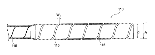
end
CA 02878821 2015-01-09
portion 17 and the shaft proximal end portion 16 constituted of different
materials can be joined firmly.
[0105] 100 electrode catheter
10 catheter shaft
5 11 shaft proximal end portion
110 metal tube
115 slit
12 shaft distal end portion
120 resin tube
10 121 first multi-lumen tube
122 second multi-lumen tube
1231, 1241 first lumen
1232, 1242 second lumen
1233, 1243 third lumen
15 1234, 1244 fourth lumen
125, 126 constituent resin of multi-lumen tube
13 resin covering layer
130 heat-shrinkable resin tube
20 operating handle
20 21 handle main body
22 knob
23 rotation plate
31 tip electrode
32 to 34 ring-shaped electrode
25 41 to 44 lead wire
23 rotation plate
CA 02878821 2015-01-09
36
50 pull wire
70 connector
150 electrode catheter
15 catheter shaft
16 shaft proximal end portion
165 slit
17 shaft distal end portion
171 first multi-lumen tube 171
172 second multi-lumen tube 172
1731 first lumen
1732 second lumen 1732
1733 third lumen 1733
1734 fourth lumen 1734
175 constituent resin of multi-lumen tube
18 resin covering layer
operating handle
to 38 ring-shaped electrode
to 48 lead wire
core wire