Note: Descriptions are shown in the official language in which they were submitted.
CA 02879183 2015-01-13
WO 2014/043106
PCT/US2013/058999
CARTRIDGES , SYSTEMS AND l'AXTRODS FOR PREPARATION OF BEVERAGES
Fieid
[0001j The present application relates to cartridges, systems
and methods for preparation of beverages.
Background
[0002] Cartridges for use in the preparation of beverages are
well known. For example, it is known to provide a cartridge for
use in a beverage preparation machine which, in use, is pierced
by a piercing element of the beverage preparation machine to
allow hot water to flow through the cartridge to brew a beverage
medium such as roasted ground coffee.
[0003] US2010/0303964 describes one such cartridge including
a container, a beverage medium, a filter and a filter guard. The
filter guard is arranged to be contacted by a piercing member
and thereby be displaced upwardly during use. Displacement of
the filter guard during use causes distortion of the filter and
the beverage medium that may lead to inconsistent brewing of the
beverage medium. Disruption to the beverage medium can lead to
the formation of crevices in the beverage medium during brewing
which allows the hot water to preferentially flow through the
crevices rather than a uniform bed of the beverage medium. In
addition, the need for the piercing element of the beverage
preparation machine to displace the filter guard increases the
force required to close a brew chamber of the beverage
preparation machine and may also lead over time to blunting of
the piercing element.
Summary
[0004] The present disclosure provides a cartridge for
preparation of a beverage comprising:
- -
CA 02879183 2015-01-13
WO 2014/043106
PCT/US2013/058999
a closed container defining a container volume;
a filter located in the closed container to divide the
container volume into an ingredient chamber volume and a
filtrate volume;
a beverage medium located in the ingredient chamber volume;
and
a guard element located in the filtrate volume;
wherein the guard element is separately-formed from the
closed container and located within the filtrate volume to
define an outlet zone, the guard element being interposed
between the filter and the outlet zone;
wherein the guard element is configured to prevent
encroachment of the filter into the outlet zone such that in use
on full extension of a piercing element of a beverage
preparation apparatus the piercing element is enabled to be
placed in fluid communication with the outlet zone without the
piercing element contacting the guard element or filter.
[0005] in one embodiment the guard element may be configured
to provide physical support to at least a portion of the filter
in use.
[0006] In one embodiment, the guard element acts as a filter
guard to help prevent the filter being damaged during the
piercing of the cartridge. in addition, the physical support of
the filter coupled with the non-contact of the piercing element
with the guard element or filter helps to prevent disturbance of
the beverage medium during brewing or blunting of the piercer
element.
[0007] The guard element may be configured to provide a
clearance distance between the piercing surface and the filter,
which is greater than a penetration distance of said piercing
element into the closed container.
-2 -
CA 02879183 2015-01-13
WO 2014/043106
PCT/US2013/058999
[0008] The guard element may comprise a filter support
surface and at least one strut portion for spacing the filter
support surface from the piercing surface of the cartridge.
[0009] In one aspect the strut portion may comprise a
circumferential side wall. The circumferential side wall may
comprise a plurality of elongate support ribs interposed by
elongate filtrate apertures. In one aspect the circumferential
side wall may be inwardly-tapered such that a diameter of the
filter support surface is less than a diameter of a distal end
of the circumferential side wall. In this aspect the guard
element and/or outlet zone may be frustoconical in shape.
[0010] The filter support surface may comprise a plurality of
elongate support riba interposed by elongate filtrate apertures.
[0011] In one aspect the closed container may comprise a cup-
shaped body and a lid, the cup-shaped body comprising a base
defining the piercing surface and a side wall extending from the
base to the lid, wherein the guard element comprises a filter
support surface and at least one strut portion for spacing the
filter support surface from the piercing surface of the
cartridge, wherein a distal end of said strut portion is abutted
into an angle formed between the side wall and the base. In this
manner the guard element may be reliably located relative to the
rest of the closed container. The guard element may also assist
in increasing the structural strength of the cartridge as the
guard element may form a load-bearing member, in particular for
radial loads.
[0012] The side wall in the region of the base may be
inwardly-tapered so as to retain the distal end of the strut
portion. Use of an inward-taper is efficient in that no separate
fixture is required to locate the guard element and the guard
element may be easily assembled with the cup-shaped body in an
automated process.
-3-.
CA 02879183 2015-01-13
WO 2014/043106
PCT/US2013/058999
[0013] In another aspect the guard element may be configured
to define an annular outlet zone. The guard element may comprise
inner and outer circumferential side walls depending from a
filter support surface of the guard element. The inner and/or
outer circumferential side wall may comprise a plurality of wall
sections interposed by filtrate apertures. The guard element may
comprise a lower flange element defining a lower rim of the
guard element. As in the above aspects the guard element may be
insertable into a capsule having a cup-shaped body and a lid,
wherein a the lower rim of the lower flange element is abutted
into an angle formed between the side wall and the base. In this
manner the guard element may be reliably located relative to the
rest of the closed container. The guard element may also assist
in increasing the structural strength of the cartridge as the
guard element may form a load-bearing member, in particular for
radial loads.
[0014] The side wall in the region of the base may be
inwardly-tapered so as to retain the lower flange element. Use
of an inward-taper is efficient in that no separate fixture is
required to locate the guard element and the guard element may
be easily assembled with the cup-shaped body in an automated
process.
[00151 The side wall of the cartridge may be provided with a
plurality of flutes defining a plurality of channels for
directing filtrate downwardly towards the base of the cartridge.
[0016] The guard element may be rigid.
[0017] The guard element may be a one-piece moulding.
[0018] The cup-shaped body and/or guard element may be formed
from polypropylene, polyester, polystyrene, nylon, polyurethane,
acetal, acetal grade polyoxylene methylene copolymer (e.g.
Centrodal C), other engineering plastics, composites, ceramics,
or biodegradable plastics such as degradable polyethylene (for
- 4 -
CA 02879183 2015-01-13
WO 2014/043106
PCT/US2013/058999
example, SPITEK supplied by Symphony Environmental, Borehamwood,
United Kingdom), biodegradable polyester amide (for example, BAK
1095 supplied by Symphony Environmental), or poly lactic acids
(PLA) (supplied by Cargill, Minnesota, USA). The cup-shaped body
and/or guard element may comprise a laminate of materials. The
laminate may comprise a layer providing a barrier to moisture
and or gas transmission. An example is EVOH. The laminate may
comprise one or more adhesive layers.
[0019] The guard element may be a stackable component. It may
be provided with a feature to enable easy separation of
individual guard elements from a stack of guard elements. In one
aspect the feature comprises a spacing proiection that defines a
minimum clearance between stacked guard elements. The spacing
projection may be located on or near a central axis of the guard
element.
[0020] The filter may comprise a side wall and a base. The
filter may be cup-shaped. The filter may be formed from one
piece or one moulding. Suitable materials for the filter include
woven and non-woven materials, paper, and cellulose as well as
plastics such as polypropylene and polyethylene. The paper or
cellulose material may contain fibres of another material, for
example, polypropylene or polyethylene.
[0021] The lid may be formed from polyethylene,
polypropylene, polyesters including polyethylene terephthalate,
polyvinyl chloride, polyvinylidene chloride, polyamides
including nylon, polyurethane, paper, viscose and/or a metal
foil. The lid may comprise a laminate, be metallised or formed.
of copolymers. In one example, the iid comprises a
polypropylene-aluminium laminate.
[0022] The disclosure finds particular application where the
beverage medium is an extractable/infusible product such as
roasted ground coffee or leaf tea. However, the beverage medium
- 5 -
02879183 2015-01-13
WO 2014/043106
PCT/US2013/058999
may alternatively be a water-soluble ingredient such as instant
spray-dried or freeze-dried coffee, a chocolate powder, a milk
powder or a creamer powder. Milk powders may include dried
skimmed milk, part-skimmed milk, and whole milk, dried milk
protein concentrates, isolates, and tractions, or any
combination thereof. Creamer powders may be manufactured from
dairy and/or non-dairy food ingredients and typically contain
emulsified fat, stabilized by protein or modified starch,
dispersed in a carrier that facilitates drying, especially spray
drying. The powdered product may be agglomerated. As a further
alternative the beverage medium may be a mixture of
extractable/infusible ingredients and water-soluble ingredients,
for example a mixture of roasted ground coffee and instant
freeze-dried coffee.
[0023] in one aspect the closed container may comprise a cup-
shaped body and a lid, the cup-shaped body comprising a base
defining the piercing surface and a container side wall
extending from the base to the lid, wherein the filter comprises
an upper rim that is connected at or near a lid-end of the
container side wall and/or between the container side wall and
the lid. and further comprises a filter side wall that is
unconnected to the container side wall. The filter may comprise
a base portion and the guard element may provide physical
support to substantially the whole base portion of the filter.
[0024] in a particular aspect there is provided a cartridge
for preparation of a beverage comprising:
a closed container comprising a cup-shaped body and a lid,
the cup-shaped body comprising a base defining a piercing
surface and a container side wall extending from the base to the
lid, the closed container defining a container volume;
- 6 -
CA 02879183 2015-01-13
WO 2014/043106
PCT/US2013/058999
a filter located in the closed container to divide the
container volume into an ingredient chamber volume and a
filtrate volume;
a beverage medium located in the ingredient chamber volume;
and
a guard element located in the filtrate volume comprising a
filter support surface and a circumferential side wall for
spacing the filter support surface from the piercing surface of
the cartridge;
wherein a distal end of said circumferential side wall is
abutted into an angle formed between the container side wall and
the base;
wherein the guard element is separately-formed from the
closed container and located within the filtrate volume to
define an outlet zone, the guard element being interposed
between the filter and the outlet zone;
wherein the guard element is configured to provide physical
support to at least a portion of the filter in use and to
prevent encroachment of the filter into the outlet zone such
that on piercing of the piercing surface by a piercing element
of a beverage preparation apparatus the piercing element is
enabled to be placed in fluid communication with the outlet zone
without the piercing element contacting the guard element or
filter.
[0025] The present disclosure also provides a beverage
preparation system comprising a beverage preparation apparatus
and a cartridge as described in any of the aspects noted above,
the beverage preparation apparatus comprising an outlet piercing
element adapted to pierce a piercing surface of said cartridge
to enable fluid communication between the outlet zone of said.
cartridge and an outlet of said beverage preparation apparatus
- 7 -
CA 02879183 2015-01-13
WO 2014/043106
PCT/US2013/058999
without the piercing element contacting the guard element or
filter of said cartridge.
[0026] The beverage preparation apparatus may be configured
such that the outlet piercing element is off-set from a central
axis of the piercing surface. This may be advantageous where the
guard element comprises a centrally located spacing projection
so as to avoid contact between the spacing projection and the
outlet piercing element. Likewise, this may be advantageous
where the outlet zone is annularly configured.
[0027] The present disclosure further provides a method for
preparing a beverage comprising:
providing a closed container containing a beverage medium
located in a ingredient chamber volume; said ingredient chamber
volume being separated from a filtrate volume by a filter; said
filtrate volume containing a separately-formed guard element;
piercing an inlet in an inlet piercing surface of the
container using an inlet piercing element;
piercing an outlet in an outlet piercing surface of the
container using an outlet piercing element;
supplying fluid through the inlet into the ingredient
chamber volume to form a beverage from the beverage medium;
passing the beverage through the filter into the filtrate
volume;
supporting the filter using the guard element to prevent
encroachment of the filter into an outlet zone located between
the guard element and the outlet piercing surface; and
discharging the beverage from the filtrate volume via the
outlet zone and outlet.
- 8 -
CA 02879183 2015-01-13
WO 2014/043106
PCT/US2013/058999
Brief Description of the Drawings
[0028] Aspects of the present disclosure will now be
described, by way of example only, with reference to the
accompanying drawings, in which:
[0029] Figure 1 is a cross-sectional elevation of a cartridge
according to one embodiment of the present disclosure;
[0030] Figure 2 is a perspective cross-sectional view of the
cartridge of Figure 1;
[0031] Figure 3 is a perspective view of a filter guard of
the cartridge of Figure 1;
(0032] Figure 4 is a cross-sectional elevation of the
cartridge of Figure 1 during dispensation;
(0033] Figure 5 a perspective view of another embodiment of a
filter guard of the present disclosure; and
[0034] Figure 6 is a cross-sectional elevation of a cartridge
containing the filter guard of Figure 5 during dispensation.
Detailed Description
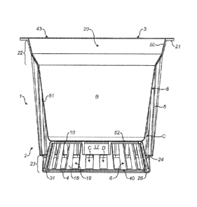
[0035] As shown in Figure 1, in a first aspect the cartridge
1 comprises a cup-shaped body 2, a lid 3, a filter guard 6 and a
filter 8.
[0036] The cup-shaped body 2 of Figure 1 comprises a circular
base 4 and an upwardly extending sidewall 5 that terminates at
an upper rim 21 which defines an open upper end 20 of the cup-
shaped body 2. As shown in Figure 2, the side wall 5 is provided
on its inner face with a plurality of flutes 28 that project
radially inwards so as to define channels 29 interposed between
the flutes 28 which run down a substantial length of the side
. wall 5 from the open upper end 20 towards the base 4. The side
wall 5 is generally frustoconical in shape with a diameter at
the open upper end 20 being larger than a diameter at the side
wall 5 adjacent to the base 4. An upper region of the side wall
- 9 -
CA 02879183 2015-01-13
WO 2014/043106
PCT/US2013/058999
adjacent to the upper rim 21 has an inwardly tapering section
22 extending downwardly from the upper rim 21. In addition, the
side wall 5 in the region of the base 4 is provided with an
outwardly tapering section 23. An upper end of the outwardly
tapering region 23 connects to the remainder of the side wall 5
at an= out-turned shoulder 24.
[0037] The
base 4, illustrated for example in Figure 4, is
generally flat and includes an annular recess 26 which. is
provided at its outer periphery at an angle 27 between the base
4 and the side wall 5. A flat portion 4a of the base 4 provides
a lower piercing surface 40 of the cartridge 1.
[0038] A
plurality of cup-shaped bodies 2 may be stacked
together prior to assembly of the cartridges 1.
[0039] The
lid 3 comprises a disc that is bonded or otherwise
sealed to the upper rim 21 of the cup-shaped body 2 to close the
open upper end 20 of the cartridge 1. The lid 3 defines an
upper piercing surface 43 of the cartridge 1.
[0040] In one
embodiment, the filter 8 has a generally cup-
shaped form having an upper filter rim 50 which is bonded or
otherwise sealed to the cup-shaped body 2 either at or near the
upper rim 21. In a non-illustrated example the filter rim 50 is
bonded between the upper rim 21 of the cup-shaped body 2 and the
lid. 3. A
filter side wall 51 may extend downwardly from the
filter rim 50 and may be closed off at a lower end by a filter
base 52 as illustrated. The filter 8 may be formed from a single
piece or moulding of filter material.
[0041] The
filter guard 6 may be formed as a separate
component from the cup-shaped body 2 and filter 8 and may be
located at a lower end of the cuo-shaped body 2 as shown in
Figures 1 and 2. As most clearly shown in the embodiment of
Figure 3, the filter guard 6 comprises an upper portion 9
defining an upper surface 10 and a circumferential wall 11
- 10 -
CA 02879183 2015-01-13
WO 2014/043106
PCT/US2013/058999
which, in the illustrated embodiment, extends downwardly and
outwardly from the upper portion 9 to terminate at a lower rim
31. The upper portion 9 comprises an outer circumferential rim
14 and an inner circumferential rim 15 which are joined together
by a plurality of radial bars 12 which define interposed upper
apertures 13. The inner rim 15 defines a central aperture 16
which extends downwardly through a downwardly extending tube 17.
The circumferential wall 11 may include a plurality of axially-
orientated (or substantially axially-orientated) bars 18 which
extend from the lower rim 31 to the outer rim 14 and which
define interposed side apertures 19. The filter guard 6,
illustrated in Figure 3, is generally frustoconical in shape
with a diameter of the lower rim 31 being greater than the
diameter of the outer rim 14.
[0042] The filter guard 6 may be rigid; meaning that it has
sufficient structural strength so as not to undergo any
substantial deformation during the use described below.
[0043] Advantageously, the filter guard 6 is shaped so as to
be a stackable component prior to assembly of the cartridge L.
The downwardly extending tube 17 serves to ensure that adjacent
filter guards 6 are spaced slightly from one another when
stacked to ensure ease of separation of each filter guard 6 from
the stack.
[0044] As most clearly shown in Figure 2, the lower rim 31 of
the filter guard 6 may be located in the annular recess 26 of
the cup-shaped body 2 with the lower rim 31 held in contact with
the angle 27 between the side wall 5 and the base 4.
[0045] In an exemplary assembly technique for the cartridge 1
as shown in Figure 1, the filter guard 6 is first inserted into
the open topped cup-shaped body 2 and pushed downwardly so as to
engage the lower rim 31 as a push fit into contact with the
angle 27 and recess 26. Insertion of the filter guard 6 in one
- 11 -
CA 02879183 2015-01-13
WO 2014/043106 PCT/US2013/058999
embodiment, is accommodated by flexure of the side wall 5 to =
allow the relatively rigid lower rim 31 to pass the smaller
diameter of the cup-shaped body 2 at the level of the out-turned.
shoulder 24. The side wall 5 is resilient in nature such that
once inserted past the out-turned. shoulder 24 the filter guard 6
is gripped and retained by the side wall 5 in contact with the
angle 27 between the base 4 and the side wall 5 without the
requirement for any additional bonding or connection means.
[0046] Next, the filter 8 is inserted into the cup-shaped
body 2 through the open upper end 20 and bonded or otherwise
connected to or near the upper rim 21, for example by heat
sealing.
[0047] As shown in Figure 1, with the filter 8 in place a
container volume of the cartridge 1 is divided into a beverage
ingredient volume S to one side of the filter 8 and a filtrate
volume C to the other side of the filter 8. The filter guard 6
is local:ad in the filtrate volume C beneath the filter 8. The
channels 29 formed between the flutes 28 form part of the
filtrate volume C as they are 'downstream' of the filter 8.
[0048] A portion of beverage ingredients 7, such as roasted
ground coffee, is filled through the open upper end 20 into the
beverage ingredient volume B. The cartridge 1 is then closed by
sealing the lid 3 to the upper rim 21 with or without
sandwiching of the filter rim 50 therebetween. Two or more of
the assembly steps described above may be combined into a single
assembly process step.
[0049] In Figure 1, when assembled the filter base 52 is
physically supported by the upper surface 10 of the filter guard
6. In one embodiment, the upper surface 10 of the filter guard 6
is configured to ensure that the material of the filter 8 does
not extend into a portion of the filtrate volume C which can be
considered an outlet zone D of the cartridge 1. The outlet zone
- 12 -
CA 02879183 2015-01-13
WO 2014/043106
PCT/US2013/058999
D is defined as the volume between the filter guard 6 and the
base 4 of the cup-shaped body 2. In one embodiment, filter guard
6 is configured to receive the piercing element such that, when
the piercing element is fully extended in use, the piercing
element does not move filter guard 6. In one embodiment, filter
guard 6 is configured to receive the piercing element such that,
when the piercing element is fully extended in use, the piercing
element does not contact filter guard 6. In one embodiment,
filter guard 6 defines an aperture 56a that may be configured to
receive a piercing element of a beverage preparation apparatus,
such that, when the piercing element is fully extended into
outlet zone D in use the piercing element is placed in fluid
communication with the outlet zone D.
[0050] In
use, as shown in Figure 4, the cartridge 1 is
inserted into a beverage preparation apparatus cf known type in
which an inlet piercing element 55 and outlet piercing element
56 are engaged with the cartridge 1 to permit brewing and
dispensation. As shown, the inlet piercing element 55 pierces
the upper piercing surface 43 of the cartridge 1 to form an
inlet so as to provide fluid communication to the beverage
ingredient volume B. The outlet piercing element 56 pierces the
lower piercing surface 40 of the base 4 to form an outlet to
provide an exit flow path for beverage formed from the beverage
ingredient 7 to leave the cartridge 1 and thereafter the
beverage preparation apparatus can be dispensed to a receptacle
such as a cup. The
outlet piercing element 56 may be offset
from the centre of the cartridge 1 so as not to be impeded by
the downwardly-extending tube 17.
[0051]
Aqueous medium, such as hot water, is injected into
the cartridge 1 through the inlet piercing element 55 to contact
the beverage medium 7. A beverage extract is thus formed which
passes through the filter 8 into the filtrate volume C. The
- 13 -
CA 02879183 2015-01-13
WO 2014/043106
PCT/US2013/058999
beverage extract passes through the filter side wall 51 into the
channels 29 where it is able to run downwardly and into the
outlet zone D via the side apertures 13 in the filter guard 6.
Extract also passes through the filter 8 through the filter base
52 and into the outlet zone D through the upper apertures 13 and
central aperture 16 of the filter guard 6.
[0052]
Advantageously, as shown in Figure 4, a distance d
between the base 4 of the cup-shaped body 2 and the lower face
of the radial bars 12 of the filter guard 6 is greater than a
penetration distance p of the outlet piercing element 56 into
the cartridge 1. This
ensures that during use the outlet
piercing element 56 does not contact either the filter guard 6
or the filter 8. In one embodiment, aperture 56a of filter guard
6 extends from base 4 toward upper surface 10 a distance that is
greater than penetration distance p.
[0053]
Figure 5 shows another aspect of filter guard 6' that
may be incorporated into the capsule 1 in place of the filter
guard 6 of Figure 3. In describing this aspect, features common
to the previous aspect, in particular the configuration of the
cup-shaped body 2, lid 3 and filter 8 will not be described
further and reference should be made to the passages above.
[0054] As
before, the filter guard 6' may be formed as a
separate component from cup-shaped body 2 and is located at a
lower end of the cup-shaped body 2 as shown in Figure 6. The
filter guard 6' comprises an annular portion defining an upper
surface 10', an outer circumferential wall 11' and an inner
circumferential wall, both walls extending downwardly from the
upper portion to adjoin a lower flange element. The lower flange
element defines a lower rim 31'. A
central aperture 16' is
provided within the upper surface 10'. The inner circumferential
wall comprises a plurality of wall sections 18' which define
interposed side apertures 19'.
- 14 -
CA 02879183 2015-01-13
WO 2014/043106
PCT/US2013/058999
[0055] The
filter guard 6' may be rigid meaning that it has
sufficient structural strength so as not to undergo any
substantial deformation during the use described below.
[0056]
Assembly of the cartridge 1 is as described previously
except that the filter guard 6' is inserted such that the lower
rim 31' is engaged in or close to the angle 27 of the cup-shaped
body 2. As above, the inwardly-tapered section 23 serves to
maintain the filter guard 6' in the correct position.
[0057] As can
be seen from Figure 6, when assembled the
filter base 52 is physically supported by the upper surface 10'
of the filter guard 6' which ensures that the material of the
filter 8 does not extend into a portion of the filtrate volume C
which can be considered an outlet zone 0 of the cartridge 1. The
outlet zone D is defined as the enclosed volume between the
filter guard 6' and the base 4 of the cup-shaped body 2.
[0056] Use of
the cartridge 1 is as described above except
that beverage extract passing through the filter 8 is channelled
to the outlet piercer 56 via the side apertures 19' and the
annular outlet zone D.
[0059] In a
modification of the above aspect, the outer
circumferential wall 11' may also be provided with apertures 19'
for passage of beverage flow into the outlet zone D.
[0060] From the foregoing it will be appreciated that
cartridges for preparation of beverages and components for such
cartridges are provided.
- 15 -