Note: Descriptions are shown in the official language in which they were submitted.
CA 02879646 2015-01-21
PCT/CN2013071370
SPECIFICATION
Electronic Cigarette
FIELD OF THE INVENTION
[0001] The present invention relates to technical field of electronic
cigarette and more particularly, relates to an electronic cigarette of which
connection is realized by magnetic force absorption.
BACKGROUD OF THE INVENTION
[0002] With more concerns given to people health, people have been
aware of damages of tobacco to body health and as a result, electronic
cigarette appears. For an electronic cigarette, cigar liquid is atomized by
the
atomizer such that the user can smoke. During formation process of cigar
liquid, hazardous substance such as nicotine and tar is removed from cigar
liquid; damage to user's body health is greatly decreased. Also, as no
hazardous substance such as nicotine and tar is contained in cigar liquid,
using of the electronic cigarette will gradually reduce reliance of user on
traditional cigarette. Therefore, electronic cigarette may also assist in
getting
rid of smoking.
[0003] In general, an electronic cigarette includes an suction stick and
a power supply stick. A cigar liquid cup for storage of cigar liquid and an
atomizer for atomizing cigar into smoke are disposed in the suction stick. A
battery for supplying power to the atomizer is contained in the power supply
stick. For a conventional electronic cigarette, the suction stick and power
supply stick are connected with each other by screwing. This kind of
connection will result in time consumption and inconvenience during
CA 02879646 2015-01-21
PCT/CN2013071370
assembling and disassembling process. In addition, the internal construction
of the suction stick is complex thus leading to inconvenience in maintenance
and replacement of the atomizer. Moreover, using of the screwing
connection will result in misalignment between the electrode of the power
supply stick and that of the suction stick due to bias between the electrodes
during contact of the electrodes. Too tight or too loose screwing will both
easily result in misalignment. After a period of use, the misalignment will
become serious and, bad contact between the electrodes will be caused and
accordingly, the atomizer will not work normally.
[0004] Therefore, there is need for providing an electronic cigarette
which is easy to be assembled and disassembled, has simple construction,
easy to be repaired and replaced, has good electrical contact, and has long
lifetime.
SUMMARY OF THE INVENTION
[0005] The object of the invention is to provide an electronic cigarette
which is easy to be assembled and disassembled and has simple
construction.
[0006] To realize the above object, the following technical solution is
proposed. The invention provides an electronic cigarette including an suction
stick and a power supply stick. The suction stick has a first and second
suction stick electrodes contained therein. The power supply stick has a first
and second power supply stick electrodes contained therein. When the
suction stick and power supply stick are connected with each other, the first
suction stick electrode is electrically connected to the first power supply
2
CA 02879646 2015-01-21
PCT/CN2013071370
stick electrode, while the second suction stick electrode is electrically
connected to the second power supply stick electrode. The suction stick and
power supply stick are connected together by magnetic force absorption. In
the present invention, the suction stick and power supply stick are connected
together by magnetic force absorption and therefore, it has simple
construction, is easy to be assembled and disassembled, and is easy to be
maintained and replaced.
[0007] Furthermore, a magnetic absorption element is disposed in at
least one of the connection end of the suction stick and connection end of the
power supply stick. The connection end of the suction stick is provided with
a metal suction stick connection member, while the connection end of the
power supply stick is provided with a metal power supply stick connection
member. The suction stick connection member and power supply stick
connection member are detachably connected with each other, and they are
engaged with each other by absorption force of the magnetic absorption
element.
[0008] The magnetic absorption element may take various forms and
in some embodiments, it may be permanent magnet. The suction stick
connection member and power supply stick connection member are attracted
together and are pressed against the top end of the permanent magnet.
[0009] Furthermore, the permanent magnet is held in the suction stick
connection end or power supply stick connection end by a metal holding
sleeve. The metal holding sleeve may be made of conductive material such
as iron and copper.
[0010] Moreover, the permanent magnet is disposed on the power
3
CA 02879646 2015-01-21
PCT/CN2013071370
supply stick connection end and a fixation hole is defined in the permanent
magnet. The first power supply stick electrode is received in the fixation
hole of the permanent magnet. An insulation member is disposed between
the permanent magnet and the first power supply stick electrode. The power
supply stick connection member is the second power supply stick electrode,
and the suction stick connection member is the second suction stick
electrode. The first suction stick electrode is placed in the suction stick
connection member. An insulation member is disposed between the first and
second suction stick electrodes.
[0011] Moreover, the holding sleeve is of a circular cup and includes a
side wall, a bottom wall and a cavity defined by the side wall and bottom
wall together. The holding sleeve is pressed against and secured on an inner
wall of the power supply stick connection end by its side wall. A locating
step is formed on inner side of the inner wall of the holding sleeve for
supporting the permanent magnet. The permanent magnet is installed in the
cavity of the holding sleeve and the bottom of the permanent magnet is
supported on the locating step. One end of the power supply stick connection
member and one end of the suction stick connection member are inserted
into the holding sleeve and pressed against the top end of the permanent
magnet such that the permanent magnet is held in place. A through hole is
defined in the bottom wall of the holding sleeve through which the first
power supply stick electrode passes.
[0012] Preferably, the power supply stick connection member is
pressed against and secured on the power supply stick connection end by the
holding sleeve and, the holding sleeve is pressed against and secured on the
4
CA 02879646 2015-01-21
PCT/CN2013071370
inner wall of the power supply stick connection end. The permanent magnet
is held in the holding sleeve.
[0013] Furthermore, the power supply stick connection member
includes a first connection portion of cylinder in which a first cavity is
formed for insertion with the suction stick connection member. A locating
step, which is radially outwardly extended from an outer wall of the first
connection portion and used for engaging with the power supply stick
connection end, is provided on the outer wall of the first connection portion.
The power supply stick connection member is pressed against and secured
on the inner wall of the power supply stick connection end by the outer wall
of the first connection portion. Using the above structure, the power supply
stick connection member is simply coupled with the suction stick connection
member.
[0014] In some embodiments, the power supply stick connection
member further includes a second connection portion for insertion with the
suction stick connection end. The second connection portion extends axially
upon the locating step away from the first connection portion such that a
cylinder is formed. The first and second connection portions communicate
with each other. A second cavity is defined in the second connection portion
for containing the suction stick connection end. The inner wall of the second
connection portion is interference-fitted with the outer wall of the suction
stick connection end. This structure enhances connection reliability between
the suction stick and power supply stick, makes connection easy and,
produces good electrical contact between the electrodes of the suction stick
and power supply stick.
CA 02879646 2015-01-21
PCT/CN2013071370
[0015] Preferably, the suction stick connection member includes an
upper portion and a lower portion both of which are of a cylindrical shape.
The upper portion is intended for connection with the suction stick
connection end, whereas the lower portion is intended for connection with
the power supply stick connection member. A locating step, which is
extended outwardly and is pressed against the suction stick connection end,
is formed between the upper and power portions. The locating step also
functions to be pressed against the power supply stick connection member so
as to realize location limiting purpose. A locking ring for mounting the first
suction stick electrode is formed on the inner wall of the lower portion. The
first suction stick electrode is secured in the locking ring by an insulation
member. A venting hole is defined in the middle portion of the first suction
stick electrode. The outer wall of the upper portion of the suction stick
connection member is pressed against and inserted into the inner wall of the
suction stick connection end. The power portion of the suction stick
connection member is inserted into the power supply stick connection
member for engaging the same. This construction makes the suction stick
connection end and power supply stick connection end be connected more
tightly.
[0016] Preferably, the first power supply stick electrode is of a
cylindrical shape. A circular locating step is formed on the middle
circumferential surface of the first power supply stick electrode and said
locating step divides the first power supply stick electrode into an upper
portion and a lower portion. In addition, an axially extended venting hole is
defined in the first power supply stick electrode.
6
CA 02879646 2015-01-21
PCT/CN2013071370
[0017] Preferably, the insulation member is sleeved on the first power
supply stick electrode and, the first power supply stick electrode and
insulation member are inserted into the fixation hole of the permanent
magnet and are locked therein. The bottom portion of the insulation member
is pressed against the top portion of the locating step such that the locating
step of the first power supply stick electrode is located below the bottom
portion of the permanent magnet and is isolated from the permanent magnet.
[0018] Moreover, an insulation washer is disposed between the first
power supply stick electrode and holding sleeve. An axially extended
venting hole is defined in the middle portion of the insulation washer. The
lower portion of the first power supply stick electrode passes through the
venting hole of the insulation washer and through hole of the holding sleeve
and then extends out of the bottom wall of the holding sleeve. The insulation
washer isolates the first power supply stick electrode from the holding
sleeve.
[0019] Further, a resilient member is sleeved on the lower portion of
the first power supply stick electrode. The two ends of the resilient member
are respectively pressed against the locating step of the first power supply
stick electrode and insulation washer. The first power supply stick electrode,
permanent magnet, power supply stick connection member and holding
sleeve are engaged each other tightly due to pre-tension generated by
compression of the resilient member. In addition, the resilient member
makes the permanent magnet be pressed more tightly against both of the
power supply stick connection member and suction stick connection member,
thus leading to more stable connection structure, tighter physical and
7
CA 02879646 2015-01-21
PCT/CN2013071370
electrical contact between the first power supply stick electrode and the
first
suction stick electrode. Generally, the resilient member is a spring.
[0020] As an alternative embodiment, the permanent magnet may also
be disposed at the suction stick connection end. The fixation hole of the
permanent magnet receives the first suction stick electrode. An insulation
member is provided between the permanent magnet and first suction stick
electrode. The suction stick connection member is the second suction stick
electrode, while the power supply stick connection member is the second
power supply stick electrode. The first power supply stick electrode is
disposed at the middle portion of the power supply stick connection member.
An insulation member is disposed between the first and second power
supply stick electrodes. The substantial features of this embodiment are
consistent with those of the above-mentioned embodiment and therefore, no
further description will be provided hereinafter.
[0021] As an alternative embodiment, in addition to the permanent
magnet, the magnetic absorption element may also be made of
electromagnetic coil assembly. The suction stick connection member and
power supply stick connection member are attracted together and are pressed
against the top end of the electromagnetic coil assembly.
[0022] Furthermore, the electromagnetic coil assembly is secured in
the suction stick connection end or power supply stick connection end by a
base.
[0023] In some embodiments, the electromagnetic coil assembly is
placed inside the power supply stick connection end and the electromagnetic
coil assembly includes a magnetic core and a coil enwound on the magnetic
8
CA 02879646 2015-01-21
PCT/CN2013071370
core. A through hole is defined in the magnetic core. A groove is defined in
the outer wall of the magnetic core for enwinding the coil thereon. A radially
extended locating step is defined in the upper end of the magnetic core. The
first power supply stick electrode is inserted into the through hole of the
magnetic core. An insulation sleeve is located between the magnetic core
and first power supply stick electrode. The power supply stick connection
member is used as the second power supply stick electrode.
[0024] Further, the insulation sleeve is of a cylindrical shape. A
circular locating step is formed on the middle circumferential surface of the
insulation sleeve and said locating step divides the insulation sleeve into an
upper portion and a lower portion. In addition, an axially extended venting
hole is defined in the insulation sleeve. A receiving chamber is defined in
the
lower portion of the insulation sleeve for communicating with the through
hole. The first power supply stick electrode is inserted into the through hole
of the insulation sleeve. The locating step of the insulation sleeve is
located
between the electromagnetic coil assemble and base and isolates them from
each other.
[0025] Preferably, the first power supply stick electrode is of a
cylindrical shape. A circular locating step is formed on the middle
circumferential surface of the first power supply stick electrode and said
locating step divides the first power supply stick electrode into an upper
portion and a lower portion. In addition, an axially extended venting hole is
defined in the first power supply stick electrode. The insulation sleeve is
sleeved on the first power supply stick electrode and, the first power supply
stick electrode and insulation sleeve are inserted into the through hole of
the
9
CA 02879646 2015-01-21
PCT/CN2013071370
electromagnetic coil assembly and are locked therein. The lower portion of
the first power supply stick electrode is received into the receiving chamber
of the lower portion of the insulation sleeve. The locating step of the first
power supply stick electrode is pressed against the bottom end of the upper
portion of the insulation sleeve.
[0026] Preferably, the base is of a circular cup and includes a side wall,
a bottom wall and a cavity defined by the side wall and bottom wall together.
The base is pressed against and secured on an inner wall of the power supply
stick connection end by its outer wall. A locating step is inwardly formed on
the upper end of the side wall of the base. A through hole is defined in the
bottom wall of the base through which the first power supply stick electrode
passes.
[0027] Preferably, an axially extended semi-circular stopping wall is
formed on the bottom wall of the base around the through hole. The stopping
wall separates an electric wire for connecting with the first power supply
stick electrode from another electric wire for connecting with the power
supply stick connection member.
[0028] Furthermore, a resilient member is sleeved on the lower
portion of the first power supply stick electrode. The two ends of the
resilient member are respectively pressed against the locating step of the
first
power supply stick electrode and inner side of the bottom wall of the base.
The first power supply stick electrode, permanent magnet, power supply
stick connection member and base are engaged each other tightly due to
pre-tension generated by compression of the resilient member. In addition,
the resilient member makes the electromagnetic coil assembly be pressed
CA 02879646 2015-01-21
PCT/CN2013071370
more tightly against both of the power supply stick connection member and
suction stick connection member, thus leading to more stable connection
structure, tighter physical and electrical contact between the first power
supply stick electrode and the first suction stick electrode. Generally, the
resilient member is a spring.
[0029] Moreover, the power supply stick connection member is of a
cylindrical shape and, a locating step extended radially outwardly is formed
on the upper end thereof for engaging the power supply stick connection end.
The side wall of the power supply stick connection member is divided into
an upper portion for receiving the suction stick connection member and a
lower portion for receiving the electromagnetic coil assembly, the first
power supply stick electrode and base. The transition location between the
upper portion and lower portion of the side wall of the power supply stick
connection member is provided with a step against which the upper end
surface of the magnetic core of the electromagnetic coil assembly is pressed.
[0030] Preferably, the outer diameter of the upper portion of the side
wall of the power supply stick connection member becomes gradually
greater such that the power supply stick connection member is secured into
the inner wall of the power supply stick connection end. The lower end of
the power supply stick connection member is provided with two wiring pins
for wiring.
[0031] Preferably, the suction stick connection member includes an
upper portion and a lower portion both of which are of a cylindrical shape.
The upper portion is intended for connection with the suction stick
connection end, whereas the lower portion is intended for connection with
11
CA 02879646 2015-01-21
PCT/CN2013071370
the power supply stick connection member. A locating step, which is
extended radially outwardly and is pressed against the suction stick
connection end, is formed between the upper and power portions. The
locating step also functions to be pressed against the power supply stick
connection member so as to realize location limiting purpose. A locking ring
for mounting the first suction stick electrode is formed on the inner wall of
the lower portion. The first suction stick electrode is secured in the locking
ring by an insulation member. A venting hole is defined in the middle portion
of the first suction stick electrode.
[0032] Furthermore, the insulation ring is disposed between the first
suction stick electrode and locking ring of the suction stick connection
member. One end of the insulation ring is provided with inverted rim to be
located at one side of the locking ring, while the other end thereof is
provided with radially extended cylindrical boss to be located at the other
side of the locking ring, hereby the insulation ring being just locked in the
locking ring of the suction stick connection member.
[0033] As an alternative embodiment, the electromagnetic coil
assembly may also be placed inside the suction stick connection end and the
electromagnetic coil assembly includes a magnetic core and a coil enwound
on the magnetic core. A through hole is defined in the magnetic core. A
groove is defined in the outer wall of the magnetic core for enwinding the
coil thereon. A radially extended locating step is defined in the upper end of
the magnetic core. The first suction stick electrode is inserted into the
through hole of the magnetic core. An insulation sleeve is located between
the magnetic core and first suction stick electrode. The suction stick
12
CA 02879646 2015-01-21
PCT/CN2013071370
connection member is used as the second suction stick electrode. The
substantial features of this embodiment are consistent with those of the
above-mentioned embodiment and therefore, no further description will be
provided hereinafter.
[0034] Compared with prior art, the invention has the following
advantages: the power supply stick and suction stick of the electronic
cigarette of the present invention are connected with each other by means of
magnetic force absorption, thus leading to easy assembling and
disassembling, simple construction, easy repair and replacement, good
electrical contact, and long lifetime.
BRIEF DESCRIPTION OF THE DRAWINGS
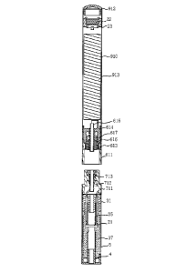
[0035] Figure 1 shows a front view of an electronic cigarette according
to a first embodiment of the invention;
[0036] Figure 2 shows a cross-sectional view of an electronic cigarette
according to a first embodiment of the invention;
[0037] Figure 3 shows an exploded view of an suction stick of an
electronic cigarette according to a first embodiment of the invention;
[0038] Figure 4 shows an exploded view of an suction stick of an
electronic cigarette according to a first embodiment of the invention;
[0039] Figure 5 shows a cross-sectional view of a power supply stick of
an electronic cigarette according to a first embodiment of the invention;
[0040] Figure 6 shows an exploded view of a power supply stick of an
electronic cigarette according to a first embodiment of the invention;
[0041] Figure 7 shows a cross-sectional view of a nozzle case of an
13
CA 02879646 2015-01-21
PCT/CN2013071370
electronic cigarette according to a first embodiment of the invention;
[0042] Figure 8 shows a cross-sectional view of a cigar liquid cup base
of an electronic cigarette according to a first embodiment of the invention;
[0043] Figure 9 shows a cross-sectional view of an suction stick
connection member of an electronic cigarette according to a first
embodiment of the invention;
[0044] Figure 10 shows a cross-sectional view of a power supply stick
connection member of an electronic cigarette according to a first
embodiment of the invention;
[0045] Figure 11 shows a cross-sectional view of a holding sleeve of an
electronic cigarette according to a first embodiment of the invention;
[0046] Figure 12 shows a cross-sectional view of an suction stick
connection member of an electronic cigarette according to a second
embodiment of the invention;
[0047] Figure 13 shows a cross-sectional view of a power supply stick
connection member of an electronic cigarette according to a second
embodiment of the invention;
[0048] Figure 14 shows a cross-sectional view of an electronic cigarette
according to a third embodiment of the invention;
[0049] Figure 15 shows an assembled cross-sectional view of a
magnetic force connection head component of an electronic cigarette
according to a third embodiment of the invention;
[0050] Figure 16 shows a front view of a magnetic force connection
head component of an electronic cigarette according to a third embodiment
of the invention;
14
CA 02879646 2015-01-21
PCT/CN2013071370
[0051] Figure 17 shows a cross-sectional view of a power supply stick
connection member of an electronic cigarette according to a third
embodiment of the invention;
[0052] Figure 18 shows a cross-sectional view of an suction stick
connection member of an electronic cigarette according to a third
embodiment of the invention;
[0053] Figure 19 shows a cross-sectional view of a base of an
electronic cigarette according to a third embodiment of the invention;
[0054] Figure 20 shows a cross-sectional view of an insulation sleeve
of an electronic cigarette according to a third embodiment of the invention;
[0055] Figure 21 shows a cross-sectional view of a first power supply
stick electrode of an electronic cigarette according to a third embodiment of
the invention;
[0056] Figure 22 shows a cross-sectional view of an insulation ring of
an electronic cigarette according to a third embodiment of the invention;
[0057] Figure 23 shows a cross-sectional view of an electromagnetic
coil assembly of an electronic cigarette according to a third embodiment of
the invention;
[0058] Figure 24 shows an exploded view of a power supply stick of an
electronic cigarette according to a third embodiment of the invention;
[0059] Figure 25 shows an exploded view of an suction stick of an
electronic cigarette according to a third embodiment of the invention;
[0060] Figure 26 shows a cross-sectional view of an electronic cigarette
according to a fourth embodiment of the invention; and
[0061] Figure 27 illustrates working principle of the electromagnet of
CA 02879646 2015-01-21
PCT/CN2013071370
the invention.
DETAILED DESCRIPTION OF THE INVENTION
[0062] Referring to figures 1-11 showing a schematic view of the
electronic cigarette according to a first embodiment, the electronic cigarette
includes an suction stick 90 and a power supply stick 91 which are
connected with each other by magnetic force. The suction stick has a first
and second suction stick electrodes contained therein, while the power
supply stick has a first and second power supply stick electrodes contained
therein. When the suction stick and power supply stick are connected with
each other, the first suction stick electrode is electrically connected to the
first power supply stick electrode, while the second suction stick electrode
is
electrically connected to the second power supply stick electrode.
[0063] A magnetic absorption element is disposed in at least one of
the connection end of the suction stick 90 and connection end of the power
supply stick 91 engaged with the connection end of the stem 91. In one
embodiment, the magnetic absorption element may be permanent magnet.
The suction stick connection member and power supply stick connection
member are attracted together and are pressed against the top end of the
permanent magnet 8. The connection end of the suction stick90 is provided
with a metal suction stick connection member 5, while the connection end of
the power supply stick 91 is provided with a metal power supply stick
connection member 911. In one embodiment, the suction stick connection
member 5 and power supply stick connection member 911 are made of iron.
The suction stick connection member 5 and power supply stick connection
16
CA 02879646 2015-01-21
PCT/CN2013071370
member 911 are detachably connected with each other, and they are engaged
with each other by absorption force of the magnetic absorption element 8.
[0064] The permanent magnet 8 is held in the power supply stick
connection member 911 by an iron holding sleeve 914. The permanent
magnet 8 is of an annular shape and a fixation hole is defined in its middle
portion. The first power supply stick electrode 915 is received in the
fixation
hole of the permanent magnet 8. A power supply stick insulation member
916 is disposed between the permanent magnet 8 and first power supply
stick electrode 915. The power supply stick connection member 911 is used
as the second power supply stick electrode.
[0065] The suction stick connection member 5 is the second suction
stick electrode. The middle portion of the suction stick connection member 5
is provided with the first suction stick electrode 13. An suction stick
insulation member 14 is disposed between the first suction stick electrode 13
and the second suction stick electrode.
[0066] The power supply stick connection member 911 and suction
stick connection member 5 may each be stand-alone component independent
of power supply stick 91 or suction stick 90. They may also be integral with
the power supply stick 91 or suction stick 90. The holding sleeve 914 may
also be stand-alone component independent of the power supply stick 91, or
may be integral with the power supply stick 91.
[0067] In present embodiment, the suction stick 90 includes an
absorption sleeve 1, an atomization device 2, a cigar liquid cup 3, a nozzle
case 4 and an suction stick connection member 5 for connecting with the
power supply stick 91. The nozzle case 4 and suction stick connection
17
CA 02879646 2015-01-21
PCT/CN2013071370
member 5 are mounted at two ends of the absorption sleeve 1 respectively.
The atomization device 2 and cigar liquid cup 3 are installed in the
absorption sleeve 1.
[0068] The absorption sleeve 1 is of a hollow cylindrical construction
and is made of transparent or semitransparent plastic material or made of
metal enclosure. As shown in figures 2 and 3, the absorption sleeve 1
includes a first end 11 for placemen of the nozzle case 4 and a second end 12
for placement of the suction stick connection member 5. The first suction
stick electrode 13 and suction stick insulation ring 14 are received in the
suction stick connection member 5 located on the second end 12. A venting
hole is defined in the middle portion of the first suction stick electrode 13.
[0069] As shown in figures 2-6, the atomization device 2 includes an
atomizer 21, an atomizer control circuit board 22 and a circuit board holding
base 23 for accommodating and holding the atomizer control circuit board
22. The atomizer 21 is placed in the absorption sleeve 1, while the atomizer
control circuit board 22 and circuit board holding base 23 are placed in the
power supply stick 91. The atomizer control circuit board 22 is provided
with a mini pneumatic switch for control conduction of the electric circuit
such that the atomizer 21 starts to work.
[0070] As shown in figure 3, the atomizer 21 is intended to change
cigar liquid into smoke and it includes an electric heater coil 211 and a
fiber
member 212 for supporting the electric heater coil 211 and absorbing cigar
liquid. The electric heater coil 211 is enwound on the fiber member 212. The
fiber member 212 works like sponge so as to absorb and store cigar liquid,
and may be made of material with good liquid absorption and storage ability
18
CA 02879646 2015-01-21
PCT/CN2013071370
such as glass fiber or cotton thread. The fiber member 212 is contained and
secured in the cigar liquid cup 3. The two ends of the electric heater coil
211
pass through the cigar liquid cup 3 and then are connected with the two
electrodes inside the power supply stick 91.
[0071] As shown in figures 3-4, the cigar liquid cup 3 includes a cup
base 31, a guiding tube 35, a liquid storage component 37, a locating tube 39
and the above-mentioned nozzle case 4. The cup base 31 and nozzle case 4
are disposed opposite to each other, distanced from each other, and are held
in the inner wall of the absorption sleeve. The guiding tube 35 is held
between the cup base 31 and nozzle case 4. The liquid storage component 37
is secured on the periphery of the guiding tube 35 and is disposed between
the cup base 31 and nozzle case 4. The locating tube 39 is sleeved on the
outer wall of the guiding tube 35 and is pressed against the atomizer 21 for
preventing axial movement of the atomizer 21.
[0072] As shown in figure 8, the cup base 31 is of a cylindrical cup
construction and includes an annular side wall 318 and a circular cup bottom
319, a locating post 311 axially extended from the middle portion of the cup
bottom 319. Herein, an annular cavity 317 is defined between the annular
side wall 318 and locating post 311. A cup bottom venting hole 312 is
defined which extends axially through the locating post 311 and cup bottom
319. Two wire guiding holes (not shown) are defined in the cup bottom 319
for passing the electric heater coil 211. An expansion ring 314 is disposed on
the outer side of the side wall 318 for pressing against the absorption sleeve
1. The cup base 31 is pressed against and secured in the inner wall of the
absorption sleeve 1 by its side wall 318 and expansion ring 314.
19
CA 02879646 2015-01-21
PCT/CN2013071370
[0073] The nozzle case 4 may be formed of silica gel, and its shape
and size are consistent with the inner wall of the absorption sleeve 1. As
shown in figure 7, the nozzle case 4 may take on cylindrical cover body, and
includes an annular side wall 48, a top wall 48 and a locating post 41 axially
extended from the middle portion of the top wall 49. An annular cavity 47 is
defined by the locating post 41 and side wall 48. The nozzle case 4 further
includes a nozzle case venting hole 42 axially extending through the locating
post 41 and top wall 49, and a locating step 43 radially outwardly extended
and matched with the first end 11 of the absorption sleeve 1. The outer
diameter of the nozzle case 4 is slightly larger than the inner diameter of
the
absorption sleeve 1. The nozzle case 4 is pressed against and secured on the
inner wall of the absorption sleeve 1 by its side wall 48. When the cigar
liquid inside the cigar liquid cup 3 gives out, cigar liquid may be added into
the cigar liquid cup 3 after the nozzle case 4 is removed. The locating post
41 of the nozzle case 4 is corresponding to the locating post 311 of the cup
base 31, while the annular cavity 47 of the nozzle case 4 is corresponding to
the annular cavity 317 of the cup base 31, for receiving respectively the two
ends of the guiding tube 35 and two ends of the liquid storage component
37.
[0074] As shown in figure 4, the guiding tube 35 is used to support
the liquid storage component 37 and, it is also used to control height of the
cigar liquid cup 3 and support the fiber member 212. In addition, it is also
used as a path for conducting smoke generated by atomization of cigar liquid
by the atomizer 21 out of the absorption sleeve 1. The guiding tube 35 is a
hollow circular tube and is made of plastic or fiber material such as a glass
CA 02879646 2015-01-21
PCT/CN2013071370
fiber tube. The guiding tube 35 includes an upper portion and a lower
portion. The upper portion of the guiding tube 35 is sleeved on the locating
post 41 of the nozzle case 4 and is sealably connected with the
circumference of the locating post 41 of the nozzle case 4. The lower portion
of the guiding tube is sleeved on the locating post 311 of the cup base 31 and
is sealably connected with the circumference thereof. A holding groove
351 is defined in the guiding tube 35 and extends through its tube wall for
supporting and securing the fiber member 212. The fiber member 212
transverses the two ends of the guiding tube 35, passes through the holding
groove 351 and contacts the liquid storage component 37 so as to absorb
cigar liquid which will be atomized by the electric heater coil 211.
[0075] Referring to figures 3 and 4, the liquid storage component 37
serves to absorb and stores cigar liquid injected into the cigar liquid cup 3
such that the liquid later will be atomized by the atomizer 21. The liquid
storage component 37 works like sponge so as to absorb and store cigar
liquid, and may be made of material with good liquid absorption and
isolation ability such as cotton material. The liquid storage component 37 is
of a hollow cylindrical construction and is sleeved on the outside of the
guiding tube 35 and is pressed against and supported on the outer wall of the
guiding tube 35. The two ends of the liquid storage component 37 are
inserted into the annular cavity 317 of the cup base 31 and annular cavity 47
of the nozzle case 4 respectively. The side wall of the liquid storage
component 37 is pressed against the fiber member 212. Cigar liquid soaks
into the fiber member 212 from the liquid storage component 37 and then is
absorbed and finally vaporized by the electric heater coil 211 thus producing
21
CA 02879646 2015-01-21
PCT/CN2013071370
smoke.
[0076] As shown in figure 3, the locating tube 39 is used to limit
location of the atomizer 21 on a guide rail 35. The locating tube 39 is a
hollow insulated circular tube matched with the guiding tube 35, and may be
made of plastic or fiber material such as glass fiber tube. The locating tube
39 is sleeved on the outer wall of the guiding tube 35. Interference fit
exists
between the locating tube 39 and guiding tube 35. The bottom end of the
locating tube 35 is pressed against the atomizer 21 so as to prevent axial
displacement of the atomizer 21 along the guiding tube 35.
[0077] As shown in figures 3, 4 and 9, the suction stick connection
member 5 is located at the second end 12 of the absorption sleeve 1 and its
shape corresponds to the absorption sleeve 1, and is made of magnetic
material such as iron. The suction stick connection member 5 is inserted into
the absorption sleeve 1 and contacts the cup base 31. The suction stick
connection member 5 is substantially of a hollow cylinder, and includes a
cylindrical upper portion 51 and a cylindrical lower portion 52. The upper
portion 51 is intended for connection with the suction stick connection end
(i.e., the second end 12 of the absorption sleeve 1), whilst the lower portion
52 is intended for connection with the power supply stick connection
member. A radially outwardly extended locating step 53 is formed between
the upper portion 51 and lower portion 52 for contacting the suction stick
connection end. The locating step 53 also functions to be pressed against the
power supply stick connection member for purpose of limiting position. A
locking ring 54 for mounting the first suction stick electrode 13 is formed on
the inner wall of the lower portion 52. The first suction stick electrode 13
is
22
CA 02879646 2015-01-21
PCT/CN2013071370
held in the locking ring 54 by the suction stick insulation member 14. A
venting hole is defined in the middle portion of the first suction stick
electrode 13. The outer wall of the upper portion 51 of the suction stick
connection member 5 is inserted into and pressed against the inner wall of
the suction stick connection end. The lower portion 52 of the suction stick
connection member is inserted into the power supply stick connection
member. This construction makes the suction stick connection end and
power supply stick connection end engage with each other tightly.
[0078] Referring to figures 5 and 6, the power supply stick 91
includes a sleeve 910, a power supply stick connection member 911 and a
base cover 912 which are disposed at two ends of the sleeve 910 respectively,
a battery 913 received in the sleeve 910, a holding sleeve 914 for holding the
power supply stick connection member 911 into the sleeve 910 and a first
power supply stick electrode 915 electrically connected with an electrode of
the battery 913. The holding sleeve 914 is placed in the power supply stick
91 and is used as part of the power supply stick 91. The power supply stick
91 also includes a permanent magnet 8 by which the power supply stick
connection member 911 will produce magnetic force such that the member
911 will be connected with the suction stick connection member 5 through
magnetic force absorption. In present embodiment, the permanent magnet 8
is an electromagnet and the shape thereof is consistent with the holding
sleeve 910. The shape of the electromagnet is of a circular shape. A fixation
hole 81 is defined in the middle portion of the permanent magnet 8. A power
supply stick insulation member 916 is disposed between the permanent
magnet 8 and the first power supply stick electrode 915. Protrusion bars
23
CA 02879646 2015-01-21
PCT/CN2013071370
9121 for being pressed against the sleeve 910 and intake holes 9122 are
provided on the base cover 912.
[0079] As shown in figure 11, the holding sleeve 914 is of a
cylindrical cup shape and includes a side wall 9148, a bottom wall 9149 and
a cavity 9147 defined by the side wall 9148 and bottom wall 9149. The
holding sleeve 914 is pressed against and secured on the inner wall of the
sleeve 910 by its side wall 9148. A locating step 9141 is formed on inner
side of the inner wall 9148 of the holding sleeve for supporting the
permanent magnet 8. The permanent magnet 8 is installed in the cavity of
the holding sleeve 914 and the bottom of the permanent magnet 8 is
supported on the locating step 9141. One end of the power supply stick
connection member and one end of the suction stick connection member are
inserted into the holding sleeve 914 and pressed against the top end of the
permanent magnet 8 such that the permanent magnet 8 is held in place. A
through hole 9142 is defined in the bottom wall 9149 of the holding sleeve.
An insulation washer 918 is disposed between the first power supply stick
electrode 915 and holding sleeve 914. An axially extended venting hole is
defined in the middle portion of the insulation washer 918. The lower
portion of the first power supply stick electrode 915 passes through the
venting hole of the insulation washer 918 and through hole 9142 of the
holding sleeve and then extends out of the bottom wall 9149 of the holding
sleeve 914 for ventilation. The insulation washer 918 isolates the first power
supply stick electrode 915 from the holding sleeve 914. The holding sleeve
914 is a conductive member made of metal material, and it contacts the
power supply stick connection member 911 so as to conduct electricity.
24
CA 02879646 2015-01-21
PCT/CN2013071370
[0080] Referring to figure 10, the power supply stick connection
member 911 matches the suction stick connection member 5 and is made of
magnetic material such as iron. The power supply stick connection member
911 is disposed at the top end of the sleeve 910 for connecting the power
supply stick 91 and suction stick 90. The power supply stick connection
member 911 is substantially of a hollow cylindrical shape and includes a
first connection portion 9111 of cylinder in which a first cavity 9112 is
formed for insertion with the lower portion 52 of the suction stick
connection member 5. A locating step 9113, which is radially outwardly
extended from an outer wall of the first connection portion 9111 and used for
engaging with the sleeve 910, is provided on the outer wall of the first
connection portion 9111. The power supply stick connection member 911 is
pressed against and secured on the inner wall of the sleeve 914 by the outer
wall of the first connection portion 9111 and is also pressed and secured on
the inner wall of the sleeve 910 by the holding sleeve 914. The power supply
stick connection member 911 is used as the second power supply stick
electrode.
[0081] Referring to figures 5 and 6, the first power supply stick
electrode 915 is substantially of a cylindrical shape. A circular locating
step
9153 is formed on the middle circumferential surface of the first power
supply stick electrode 915 and said locating step 9153 divides the first power
supply stick electrode 915 into an upper portion 9151 and a lower portion
9152. In addition, an axially extended venting hole 9154 is defined in the
first power supply stick electrode. A power supply stick insulation member
916 is sleeved on the upper portion 9151 of the first power supply stick
CA 02879646 2015-01-21
PCT/CN2013071370
electrode and, they are inserted into the fixation hole 81 of the permanent
magnet 8 and are locked therein. The bottom portion of the power supply
stick insulation member 916 is pressed against the top portion of the locating
step 9153 such that the locating step 9153 of the first power supply stick
electrode is located below the bottom portion of the permanent magnet and
the first power supply stick electrode 915 is isolated from the permanent
magnet 8.
[0082] A resilient member 917 is sleeved on the lower portion 9152
of the first power supply stick electrode 915. In present embodiment, the
resilient member is a spring. The two ends of the resilient member 917 are
respectively pressed against the bottom surface of the locating step 9153 of
the first power supply stick electrode 915 and insulation washer 918. The
first power supply stick electrode 915, permanent magnet 8, power supply
stick connection member 911 and holding sleeve 914 are engaged each other
tightly due to pre-tension generated by compression of the resilient member
917. In addition, the resilient member 917 makes the permanent magnet 8
being pressed more tightly against both of the power supply stick connection
member 911 and suction stick connection member 5. By this manner, the
first power supply stick electrode 915 is always held and secured in the
insulation ring 916 and no loosening occurs. The insulation washer 918 is
capable of preventing short circuit between the first power supply stick
electrode 915 and holding sleeve 914. The resilient member 917 is pressed
against the insulation washer 918 so as to prevent contact between the
resilient member 917 and holding sleeve 914 which otherwise will result in
electrical conduction.
26
CA 02879646 2015-01-21
PCT/CN2013071370
[0083] During assembly of the electronic cigarette, the suction stick
connection member 5 is inserted into the power supply stick connection
member 911. Due to the existence of the permanent magnet 8, the suction
stick connection member 5 will be absorbed by the permanent magnet 8 and
be pressed against the permanent magnet 8. Absorption force also exists
between the power supply stick connection member 911 and suction stick
connection member 5 and accordingly, tight connection between the suction
stick 90 and power supply stick 91 is realized. When disassembling, what is
needed is to overcome magnetic force so as to draw the suction stick 90 out
of the power supply stick 91. This kind of connection leads to easiness and
convenience in assembling and disassembling the electronic cigarette.
Before the electronic cigarette is inserted and works, cigar liquid soaks and
is storage into the fiber member 212 from the liquid storage component 37.
During working process, the electrical circuit is switched on such that
current flows across the electric heater coil 211 of the atomizer 21 and heat
is generated. The cigar liquid stored in the fiber member 212 is heated and
atomized by the electric heater coil 211 so that smoke is produced. The
smoke passes through the guiding tube 35, then passes through the nozzle
case 4 of the nozzle case venting hole 42 and finally be absorbed into mouth
of the smoker.
[0084] Referring to figures 12 and 13 and according to a second
embodiment of the invention, the power supply stick 91' has similar
construction to the power supply stick 91 of the first embodiment and the
difference lies in change of the power supply stick connection member 911'
of the power supply stick 91'. The power supply stick connection member
27
CA 02879646 2015-01-21
PCT/CN2013071370
911' is substantially of a hollow cylindrical shape and includes a first
connection portion 9111' of cylinder in which a first cavity 9112' is formed
for insertion with the lower portion 52 of the suction stick connection
member 5. A locating step 9113', which is radially outwardly extended and
used for engaging with the sleeve 910, is provided on the outer wall of the
first connection portion 911'. The power supply stick connection member
911' is pressed against and secured on the inner wall of the holding sleeve
914 by the outer wall of the first connection portion 9111'. Further, it is
also
pressed against and secured on the inner wall of the sleeve 910 by the
holding sleeve 914. The power supply stick connection member 911' further
includes a second connection portion 9114' for engaging the suction stick
connection end. A cylinder is formed by extending axially away from the
first connection portion 9111' from the locating step 9113' of the second
connection portion 9114'. The first connection portion 9111' and second
connection portion 9114' are communicated with each other. A second cavity
9115' is defined in the second connection portion 9114' for receiving the
suction stick connection end (the second end 12 of the absorption sleeve of
the suction stick). The inner wall of the second connection portion 9114' is
interference-fitted with the outer wall of the suction stick connection end
such that the connection between the suction stick 90 and power supply stick
91 becomes more reliable.
[0085] Though various embodiments have been described, the scope
of the invention is not limited to them. The permanent magnet 8 may be
disposed in the power supply stick 91. Understandingly, the permanent
magnet 8 may also be disposed in the suction stick 90. The first suction stick
28
CA 02879646 2015-01-21
PCT/CN2013071370
electrode 13 is inserted into the fixation hole of the permanent magnet. An
insulation member is disposed between the permanent magnet and first
suction stick electrode. The suction stick connection member is the second
suction stick electrode. The power supply stick connection member is the
second power supply stick electrode. The first power supply stick electrode
is provided in the power supply stick connection member. An insulation
member is disposed between the first and second power supply stick
electrodes. The present invention may also be embodied as follows. Both of
the suction stick 90 and power supply stick 91 are provided with a
permanent magnet 8. When connecting the suction stick connection member
and power supply stick connection member, the permanent magnets 8
thereof are attracted with each other. The substantial structure of this
embodiment is consistent with that of the above embodiment and therefore,
no further description will be provided hereinafter.
[0086] Referring to figures 14-26, as an alternative embodiment, in a
third embodiment, an electromagnetic coil assembly 613 is employed to
replace the permanent magnet. The suction stick connection member 711
and power supply stick connection member 611 are attracted together and
are pressed against the top end of the electromagnetic coil assembly 613. In
this embodiment, the electromagnetic coil assembly 613 is held in the power
supply stick connection member 611 via a base 614.
[0087] Referring to figures 23-24, the electromagnetic coil assembly
613 includes a magnetic core 6131 and a coil 6132 enwound on the magnetic
core. A through hole 6133 is defined in the magnetic core 6131. A groove
(not shown) is defined in the outer wall of the magnetic core 6131 for
29
CA 02879646 2015-01-21
PCT/CN2013071370
enwinding the coil thereon. A radially extended locating step 6134 is defined
in the upper end of the magnetic core 6131. The first power supply stick
electrode 615 is inserted into the through hole 6133 of the magnetic core. An
insulation sleeve 616 is located between the magnetic core 6133 and first
power supply stick electrode 615. The power supply stick connection
member 611 is used as the second power supply stick electrode. The coil
6132 may be made of copper. The magnetic core may be formed by soft
magnetic material such as any one or more of pure iron and soft steel, Fe-Si
material, Fe-Al type material, Fe-Si-Al type material, Fe-Ni type material,
Fe-Co type material, soft ferrite material, amorphous soft magnetic material,
and nana-crystalline soft magnetic material.
[0088] Referring to figure 20, the insulation sleeve 616 is of a
cylindrical shape. A circular locating step 6161 is formed on the middle
circumferential surface of the insulation sleeve 616 and said locating step
divides the insulation sleeve 616 into an upper portion 6162 and a lower
portion 6163. In addition, an axially extended venting hole 6164 is defined
in the insulation sleeve 616. A receiving chamber 6165 is defined in the
lower portion of the insulation sleeve. The first power supply stick electrode
615 is inserted into the through hole 6164 of the insulation sleeve. The
locating step 6161 of the insulation sleeve is located between the
electromagnetic coil assemble 613 and base 614 and isolates them from each
other.
[0089] Referring to figure 21, the first power supply stick electrode
615 is of a cylindrical shape. A circular locating step 6151 is formed on the
middle circumferential surface of the first power supply stick electrode and
CA 02879646 2015-01-21
PCT/CN2013071370
said locating step 6151 divides the first power supply stick electrode into an
upper portion 6152 and a lower portion 6153. In addition, an axially
extended venting hole 6151 is defined in the first power supply stick
electrode 615. The insulation member 616 is sleeved on the upper portion
6152 of the first power supply stick electrode and, the first power supply
stick electrode and insulation member are inserted into the through hole
6133 of the electromagnetic coil assembly and are locked therein. The lower
portion 6153 of the first power supply stick electrode is received into the
receiving chamber 6165 of the lower portion 6163 of the insulation sleeve.
The locating step 6151 of the first power supply stick electrode is pressed
against the bottom end of the upper portion 6162 of the insulation sleeve.
[0090] Referring to figure 19, the base 614 is of a circular cup and
includes a side wall 6141, a bottom wall 6142 and a cavity 6143 defined by
the side wall and bottom wall together. The base 614 is pressed against and
secured on an inner wall of the power supply stick connection end by its side
wall 6141. A locating step 6144 is inwardly formed on the upper end of the
side wall 6141 of the base 614. A through hole 6145 is defined in the bottom
wall of the base 614 through which the first power supply stick electrode
615 passes. An axially extended semi-circular stopping wall 6146 is formed
on the bottom wall of the base 614 around the through hole 6145. The
stopping wall separates an electric wire for connecting with the first power
supply stick electrode 615 from another electric wire for connecting with the
power supply stick connection member 611.
[0091] Referring to figure 15, a spring 617 is sleeved on the lower
portion 6153 of the first power supply stick electrode. The two ends of the
31
CA 02879646 2015-01-21
PCT/CN2013071370
spring 617 are respectively pressed against the locating step 6151 of the
first
power supply stick electrode and inner side of the bottom wall 6142 of the
base. The first power supply stick electrode 615, electromagnetic coil
assembly 613, power supply stick connection member 611 and base 614 are
engaged each other tightly due to pre-tension generated by compression of
the spring 617. In addition, the spring 617 makes the electromagnetic coil
assembly 613 be pressed more tightly against both of the power supply stick
connection member 611 and suction stick connection member 711, thus
leading to more stable connection structure, tighter physical and electrical
contact between the first power supply stick electrode 615 and the first
suction stick electrode.
[0092] Referring to figure 17, the power supply stick connection
member 611 is of a cylindrical shape and, a locating step 6111 extended
radially outwardly is formed on the upper end thereof for engaging the
power supply stick connection end. The side wall of the power supply stick
connection member 611 is divided into an upper portion 6112 for receiving
the suction stick connection member 711 and a lower portion 6113 for
receiving the electromagnetic coil assembly 613, the first power supply stick
electrode 615 and base 614. The transition location between the upper
portion and lower portion of the side wall of the power supply stick
connection member is provided with a step 6114 against which the upper
end surface of the magnetic core 6131 of the electromagnetic coil assembly
is pressed. The outer diameter of the upper portion 6112 of the side wall of
the power supply stick connection member becomes gradually greater such
that the power supply stick connection member 611 is secured into the inner
32
CA 02879646 2015-01-21
PCT/CN2013071370
wall of the power supply stick connection end. The lower end of the power
supply stick connection member is provided with two wiring pins6115 for
wiring.
[0093] Referring to figure 18, the suction stick connection member
711 includes an upper portion 7111 and a lower portion 7112 both of which
are of a cylindrical shape. The upper portion 7111 is intended for connection
with the suction stick connection end, whereas the lower portion 7112 is
intended for connection with the power supply stick connection member 611.
A locating step 7113, which is extended outwardly and is pressed against the
suction stick connection end, is formed between the upper and power
portions 7111 and 7112. The locating step also functions to be pressed
against the power supply stick connection member so as to realize location
limiting purpose. A locking ring 7114 for mounting the first suction stick
electrode 712 is formed on the inner wall of the lower portion 7112. The first
suction stick electrode 712 is secured in the locking ring 7114 by an
insulation ring 713. An axially extended venting hole is defined in the
middle portion of the first suction stick electrode 712.
[0094] Referring to figure 22, the insulation ring 713 is disposed
between the first suction stick electrode 712 and locking ring 7114 of the
suction stick connection member. One end of the insulation ring 713 is
provided with inverted rim 7131 to be located at one side of the locking ring
7114, while the other end thereof is provided with a radially extended
cylindrical boss 7132 to be located at the other side of the locking ring
7114,
hereby the insulation ring 713 being just locked in the locking ring 7114 of
the suction stick connection member.
33
CA 02879646 2015-01-21
PCT/CN2013071370
[0095] Referring to figure 26, the difference between the fourth
embodiment and third embodiment is described as follows. The
electromagnetic coil assembly 613 is disposed in the suction stick
connection end and, the electrode construction inside the suction stick is
exchanged with the electrode construction inside the power supply stick. The
substantial features of this embodiment are consistent with those of the
above-mentioned embodiment and therefore, no further description will be
provided hereinafter.
[0096] Referring to figure 27 illustrating work principle of the
electromagnetic coil assembly 613 of the invention, the electromagnetic coil
assembly 613 may be powered by the electronic cigarette battery 913 or by a
separate battery. A sensor 102 disposed in the electronic cigarette acquires
relevant information and then commands the controller 101 to control
working status of the electromagnetic coil assembly 613. The information
sensed by the sensor 102 may be set according to requirement such as
voltage change of the battery, circuit current change, switch off or switch on
of the circuit. Or, it may be based on forces applied or whether insertion or
pulling out of the magnetic force absorption component is sensed. Based on
the information sensed by the sensor 102, the controller 101 controls the
battery 913 so that the battery 913 will supply or cut off the power, thus
controlling whether the electromagnetic coil assembly 613 will produce
magnetic force, and finally making the suction stick 90 and power supply
stick 91 be connected with each other by magnetic force absorption.
[0097] Though various embodiments of the invention have been
illustrated above, a person of ordinary skill in the art will understand that,
34
CA 02879646 2015-01-21
PCT/CN2013071370
variations and improvements made upon the illustrative embodiments fall
within the scope of the invention, and the scope of the invention is only
limited by the accompanying claims and their equivalents.