Note: Descriptions are shown in the official language in which they were submitted.
CA 02879881 2015-01-05
WO 2014/006506 PCT/IB2013/001952
DIRECT DEPLOYMENT SYSTEM AND METHOD
FIELD OF INVENTION
[0001] The present invention relates to a system and method for direct
deployment and
implantation of a device to monitor physiological conditions, e.g., of the
body, including, for
example, the pressures inside the portal and hepatic veins. The system and
method relate to a
controlled deployment mechanism to implant a device directly in a lumen of the
body. In
addition, the invention describes various novel mechanisms to secure the
implanted device
within the vessel target site.
BACKGROUND
[0002] Deployment systems are used to, e.g., embed implantable devices
within a lumen
of the body. Generally, a deployment system comprises a catheter, an
implantable device, and
an element for releasing the implantable device at the target location, for
example, described in
U.S. Pub. No. 2003/0125790 and U.S. Pub. No. 2008/0071248. The catheter houses
the
deployment system and permits the system to be advanced to the target
location, where the
implantable device is released. The implantable device remains within the body
to perform its
intended function after the deployment system is retracted.
[0003] Importantly, the implantable device must be securely attached to the
target
location before the deployment system releases the device. A device which is
not securely
embedded may become dislodged and pose serious risks to the patient,
especially if the device
begins to migrate from the implantation site. An insufficiently secured device
that circulates in
the body may cause serious injuries, including an acute myocardial infarction,
a stroke, or organ
CA 02879881 2015-01-05
WO 2014/006506 PCT/IB2013/001952
failures. Moreover, conventional deployment devices are limited to deploying
the implants in a
concentric orientation in a tubular vessel, i.e., along the direction of the
vessel lumen, reducing
the number of available implantation sites and limiting the method of
deployment. Further, at
least as with conventional stents, the minimum expanded diameter of the
implantable device is
dictated by the diameter of the vessel. Current catheter-based procedures for
implanting devices
within vessel lumens are inappropriate for vessels that cannot be accessed
percutaneously.
Particularly, the introduction of large diameter devices may lead to internal
bleeding as is the
case, for example, in hepatic portal vein access for monitoring portal
hypertension. Thus, there
is a need for a deployment system that assures secure deployment of the
implantable device in
the body prior to retraction of the deployment system. Also, there is a need
for a system that
permits the deployment of the implantable device at an orientation that is
perpendicular to the
target tissue and only requires engagement of a portion of the target tissue,
as well as an
implantable device whose dimensions are not limited by the dimensions of the
target vessel.
[0004] A system that is capable of directly, reliably and securely
implanting a device
would reduce the complexities of such a procedure and the need for post-
operative treatments,
providing favorable outcomes to both the physician and the patient.
[0005] A need therefore exists for a deployment system that would allow for
direct, safe
and secure implantation of a device into the body.
SUMMARY OF THE INVENTION
[0006] The present invention relates to a deployment system and method for
securely
implanting a device, e.g., in a body structure, to measure various bodily
characteristics. The
present invention is advantageous to the clinician in that it reduces the time
required for the
2
CA 02879881 2015-01-05
WO 2014/006506 PCT/IB2013/001952
implantation procedure, eliminating the need for multiple implantation
attempts if the first
attempted implantation is unsuccessful or post-implantation testing of
securement. Further, the
invention can eliminate the need for a follow-up procedure to retrieve the
dislodged implantable
device, as is the case where the device is not initially securely implanted.
The invention is not
limited to target sites in a tubular vessel lumen, and a target site includes
non-tubular vessels and
non-vessel structures, such as, for example, the septum in the heart for
measuring left atrial
pressure and the parenchyma of the liver for measuring intra-abdominal
pressure. The
implantable device of the present invention requires only a small section of
the target tissue and
has a smaller profile because the diameter of the implantation site of the
tubular vessel does not
dictate the required size of the implantable device, leading to easier
maneuvering of the system
and further broadening of availability of implantation sites, including, for
example, at the portal
vein for monitoring of portal hypertension. This invention presents the
advantages of a
shortened procedure time, safer access due to smaller diameter punctures,
additional
implantation sites, lessened procedural discomfort, reduced need for follow-up
procedures, as
well as broadened availability of implantation sites.
[0007] The system of the invention comprises an introducer cannula, a
pushrod, a
controlled deployment mechanism and an implantable device.
[0008] The introducer cannula comprises an inner lumen, which houses the
pushrod,
controlled deployment mechanism and the implantable device. The implantable
device is
removably attached to the controlled deployment mechanism. The controlled
deployment
mechanism is attached to the pushrod and controls the release of the
implantable device,
allowing the operator to release the implantable device as desired. The
pushrod may extend
from the proximal side of the deployment system ¨ including outside the body ¨
to the
3
CA 02879881 2015-01-05
WO 2014/006506 PCT/IB2013/001952
implantable device in the cannula. The system may further comprise a needle,
which may be
used to pierce the skin at an access point in order to enter a lumen in the
body. In the case where
the system is used in conjunction with a needle, the needle and cannula will
be inserted to the
target location. Once the target location is reached, the needle is retracted
and the pushrod with
the implantable device may be pushed through the cannula to the target
implantation site.
[0009] In one embodiment, the cannula further comprises an orifice in a
lateral direction
that is substantially perpendicular to the inner lumen and located anywhere
between the proximal
end and distal end of the introducer cannula. In this embodiment, the pushrod
includes at least
one hinge or predefined curve disposed between the pushrod and the controlled
deployment
mechanism to allow for translation of forward to lateral movement. The lateral
orifice permits
the deposit of the implantable device at a location transverse to the cannula
lumen. Other
methods may include the use of a balloon to provide the contralateral force
necessary to perform
the implantation.
[0010] The implantable device may be any device for monitoring a bodily
characteristic
within a bodily lumen. Examples of such devices measure physical or chemical
characteristics
of the body, such as, for example, sensors, monitors, attenuators, or
regulators of luminal
function. Alternatively, the implantable device may be any device that treats
a medical
condition, for example, by releasing a therapeutic agent.
[0011] The implantable device may further comprise an attachment element
for securing
the implantable device to the target location. In one embodiment, the
attachment comprises at
least one tack for piercing bodily tissue or an organ, to secure the device at
the implantation site,
or another media which comprises the system for interrogation, and a barb
extending in a
4
CA 02879881 2015-01-05
WO 2014/006506 PCT/IB2013/001952
substantially angular direction from the tack for engaging the tissue, organ,
or media and
preventing the anchor from becoming dislodged. In another embodiment, at least
one tack is
movable with respect to the device via a hinge mechanism disposed between the
tack and the
device. In other embodiments, the attachment element may be any one or more of
an element
shaped like a thumbtack, a cap with one or more legs, or other shapes that
grasp the target tissue.
The implantable device, together with the cannula, pushrod and controlled
deployment
mechanism, comprise a deployment system that enables the direct assessment of
biological
characteristics, such as chemical or physical characteristics in a bodily
lumen.
[0012] According to one aspect of the invention, a force meter may be used
with the
controlled deployment mechanism to ensure that the implantable device is
securely deployed at
the target site. The force meter may be used to measure the degree of pushing
force used to
pierce a medium, as well as the amount of pulling strain demonstrated by the
implantable device
to ensure that the tack remains engaged in the body lumen and does not
prematurely dislodge.
[0013] The present invention also comprises a method of deploying the
implantable
device comprising a cannula, pushrod, controlled deployment mechanism and
implantable device
described above. The method comprises the steps of (i) advancing the cannula
to said target site;
(ii) inserting the pushrod and the implantable device into the cannula; (iii)
advancing the pushrod
and implantable device to said target site through said cannula; (iv)
embedding the implantable
device into the target site; (v) administering a controlled amount of force to
release the
implantable device from the controlled deployment mechanism; and (vi)
retracting said pushrod
and cannula. Step (i) may comprise using a cannula having a needle disposed
within the cannula
and protruding at the distal end of the cannula to pierce the bodily tissue,
pulling back the needle
so that the needle is retracted through the cannula, then advancing the
cannula to said target site.
CA 02879881 2015-01-05
WO 2014/006506 PCT/IB2013/001952
Alternatively, step (i) may comprise using a needle not disposed within the
cannula to pierce the
bodily tissue, removing said needle, then introducing said cannula and
advancing the cannula to
said target site.
[0014] In another aspect of the invention, the method comprises the steps
of (i)
advancing the cannula to said target site; (ii) inserting the pushrod and the
implantable device
into the cannula; (iii) advancing the pushrod and the implantable device to
said target site
through said cannula; (iv) administering an amount of force to embed the
implantable device at
the target site; (v) administering an amount of force to ensure that the
implantable device is
securely embedded; (vi) releasing the implantable device from the controlled
deployment
mechanism; and (vii) retracting said pushrod and cannula.
BRIEF DESCRIPTION OF THE DRAWINGS
[0015] FIG. 1 shows the direct deployment system in accordance with the
invention.
[0016] FIG. 2 shows an implantable device having a tack and a stopper.
[0017] FIGS. 3 and 3A show implantable devices with four and three tacks,
respectively.
[0018] FIGS. 4 and 4A show implantable devices with four and three hinged
tacks,
respectively.
[0019] FIG. 5 shows an implantable device with four hinged tacks arranged
in a plurality
of directions.
[0020] FIG. 6 shows an attachment element in the form of a thumbtack.
[0021] FIG. 7 shows an attachment element in the form of a ring with legs.
6
CA 02879881 2015-01-05
WO 2014/006506 PCT/IB2013/001952
[0022] FIG. 8 shows and attachment element in the form of a ring with legs
having a
plurality of segments.
[0023] FIG. 9 shows a direct deployment system comprising a cannula,
pushrod,
controlled deployment mechanism and implantable device.
[0024] FIG. 10 shows a direct deployment system having an orifice on the
wall of the
cannula.
[0025] - FIG. 11 shows an alternate embodiment of the direct deployment
system of the
present invention.
[0026] FIG. 12 shows an example of one target site for the direct
deployment system
discussed herein.
[0027] The invention is discussed and explained below with reference to the
accompanying drawings. The figures are provided as an exemplary understanding
of the
invention and to schematically illustrate particular embodiments and details
of the invention.
The skilled artisan will readily recognize other similar examples equally
within the scope of the
invention. The drawings are not intended to limit the scope of the invention
as defined in the
appended claims.
DETAILED DESCRIPTION OF THE INVENTION
[0028] The invention generally relates to a system and method for direct
deployment of
an implantable device in the body. In particular, the system and method relate
to devices which
are implanted in a body to monitor a physical or chemical parameter of the
body. The size and
7
CA 02879881 2015-01-05
WO 2014/006506 PCT/IB2013/001952
relatively low invasiveness of the system and method are particularly well
suited to medical and
physiological applications, including, but not limited to, measuring blood
vessel/artery/vein
characteristics such as, for example, chemical or physical parameters of the
blood. The device
and method is applicable, for example, to monitor particular diseases or
conditions, to deliver a
therapeutic agent or other similar situations.
[0029] The direct deployment system comprises an introducer cannula, a
pushrod, a
controlled deployment mechanism and an implantable device. The direct
deployment system
may further comprise a needle disposed within the cannula ("needle-core") or
separate from the
cannula. Unless otherwise specified, any reference to "cannula" here shall
refer to both needle-
core cannulas and non-needle-core cannulas. The introducer cannula comprises
an interior
lumen that houses the system, and contains the pushrod within the interior
lumen. Figure 1
illustrates deployment system 100, whereby pushrod 105 is located in the
interior lumen of
introducer cannula 101. Controlled deployment mechanism 110 is located at the
end of the
pushrod, with implantable device 115 attached to controlled deployment
mechanism 110. The
controlled deployment mechanism may optionally further comprise a force meter,
not illustrated
in Fig. 1, to provide feedback to the operator regarding measurements of the
pushing force used
to embed the implantable device 115 and/or the pulling force applied to an
embedded
implantable device.
[0030] The introducer cannula is adapted to house the pushrod, controlled
deployment
mechanism and the implantable device. Optionally, the needle-core cannula may
be adapted to
house a needle wherein the needle can retracted through the cannula after
initial tissue piercing
and/or during transport of the device to the implantation site. The cannula
may comprise an
outer diameter in the range between 1 to 50 G, an inner diameter in the range
of 0.01 to 20 mm, a
8
CA 02879881 2015-01-05
WO 2014/006506 PCT/IB2013/001952
length of 1 to 200 cm, and comprises a suitable semi-flexible, biocompatible
material for use
within the body. Suitable materials include, for example, silicones, polyvinyl
chloride (PVC) or
other medical grade biocompatible polymers. In one particular embodiment, the
introducer
cannula has an outer diameter of 17 G, an inner diameter of 1.06 mm, a length
of 20 cm and is
made of a semi-flexible, biocompatible material.
[0031] The pushrod is contained within the interior lumen of the introducer
cannula and
is attached to the controlled deployment mechanism and implantable device. The
pushrod may
have an outer diameter in the range of less than 0.01 to no greater than 20
mm, a length in the
range of 1 to 200 cm, and an inverted cone at the distal end of the pushrod,
which is adapted to
protect the area around the implantable device. The pushrod is adapted to move
lengthwise
inside the lumen of the cannula from the proximal end of the cannula to the
target implantation
site to deploy the implantation device. The pushrod comprises a suitable semi-
flexible
biocompatible material, such as a silicone, PVC, titanium or stainless steel.
The materials of the
cannula and the pushrod may be same or different. The system may further
comprise a self
regulating angular orientation element between the pushrod and the deployment
mechanism,
providing adjustment of the deployment orientation when the pushrod is not
perpendicular to the
target site. In this case, the orientation element may be, for example, a
passive hinge that adjusts
the angle of the deployment mechanism relative to the target site. The
orientation element may
engage or bend once one portion of the implantable device is embedded within
the target site,
and the orientation element permits the free (non-embedded) portions of the
implantable device
to move relative to the target site. The orientation element permits the
deployment mechanism to
adopt a more perpendicular position relative to the target site for secure
implantation.
9
[0032] In another aspect of the invention, the cannula may include an
orifice in the wall
of the cannula. While the cannula traverses a vessel lumen, the cannula runs
parallel to the
direction of the vessel lumen, and the orifice is transverse to the cannula
and vessel wall.
Accordingly, the orifice allows the implantable device to be deployed through
said orifice and
directly into the vessel wall. Further, the pushrod may be configured so that
it may be bent at the
orifice, enabling the implantable device to be pushed through said orifice.
Thus, the orifice
enables the implantable device to be implanted at a location where the cannula
is coaxially
parallel to a vessel wall.
[0033] The controlled deployment mechanism is attached to the pushrod and
is adapted
to controllably release the implantable device, attached to the controlled
deployment mechanism,
at the deployment site. The controlled deployment mechanism comprises a means
for deploying
the implantable device, such as, for example, magnetic, polymer, adhesive,
mechanical, or other
means or combinations of means that permit the implantable device to be
controllably released at
the deployment site. The controlled deployment mechanism may be manipulated by
the
operator, so that the implantable device is released at the discretion of the
operator. For
example, the mechanism may comprise a mechanical operator-controlled grappling
mechanism
such as a claw that grasps the implantable device during delivery and releases
the implantable
device at the operator's manipulation. Alternatively, the operator-controlled
deployment
mechanism may also be based on shape-memory materials, for example, Nitinol or
shape-
memory polymers, which may be controllable by well-known means in the art,
such as heat,
light, chemical, pII, magnetic or electrical stimuli, described in, for
example, U.S. Pat. No.
6,720,402 and U.S. Pat. No. 2009/0306767. For example, the shaped-memory
material may be
in a form of a spring, capable of
CA 2879881 2018-04-03
CA 02879881 2015-01-05
WO 2014/006506 PCT/IB2013/001952
contraction and expansion as an electric current is applied or removed.
Electroactive polymers
or magnetic shape memory alloys may also be employed in a similar fashion.
Another example
may be a string and loop-mechanism where the string is threaded through a loop
or similar hoop
structure on the implantable device, and the two ends of the string are
located towards the
proximal end of the controlled deployment mechanism. To verify the secure
embedding of the
implantable device, both ends of the string may be pulled to ensure the
implantable device is not
dislodged. Releasing one end of the string unthreads the string from the
loops, and the
deployment mechanism can be retracted thereafter. The controlled deployment
mechanism may
comprise any suitable size or shape to be arranged within the cannula lumen.
[0034] In another embodiment, the controlled deployment mechanism is not
operator
controlled, but comprises a deployment mechanism that self-deploys, which can
be based on
mechanical, magnetic, or polymer means, for example, an adhesive. The self-
deploying
mechanisms of this type automatically detach the implantable device from the
controlled
deployment mechanism without the operator's manipulation to detach. The self-
deploying
deployment mechanism comprises a negative force limit having a threshold no
higher than the
force necessary for the proper embedding of the implantable device attached to
the controlled
mechanism, where, upon the secure implantation of the device, the controlled
deployment
mechanism automatically separates from the implantable device when the pushrod
is retracted.
[0035] Secure embedding, as this term is used herein, refers to the force
required to
dislodge the device from the target site. This force is higher than the force
required to separate
the implantable device from the controlled deployment mechanism. In soft
tissue such as blood
vessels, secure embedding may be achieved by applying a force at least 1 gram
and not more
than 1 kilogram. Conversely, the device will remain attached to the controlled
deployment
11
CA 02879881 2015-01-05
WO 2014/006506 PCT/IB2013/001952
mechanism upon the retraction of the pushrod. For example, an adhesive may be
applied on
either or both the implantable device and the controlled deployment mechanism,
where the
adhesive is configured to separate once the implantable device is securely
embedded in the target
tissue. Alternatively, the controlled deployment mechanism may comprise a
mechanical means,
such as a flange, adapted for either or both the implantable device or
controlled deployment
mechanism and configured to separate the implantable device from the
controlled deployment
mechanism once the implantable device is securely embedded in the target
tissue. Yet another
alternative may be a magnetic mechanism on both the implantable device and the
controlled
deployment mechanism configured to separate the implantable device from the
controlled release
mechanism only after the implantable device is securely embedded. These
controlled
deployment mechanisms may engage or release the implantable device by a
variety of means. In
one embodiment, the controlled deployment mechanism is controlled by an
operator at the
proximal end of the system. Alternatively, the controlled deployment mechanism
may be self-
controlled, with the aid of an optional force meter, which automatically
releases the device when
a preselected amount of force is applied to the device. A combination of such
release
mechanisms may also be used to ensure secure embedding of the device in or at
the target site.
[0036] Preferably, the controlled deployment mechanism has a feedback
mechanism that
assures the implantable device is securely implanted prior to the retraction
of the pushrod. The
force feedback mechanism may be adapted to either the user-controlled
deployment mechanism
or the self-deploying mechanisms described above. In one embodiment, the force
feedback
mechanism may comprise a force meter. Specifically, the force meter provides
feedback to the
operator on the degree of pushing force used to embed the implantable device
and/or the pulling
force used to separate the implantable device from the controlled deployment
mechanism. One
12
example of a force meter that may be incorporated within the system of this
invention is
described in U.S. Pub. No. 2010/0024574. The force meter provides measurements
that inform
the operator the implant is secured, which in soft tissue the force may range
from 1 gram to 1
kilogram, and allow the operator to decide whether to begin the retraction of
the system.
[0037] As
described above, the implantable device is attached to the controlled
deployment mechanism and is intended to be deployed at the target site.
Generally, the
implantable device enables the direct assessment of bodily characteristics,
such as chemical or
physical characteristics. Chemical characteristics comprise, for example, ion
concentrations
such as, for example, potassium or sodium in the bodily fluid or the presence
or absence of
particular chemicals in the blood, for example, glucose or hormones levels.
Physical
characteristics may include, for example, temperature, pressure, or
oxygenation. Other physical
or chemical characteristics may readily be measured as is known in the art and
is encompassed
herein. Such devices are generally micro-sensors and/or lab-on-chip.
Specifically, the
implantable device may, for example, be a sensor with an attachment element
capable of being
secured to the target tissue. Certain sensor devices are advantageously used
in a non-
compressible environment medium. As a further alternative, the implantable
device may
comprise a vehicle for local, controlled, or sustained delivery of therapeutic
agents, such as the
device described in U.S. Pat. No. 5,629,008.
[0038)
The size parameters of the implantable device will be defined by the size of
the
target vessel or the space available at the non-vessel target structure.
Nonetheless, the
implantable device may have a maximum outer diameter in the range of 0.01 to
10 mm, a height
CAN_DMS Y111318803 \ 1 13
CA 2879881 2018-04-03
CA 02879881 2015-01-05
WO 2014/006506 PCT/IB2013/001952
that is no more than 20 mm, and may preferably be adapted to allow for the
integration of a
device having a diameter in the range of 0.01 to 10 mm and a height in the
range of 0.01 to 20
mm. It may be desirable that the device is fully integrated into the
attachment element.
Preferably, the implantable device is composed of a non-thrombogenic, non-
biodegradable and
nonbiofouling material. In one embodiment, the implantable device has a
maximum outer
diameter of 1 mm, a height of less than 0.4 mm and allows for the integration
of a sensor having
a diameter of 0.8 mm and a height of 0.3 mm. One preferred target area for
embedding the
implantable device, which may be based on the thickness of the blood vessels
at the target site,
may range from 0.5 mm to 50 mm in thickness. Target areas of the non-vessel
target structures
include the septum in the heart or the parenchyma of the liver. Implants in
the heart may be
used, for example, for measuring left atrial pressure in congestive heart
failure applications or in
the liver for intra-abdominal pressure.
[0039] The implantable device may be fixed at the desired location by an
attachment
element. The attachment element peunits the implantable device to remain
securely embedded
at the target location while allowing the controlled deployment mechanism to
detach from the
implantable device. In one embodiment, hooks, tethers, or other fixation
devices may be used to
fix the implantable device into the desired location. The attachment element
comprises any
suitable biocompatible materials, including stainless steel, Nitinol, shape-
memory materials,
amorphous metals or other biocompatible polymers.
[0040] Fig. 2 shows an implantable device 500 having an exemplary anchoring
means.
The tack 501 may be diffusion bonded, welded, brazed, soldered, molded or
otherwise suitably
attached to the implantable device 500. Tack 501 is an element capable of
piercing tissues and
organs, and includes barbs 502 which are elements with pointed ends extending
in a substantially
14
CA 02879881 2015-01-05
WO 2014/006506 PCT/IB2013/001952
angular opposite direction to sharpened distal end 503 of tack 501. Barbs 502
secure attachment
of the implantable device to a vessel or tissue by engaging tissue surrounding
the tack pierce,
preventing the tack 501 from disengaging. Barbs 502 may be configured to fold
towards tack
501 when tack 501 enters the tissue and open up to an angle to tack 501 if
tack 501 is pulled
away from the implantation site. Foldable barb 502 helps the implantable
device remain at the
implantation site. Stopper 510, in Fig. 2 is, for example, a substantially
flat disk with a surface
area extending away in any direction from tack 501, may also be used with any
embodiment of a
tack 501, in order to prevent the tack 501 from extending too far into bodily
tissues by providing
a frictional or physical barrier. Stopper 510 alternatively may be of any
suitable shape, design,
or disposition as is readily recognized in the art. The spacer 504 provides
distance between the
stopper and the implantable device, which may be varied depending on the
location of the target
tissue. Preferably, the distance between the tip of the tack and the stopper
approximates the
thickness of the tissue wall targeted for implantation, such distances may be
greater than 0.1 mm
and no larger than 50 mm. The distance between the stopper and the implantable
device dictates
the distance the implantable device is positioned away from the vessel wall.
The stopper may be
used to ensure that the implantable device does not enter the target site too
far, regardless of the
length of the pushrod. The distance between the stopper and the implantable
device can be
adjusted so that the implantable device is flush with the vessel wall (stopper
abuts the
implantable device), or as much as 50 mm from the target site. The distance
may be adjusted to
accommodate the spatial condition of the specific implantation site. When the
implantable
device is a sensor, it is preferred that the sensor is distanced away from the
bodily tissue to
prevent contact with the tissue or tissue overgrowth onto the sensor.
CA 02879881 2015-01-05
WO 2014/006506 PCT/IB2013/001952
[0041] In another embodiment, the force meter described above may be
adapted to
measure initial or proper contact of the stopper with the tissue at the target
location, in addition
to measuring the force used to embed the implantable device.
[0042] Figs. 3-5 depict various alternative embodiments of the implantable
device with
tack attachment elements. For example, in Fig. 3, a plurality of tacks 501,
i.e., four tacks, may
be attached at the corners of the device. Fig. 3A, an alternative embodiment
of Fig. 3, illustrates
three tacks attached to implantable device 500 in a "tripod" configuration.
The number and
position of tacks on the implantable device can be varied as desired for a
particular device or use.
Fig. 4 depicts a "spider-legged" device, having a plurality of hinged tacks
508. The hinged tacks
may be fixed hinges or moving hinges so as to allow some movement between the
implantable
device and the angle of the distal end of the tack. Fig. 4A illustrates an
implantable device 500
having three hinged tacks 508 in a tripod configuration. The number of hinged
tacks 508 may
vary as desired: it may be useful to include 3 to 10 hinged tacks 508, or 4,
5, 6, or 7.
Alternatively, Fig. 5 shows hinged tacks 508 arranged in a plurality of
directions. The number of
tacks 501 or hinged tacks 508 is not limited, nor is their orientation. Any
number of tacks facing
in any number of arrangements or directions may be employed to assist with
anchoring the
implantable device. Moreover, the hinged tack may contain one or more hinges
as needed to
achieve the desired attachment means. The tacks in Figs. 3-5 may include barbs
that fold
towards the tacks when passing through body tissues, and extend away from the
tacks when the
tack is pulled. Although the tacks in Figs. 3-5 are not illustrated with
stoppers, the skilled person
understands that stoppers may be attached to said tacks or hinged tacks with
varying distances
between the stoppers and the base of the implantable device.
16
CA 02879881 2015-01-05
WO 2014/006506 PCT/IB2013/001952
[0043] Figs. 6-8 illustrate alternative attachment elements for securing
the implantable
device to the target location. Fig. 6 illustrates the attachment element in
the form of a thumbtack
700, comprising a head 701 and a stem 710. The stem 710 is sized and adapted
to be
embeddable into the target site, while the head remains in the vessel lumen.
In Fig. 6, the head
701 comprises an orifice 720 which houses the implantable device. The top of
the implantable
device may be flush with the head for certain uses while other uses may
require that the device
protrude above the plane of the head. Alternatively, the head 701 does not
comprise orifice 720
and the implantable device is secured directly to the exterior of the head
701. The stem 710 may
comprise a tapered or pointed end 715 that permits the stem to be easily
inserted into the target
tissue. The stem 710 may further comprise a flared portion 730 to prevent
detachment from the
target site. In Fig. 6, flared portion 730 further comprises a plurality of
notches 735 on the side.
Notches impart sharpened edges to flared portion 730, and facilitate tissue to
embed around the
flared portion 730. In an alternative embodiment, not shown, the stem may
further comprise
threads, barbs, or other known means in the art to prevent the stem from
detaching from the
target site instead of flared portion 730. Attachment elements with threads
comprise helical
ridges wrapped around the stem, providing resistance from disengaging with the
target site.
Attachment elements with barbs comprise pointed ends extending in a
substantially angularly
opposite direction tapered end 715, similar to the barbs on tack 501 of Fig.
2.
[0044] Fig. 7 shows another embodiment of the attachment element for the
implantable
device. In this embodiment, the attachment elements 800 comprise a ring 801
and two or more
legs 810. Three legs 810 are shown, for example, in Fig. 7 but the skilled
artisan recognizes that
the number, shape and orientation of these legs may be varied to suit the
device being implanted.
The ring 801 secures the implantable device while legs 810 embed into the
target tissue to hold
17
CA 02879881 2015-01-05
WO 2014/006506 PCT/IB2013/001952
the structure at the target site. While Fig. 7 depicts ring 801 in a circular
shape, this ring may be
in any shape so as to secure the implantable device. Preferably, the legs 810
are composed of a
superelastic or shaped-memory material, for example, Nitinol or shape-memory
polymers.
Alternatively, other biocompatible materials may be used such as stainless
steel, amorphous
metal alloys or other biocompatible polymers. The legs comprise one or more of
segments
wherein said segments may be positioned at an angle to the neighboring segment
of the leg as
well as angularly to its neighboring legs. It is preferred that the legs are
of a superelastic
material and have a preset position angular relative to the ring. When
constrained in the cannula,
legs 810 may be folded inward as shown in Fig. 7, where the legs are
substantially perpendicular
to ring 801. Upon deployment from the cannula at the implantation site, legs
810 pierce through
target tissues and expand to its preset angular position in the process,
resulting in secure
embedding into the target tissues. Alternatively, legs 810 may have shape-
memory properties in
the folded position as shown in Fig. 7. After deployment through tissues at
the implantation site,
the shape-memory material expands, causing the legs to spread from the folded,
substantially
perpendicular position of Fig. 7 to the expanded position. The shape-memory
expansion may be
triggered by well-known means in the art, such as heat, light, chemical, pH,
magnetic or
electrical stimuli.
[0045] Fig. 8 shows yet another embodiment of the attachment element for
the
implantable device. In this embodiment, the attachment element 900 comprises a
ring 901 and
two or more legs 910 having a plurality of segments. The ring 901 secures the
implantable
device while legs 910 embed into the target tissue to hold the structure at
the target site. While
Fig. 8 depicts ring 901 in a circular shape, this ring may be in any shape so
long as it is able to
secure the implantable device. Similarly, the legs are depicted has having a
rectangular cross
18
CA 02879881 2015-01-05
WO 2014/006506 PCT/IB2013/001952
sectional shape, but may be cylindrical or other shapes in alternative
embodiments. The legs 910
each comprise perpendicular segments 903, lateral segments 905 and attachment
segments 907.
Perpendicular segments 903 and lateral segments 905 are alternately arranged
as shown in FIG. 8
to create valley 915 and peak 917, which acts as a spacer to separate
attachment segments 907 to
ring 901. The number and lengths of the perpendicular segments 903 and lateral
segments 905
may be varied to produce attachment elements having different numbers of peaks
and valleys,
different amplitudes or wavelengths of peaks and valleys, or both in order to
adjust the flexibility
or stiffness of the attachment elements. Preferably, the legs may be composed
of a super-elastic
material, for example, Nitinol. Other biocompatible materials may be used such
as stainless
steel, amorphous metal alloys or other biocompatible polymers. Similar to the
embodiment in
Fig. 7, legs 910 are in a radially folded position when the tack 900 is
constrained in the cannula.
Upon deployment, legs 910 pierce through the target tissue and expand to a
position angular
relative to ring 901 in the process. Alternatively, legs 910 are made of a
shaped-memory
material and expand after passing through the target tissues. The shape-memory
expansion may
be triggered by well-known means in the art, such as heat, light, chemical,
pH, magnetic or
electrical stimuli. Similar to the embodiments in Figs. 2-5, the legs in Figs.
7-8 may further
include barbs that can fold towards the tacks when the tacks enter body
tissue, and expand
outwards when the tack is pulled away from the tissue.
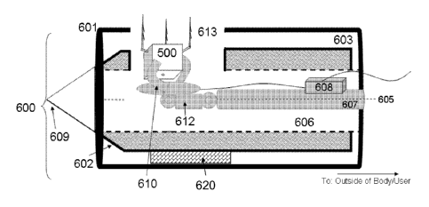
[0046] Figs. 9-11 show various embodiments of direct deployment system 600
for use in
delivering implantable device 500. In Fig. 9, direct delivery system 600
comprises intravenous
cannula 601, pushrod 607, controlled deployment mechanism 610 and implantable
device 500.
Cannula 601 is defined by a cannula lumen 603 which is a tubular passage
through cannula 601.
Cannula 601 comprises tube 604 about a longitudinal axis 605. In this
embodiment, a needle
19
CA 02879881 2015-01-05
WO 2014/006506 PCT/IB2013/001952
602 for puncturing the bodily tissues and organs is coaxially disposed in the
cannula lumen 603.
Needle 602 includes needle lumen 606 coaxially disposed within needle 602, and
a pushrod 607
having a generally cylindrical shape coaxially disposed within needle lumen
606. Pushrod 607
extends to the outside of the direct delivery system 600 at the proximal end
where it is available
for manipulation by an operator. Pushrod 607 may be advanced within the lumen
606 to extend
to the distal end 609 of the needle 602. In one embodiment, the needle may be
retracted through
the cannula 601. In an alternate embodiment, not shown in Fig. 9, the needle
may be omitted
from the direct deployment system, and the pushrod is contained within the
cannula lumen 603.
[0047] In one embodiment, the controlled deployment mechanism is a claw,
for example
as illustrated in Fig. 9. In this embodiment, pushrod 607 is separate from or
removably attached
to implantable device 500 with the claw 610, which may be controlled by the
operator. Claw
610 comprises at least one elongated grappling member 630 for frictionally and
removably
engaging implantable device 500. In this embodiment, the implantable device
500 may include
one or more tack 501 (or other attachment elements) that facilitates insertion
of the device
through inner lumen 606. Pushrod 607 may be used to force tack 501 into the
target tissue. Fig.
9 illustrates a deployment system having a force meter 608, which measures and
displays the
force applied to an object. Force meter 608 may be used to measure the amount
of force exerted
on the pushrod 607, and thus informs an operator when the tack 501 has
penetrated, for example
by showing a sudden spike and then drop in the applied force. In this regard,
the force measured
by force meter 608 may range from 1 gram to 1 kilogram. Force meter 608 may
also be used to
test the security of the tack connection, by measurement of the pulling force
that the tack 501 is
capable of resisting without becoming dislodged. Upon the proper embedding of
the implantable
CA 02879881 2015-01-05
WO 2014/006506 PCT/IB2013/001952
device, the operator then can manipulate claw mechanism 610 to release the
implantable device
and retract the pushrod.
[0048] Fig. 10 is an alternate embodiment of a direct delivery system 600
for the
implantable device 500. Fig. 10 shows cannula 601 having orifice 613 on the
wall of the cannula
601 near the distal end of direct delivery system 600, which allows the
implantable device 500 to
be deployed in a direction perpendicular to a vessel wall, and may obviate the
need to trans-
hepatically puncture the vein as further described below. In Fig. 10,
implantable device 500 has
three hinged tacks. Other numbers of hinged tacks may be used, or other
attachment elements as
described above may be substituted or used in conjunction with the tacks
described herein.
According to Fig. 10, direct delivery system 600 may be advanced via arterial
access without
losing optimal placement positioning, with the hinge 612 between pushrod 607
and claw 610 that
permits the claw 610 to be positioned at an angle with respect to the pushrod.
Hinge 612 may be
an active hinge controllable by the operator. In this embodiment, the claw is
angled at 90
degrees to the pushrod, but other angles may be possible. Thus, the
implantable device 500 may
be placed even where the cannula 601 is coaxially parallel to a vessel wall.
In this embodiment,
the system may further comprise a push component 620 which provides the
required force to
securely embed the implantable device 500 in a position perpendicular to the
vessel wall and
lateral to the axis of the cannula. For example, push component 620 may be an
expandable
balloon that, upon expansion, pushes the implantable device into the target
site. Alternatively,
push component may be composed of a shape memory element, for example, a
Nitinol spring
that may be triggered by well-known means in the art, such as heat, light,
chemical, pH,
magnetic or electrical stimuli. As in Fig. 9, force meter 608 may be used to
measure the amount
of force exerted on the pushrod 607, and thus informs an operator when the
implantable device is
21
CA 02879881 2015-01-05
WO 2014/006506 PCT/IB2013/001952
securely embedded prior to retraction. The deployment of the implantable
device in this
embodiment is not necessarily through the orifice. Optionally, the implantable
device may be
pushed out of the distal end of the cannula and/or maneuvered by hinge 12 for
the proper
orientation for implantation.
[0049] Fig. 11 shows another embodiment of a direct delivery system 600
where
implantable device 500 is securely attached to a controlled deployment
mechanism shaped as
protective inverted cone 614, which comprised of a biocompatible material. The
protective cone
in Fig. 11 may be comprised of a magnetic, mechanical, polymer or adhesive
material. In other
embodiments, the controlled deployment mechanism described in Fig. 11 need not
be cone-
shaped but may comprise any suitable shape to deliver the device.
[0050] Protective cone 614 fits complimentarily into pushrod portion 615
during
delivery. The pushrod 607 advances the implantable device 500 through the
lumen and to the
implantable site. In Fig. 11, the implantable device is advanced through the
needle lumen 600,
which is inside the cannula lumen. In an alternate embodiment, not shown, the
implantable
device may be advanced through the cannula lumen only. Further advancement of
the pushrod
insets the implantable device at the target location. Retraction of the
pushrod 607 separates the
implanted device from the protective cone 614, leaving the device at the
implantation site
provided that the device is securely embedded. In the embodiment shown in Fig.
11, the force
required to separate the protective cone 614 from the pushrod portion 615 is
less than the force
required to remove attachment element 501 from bodily tissue after secure
implantation.
Accordingly, it is a controlled amount of force that releases the implantable
device from the
controlled deployment mechanism. As stated above, the protective cone 614 may
be attached to
the pushrod portion 615 by magnetic, mechanical, polymer, or adhesive means,
for example.
22
CA 02879881 2015-01-05
WO 2014/006506 PCT/IB2013/001952
Other similar means may be used as is known in the art. Accordingly,
implantable device 500
and protective cone 614 may be deployed from direct delivery system 600 by
retracting pushrod
607 and pushrod portion 615 after securely embedding the tack 501 in the
target location. The
protective cone 614 and pushrod portion 615 may be used in place of or in
conjunction with any
embodiment of direct delivery system 600 for implanting device 500.
[0051] Fig. 11 illustrates the use of force meter 608 with the system. The
force meter is
connected to pushrod portion 615 and can measure the force used to embed the
implantable
device 500 as well as the force used to pull the implantable device from the
target location once
it is embedded. Force meter 608 is optional component of the system.
[0052] The direct deployment system described above may be used to implant
the
implantable device in any accessible vessel or non-vessel structure of the
body, such as in the
cardiovascular system, the hepatic-portal veins, the gastrointestinal tract,
the septum in the heart,
or in the parenchyma of the liver. For example, the invention may be useful in
the hepatic-portal
veins during portal venous catheterization procedures to implant the device
500 in the portal
vein. The portal vein is a vessel in the abdominal cavity that drains
deoxygenated blood to the
liver for cleaning. A system of blood vessels, the hepatic veins, removes the
cleaned blood from
the liver to the inferior vena cava, where it is returned to the heart. Portal
hypertension ("PHT")
occurs when the portal vein experiences a rise in blood pressure that may not
be a consequence
of an increase in a patient's overall systemic blood pressure. Often, PHT is
defined according to
a "portal pressure gradient or, the difference in pressure between the portal
vein and the hepatic
veins, for example of 10 mmHg or greater. A typical portal venous pressure
under normal
physiological conditions is less than or equal to approximately 10 mmHg, and
the hepatic venous
pressure gradient (HVPG) is less than approximately 5 mmHg. Increased portal
pressure leads
23
CA 02879881 2015-01-05
WO 2014/006506 PCT/IB2013/001952
to the formation of porto-systemic collaterals, including gastroesophageal
varices. Once formed,
varices represent a major risk for the patient due to the susceptibility for
rupture and subsequent
hemorrhage that in many cases leads to death. As a result, PHT is considered
one of the most
severe complications of cirrhosis of the liver and a major cause of morbidity
and mortality in
cirrhosis patients. One exemplary use the present invention is for embedding
an implantable
device to monitor PHT.
[0053] Fig. 12 is an image of the portal venous system, showing the hepatic
portal
venous system, including the right portal vein (RPV), the left portal vein
(LPV), and the main
portal vein (MPV). Preferably, the implantation zone is in the LPV location
shown in Fig. 12.
[0054] For the hepatic vein, the implantable device 500 may be inserted,
for example, by
transjugular hepatic vein access, similar to the procedure used in hepatic
vein pressure-gradient
measurements. Implantation is typically performed by an interventional
radiologist under
fluoroscopic guidance.
[0055] The procedure of deploying the direct deployment device described
above begins
with well-known means to identify and access the target location for direct
implantation. The
target location may be identified by fluoroscopy and/or ultrasound and
accessed by the well-
known access routes. For example, one route is to access the left portal vein
via the anterior
subxiphoid left route. The steps for deployment of the implanted device
include first advancing
the access set, including the cannula, through the abdomen into the left lobe
of the liver. Upon
reaching the required depth in the liver tissue, the needle may be retracted.
The target vessel is
preferably a large portal vein branch (between 4-10 mm in diameter) and is
perpendicular to the
longitudinal direction of the vessel. However, the location need not be
perpendicular to the
24
CA 02879881 2015-01-05
WO 2014/006506 PCT/IB2013/001952
longitudinal direction of the vessel where the deployment system embodiment of
Fig. 10, for
example, is used. The step of advancing the access set may comprise first
using a cannula
having a needle disposed within the cannula and protruding from the distal end
thereof to pierce
the bodily tissue, pulling back the needle so that the needle is retracted
trough the cannula, then
advancing the cannula to said target site. Alternatively, the step of
advancing the access set may
comprise using a needle separate from the cannula to pierce the bodily tissue,
removing said
needle, then introducing said cannula and advancing the cannula to said target
site.
[0056] Once the appropriate vessel location is reached, the pushrod,
controlled
deployment mechanism and implantable device is introduced into the cannula. As
described
above, the controlled deployment mechanism and implantable device is attached
to the distal end
of the pushrod, and the pushrod is inserted into the cannula. The implantable
device is distally
advanced by the pushrod. Upon reaching the distal end of the cannula, the
pushrod is further
advanced to embed the implantable device into the target site. When the
pushrod is retracted, a
controlled amount of negative (pull) force is applied, disengaging the
implantable device from
the controlled deployment mechanism and the pushrod. Then, the introducer
cannula is
removed, leaving the implantable device in the vessel. This method may be
adapted for both the
self-deploying or operator-controlled controlled deployment mechanism
described above, as well
as for other target locations outside the hepatic-portal venous system.
[0057] In another aspect of the method, once the appropriate vessel
location is reached,
the pushrod, controlled deployment mechanism and implantable device are
introduced into the
cannula. The implantable device is distally advanced with the pushrod. Upon
reaching the distal
end of the cannula, an amount of force, which, for example, can be measured by
a force meter, is
administered to advance the pushrod to ensure embedding of the implantable
device into the
CA 02879881 2016-06-07
vessel wall. When the pushrod is retracted, an amount of pulling force, which,
for example, can
be measured by a force meter, is administered to ensure that the implantable
device is securely
embedded. Next, implantable device is released from the controlled deployment
mechanism and
the pushrod is retracted. Lastly, the introducer cannula is removed, leaving
the implantable
device in the vessel. This method may be adapted for both the self-deploying
or operator-
controlled controlled deployment mechanism described above, as well as for
other target
locations outside the hepatic-portal venous system.
[0058] Any
of the methods above may be carried out using a cannula having a needle
disposed therein and protruding at the distal end of the cannula, said method
comprising the steps
of piercing the body tissue, pulling back the needle so that the needle is
retracted through the
cannula, and advancing the cannula to said target site. Alternatively, any of
the methods may be
carried out using a needle not disposed within the cannula, said method
comprising the steps of
piercing the body tissue, removing said needle, and introducing said cannula
and advancing the
cannula to said target site. In a yet further alternative, any of the methods
above may be
performed without the use of any needles, e.g., following another procedure
that has already
attained access to the target site, said method comprising the steps of
attaching the cannula to the
access means, e.g., over a guidewire having access to the target site, and
advancing the cannula
to said target site.
-26-