Note: Descriptions are shown in the official language in which they were submitted.
CA 02880073 2015-01-23
WO 2014/051858 PCT/US2013/053601
METHOD AND APPARATUS FOR COVERING A FASTENER SYSTEM
BACKGROUND INFORMATION
1. Field:
The present disclosure relates generally to covers and, in particular, to
covers
comprised of composite materials. Still more particularly, the present
disclosure relates
to a method and apparatus for covering the ends of fastener systems using
covers
comprised of composite materials selected such that the covers have electrical
properties within selected ranges.
2. Background:
Sealant materials are oftentimes used to cover and seal fastener systems. In
some cases, a sealant material is pre-molded into a cap having a shape
configured to
be installed over the end of a fastener system to cover the fastener system
and seal the
fastener system. In particular, this "cap" is used to prevent substances such
as, for
example, without limitation, air, liquid, dirt, and/or other types of
substances from
crossing the barrier formed by the cap.
Sealant materials may be used to cover and seal fastener systems in different
types of systems and structures. In some cases, at least one component in a
fastener
system is comprised of an electrically conductive material, such as, for
example, metal.
Consequently, the fastener system may be prone to voltages and currents
induced by
an electromagnetic event, such as lightning, a short circuit, or some other
type of
electromagnetic event. These induced voltages and currents may lead to
electrical
discharge in the form of electrical sparking and/or arcing.
This electrical discharge may present safety issues depending on the area
within
which the electrical discharge occurs. For example, when the electrical
discharge
occurs within a fuel tank, the electrical discharge may cause undesired
effects within the
fuel tank.
The sealant material used to cover the fastener system may be configured to
help suppress the potential for electrical discharge. However, some currently
available
sealant materials are comprised of elastomeric materials. Elastomeric
materials are
1
also referred to as elastomers. These types of sealant materials may be
referred to
as elastomeric sealants. Elastomeric sealants may be sensitive to temperature.
As
the temperature of the elastomeric sealant changes, the performance of the
elastomeric sealant with respect to suppressing the potential for electrical
discharge
may vary.
Further, pre-molding an elastomeric sealant into the shape of a cap may be
more difficult and/or time-consuming than desired. The elastomeric sealant may
also
have strength limitations. Consequently, the elastomeric sealant may need to
have a
thickness that is greater than desired to achieve suppression of the potential
for
electrical discharge. Therefore, it would be desirable to have a method and
apparatus that takes into account at least some of the issues discussed above,
as
well as other possible issues.
SUMMARY
In one embodiment, there is provided an apparatus comprising: a cover placed
over a fastener system at a surface of an object in which the fastener system
is
installed; and a sealant material applied over the fastener system and
attaching the
cover to the surface of the object, wherein the cover comprises a flange
attached to
the surface of the object by the sealant material, and a number of composite
materials selected such that the cover is configured to reduce an effect of an
electrical discharge, which occurs around the fastener system, on an
environment
outside the cover.
In another embodiment, there is provided a method for covering a fastener
system, the method comprising: placing a cover over the fastener system at a
surface
of an object in which the fastener system is installed, wherein the cover is
comprised
of a number of composite materials; reducing an effect of an electrical
discharge,
occurring around the fastener system, on an environment outside the cover
using the
cover; applying a sealant material over the fastener system at the surface of
the
object prior to placing the cover over the fastener system or applying a
sealant
material inside the cover prior to placing the cover over the fastener system;
and
attaching the flange to the surface of the object by the sealant material.
2
CA 2830073 2017-06-09
CA 02880073 2016-08-12
In a further embodiment, there is provided an apparatus comprising: a cover
comprising a unitary piece comprising a composite material, and having a shape
comprising: a cylinder portion with a dome covering a first end of the
cylinder and an
opening at the opposite end, and a flange extending radially from the
cylinder's edge
and having a surface distal to the dome which is substantially perpendicular
with the
cylinder, a sealant filling and adhering to the interior of the cover and
adhering to and
enveloping the flange, and for adhering to an exposed portion of a fastener
system;
the apparatus configured such that in operation, the cover forms a barrier
that
prevents materials released inside of the cover from entering an environment
outside
of the cover.
In a still further embodiment, there is provided an apparatus comprising: a
cover comprising a unitary piece comprising a composite material and having; a
volume resistivity of about 1.0x10⁹ ohm-meters or less when measured at 40
volts;
and a surface resistivity of about 1.0x10¹¹ ohms per square or less when
measured at
100 volts or less; and having a shape comprising a cylinder portion with a
dome
covering a first end of the cylinder and an opening at the opposite end, and a
flange
extending radially from the cylinder's edge and having a surface distal to the
dome
which is substantially perpendicular with the cylinder; a coating applied to
the cover
such that the coating dissipates static charge and reduces a level of
corrosion; a
sealant filling and adhering to the interior of the cover and adhering to and
enveloping
the flange, and for adhering to an exposed portion of a fastener system; the
apparatus configured such that in operation, the cover forms a barrier that
prevents
materials released inside of the cover from entering the environment outside
of the
cover, and such that the electrical resistivity prevents an electrical
discharge from
being conducted through the cover.
In another embodiment, an apparatus comprises a cover. The cover is
configured to be placed over a fastener system at a surface of an object in
which the
fastener system is installed. The cover is comprised of a number of composite
materials selected such that the cover is configured to reduce an effect of an
electrical discharge, which occurs around the fastener system, on an
environment
outside the cover.
2a
CA 02880073 2016-08-12
In another embodiment, a method for covering a fastener system is provided.
A cover is placed over a fastener system at a surface of an object in which
the
fastener system is installed. The cover is comprised of a number of composite
materials. An effect of an electrical discharge, occurring around the fastener
system,
on an environment outside the cover is reduced using the cover.
The features and functions can be achieved independently in various
embodiments of the present disclosure or may be combined in yet other
embodiments in which further details can be seen with reference to the
following
description and drawings.
2b
CA 02880073 2015-01-23
WO 2014/051858 PCT/US2013/053601
BRIEF DESCRIPTION OF THE DRAWINGS
The novel features believed characteristic of the illustrative embodiments are
set
forth in the appended claims. The illustrative embodiments, however, as well
as a
preferred mode of use, further objectives and features thereof, will best be
understood
by reference to the following detailed description of an illustrative
embodiment of the
present disclosure when read in conjunction with the accompanying drawings,
wherein:
Figure 1 is an illustration of an isometric view of a cover installed over a
fastener
system in accordance with an illustrative embodiment;
Figure 2 is an illustration of a cross-sectional view of a cover installed
over a
fastener system in accordance with an illustrative embodiment;
Figure 3 is an illustration of a process for installing a cover on a fastener
system
in the form of a flowchart in accordance with an illustrative embodiment;
Figure 4 is an illustration of a process for manufacturing a cover for a
fastener
system in the form of a flowchart in accordance with an illustrative
embodiment;
Figure 5 is an illustration of an aircraft manufacturing and service method in
the
form of a block diagram in accordance with an illustrative embodiment; and
Figure 6 is an illustration of an aircraft in the form of a block diagram in
accordance with an illustrative embodiment.
DETAILED DESCRIPTION
The different illustrative embodiments recognize and take into account
different
considerations. For example, the illustrative embodiments recognize and take
into
account that it may be easier and less time-consuming to form a cap for a
fastener
system that is comprised of a composite material as compared to an elastomeric
material.
Further, the illustrative embodiments recognize and take into account that a
composite material may be designed and formed to have electrical properties
with
values within selected ranges. In particular, these ranges may be selected
such that
the composite material is capable of suppressing the potential for electrical
discharge.
However, a cap formed from a composite material may be unable to provide the
quality of seal that can be provided by an elastomeric sealant. Consequently,
the
3
CA 02880073 2015-01-23
WO 2014/051858 PCT/US2013/053601
illustrative embodiments recognize and take into account that it may be
desirable to use
both an elastomeric sealant and a cap formed from a composite material to
cover the
end of a fastener system.
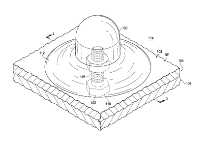
With reference now to Figure 1, an illustration of an isometric view of a
cover
installed over a fastener system is depicted in accordance with an
illustrative
embodiment. As depicted, cover 100 has been installed over fastener system
102. In
particular, cover 100 has been placed over fastener system 102 at surface 101
of object
103 in which fastener system 102 is installed.
As depicted, object 103 includes first structure 104 and second structure 106.
Fastener system 102 is being used to join first structure 104 to second
structure 106.
Depending on the implementation, a fastener system, such as fastener system
102,
may be used to join different types of structures. Each of the structures
joined by the
fastener system may take the form of, for example, without limitation, a skin
panel, a
rod, a beam, a spar, a rib, a tube, a plate, a structural assembly or some
other type of
structure.
In this illustrative example, fastener system 102 is comprised of number of
components 108. As used herein, a "number of" items may be one or more items.
In
this manner, number of components 108 may be one or more components. In this
example, number of components 108 includes bolt 110 as well as a nut (not
shown in
this view).
However, in other illustrative examples, fastener system 102 may be comprised
of a number of components that include at least one of a fastener, a washer, a
plate, a
spacer, a gasket, a buckle, a locking device, and some other type of
component. The
fastener in the number of components may be selected from one of a screw, a
nut, a
bolt, a nail, a rod, a dowel, a pin, a clamp, a grommet, a latch, a peg, a
clip, a rod, a
zipper, an anchor, a tie, a tag, and other types of fasteners.
As used herein, the phrase "at least one of", when used with a list of items,
means different combinations of one or more of the listed items may be used
and only
one of each item in the list may be needed. For example, "at least one of item
A, item
B, and item C" may include, without limitation, item A or item A and item B.
This
example also may include item A, item B, and item C or item B and item C. In
other
examples, "at least one of" may be, for example, without limitation, two of
item A, one of
4
CA 02880073 2015-01-23
WO 2014/051858 PCT/US2013/053601
item B, and ten of item C; four of item B and seven of item C; and other
suitable
combinations.
Sealant material 112 is used to attach cover 100 to surface 101 of object 103.
In
particular, sealant material 112 has adhesive properties that allow cover 100
to be
fixedly installed over fastener system 102.
Sealant material 112 may be comprised of an elastomeric material in this
depicted example. As a result, sealant material 112 may be referred to as an
elastomeric sealant. In other illustrative examples, sealant material 112 may
be
comprised of a filler material in addition to the elastomeric material. In
some cases,
sealant material 112 may be comprised of one or more of an elastomeric
material, a
resin material, an acrylic material, an elastic material, a silicone material,
a rubber
material, and other types of materials.
In this illustrative example, sealant material 112 is applied over fastener
system
102 prior to cover 100 being placed over fastener system 102. Cover 100 is
then
placed over sealant material 112. Of course, in other illustrative examples,
sealant
material 112 may be applied to an inside of cover 100 prior to cover 100 being
placed
over fastener system 102. In other words, cover 100 may be pre-filled with
sealant
material 112.
In this illustrative example, placement of cover 100 over sealant material 112
causes a portion of sealant material 112 to at least partially surround a
flange (201) (not
shown in this view) of cover 100. In other words, when cover 100 is placed
over sealant
material 112, a portion of sealant material 112 squeezes out of and around the
flange (201) of cover 100. Of course, in other illustrative examples, sealant
material
112 may not extend beyond the flange (201) of cover 100.
Cover 100 may be comprised of a number of composite materials. In this
illustrative example, cover 100 is comprised of a composite material in the
form of a
carbon fiber-reinforced plastic (CFRP) material. However, depending on the
implementation, cover 100 may be comprised of a number of composite materials
that
include at least one of a carbon fiber-reinforced plastic material, a fiber-
reinforced
polymer, a glass-reinforced plastic, an aramid fiber-reinforced material, a
metallic
material, a fiberglass material, a plastic material, a thermoplastic material,
a thermoset
material, and some other type of composite material.
5
CA 02880073 2015-01-23
WO 2014/051858 PCT/US2013/053601
In this illustrative example, cover 100 is comprised of a number of composite
materials selected to provide cover 100 with certain selected properties. For
example,
in certain situations, an electrical discharge may occur around fastener
system 102.
The electrical discharge may be, for example, without limitation, an
electrical arc or a
spark.
The electrical discharge may occur between the components that make up
fastener system 102 or between fastener system 102 and the materials that make
up
object 103. Further, the electrical discharge may occur at or around fastener
system
102 at any point along the entire length of fastener system 102. Cover 100 may
be
comprised of a number of composite materials selected such that cover 100 is
configured to reduce an effect of the electrical discharge environment 114
outside cover
100.
For example, an electrical discharge around fastener system 102 may cause a
number of materials to be released inside cover 100. These materials may
include, for
example, without limitation, a number of gases, a number of liquids, and/or a
number of
particulates. Further, these materials may be hot when released.
Cover 100 is configured to reduce an undesired release of these materials into
environment 114 outside cover 100. In other words, cover 100 forms a barrier
that
substantially prevents these materials from escaping into environment 114.
In some cases, object 103 may be a fuel tank in an aerospace vehicle and
surface 101 of object 103 may be an inner surface of the fuel tank. In this
manner,
environment 114 may be the inside chamber of the fuel tank. A release of hot
materials
inside the fuel tank may cause undesired effects within the fuel tank. Cover
100 is
configured to reduce and/or prevent the undesired release of materials into
the fuel tank
to reduce a possibility of undesired effects occurring within the fuel tank in
response to
the electrical discharge occurring around the fastener system.
Additionally, cover 100 may be comprised of a number of composite materials
selected such that cover 100 is configured to dissipate static charge. In
particular, the
number of composite materials may be selected such that at least one
electrical
property of cover 100 has a value within a range selected such that cover 100
is
capable of dissipating static charge. In other words, cover 100 may be static
dissipative. The at least one electrical property of the cover may include at
least one of
6
CA 02880073 2015-01-23
WO 2014/051858
PCT/US2013/053601
an electrical resistance of the cover, an electrical conductivity of the
cover, and an
electrical resistivity of the cover.
As used herein, the "electrical resistance" of an item is the opposition of
the item
to the flow of electric current through the item. The "electrical
conductivity" of an item is
the ability of the item to allow the flow of electric current through the
item. The
"electrical resistivity" an item is the ability of that item to prevent an
electrical current
from being conducted through the item.
In one illustrative example, cover 100 may be configured such that the
electrical
resistivity of cover 100 comprises a volume resistivity of about 1.0x10⁹ ohm-
meters (O-
m) or less when measured at about 40 volts (V) or less and/or a surface
resistivity of
about 1.0x10¹¹ ohm per square (0/sq) or less when measured at about 100 volts
(V) or
less.
In some cases, the number of composite materials from which cover 100 is
formed may be selected to reduce a level of corrosion that may occur at
surface 101 of
object 103. This corrosion may be caused by contact and/or near-contact
between
cover 100 and surface 101 of object 103.
With reference now to Figure 2, an illustration of a cross-sectional view of a
cover installed over a fastener system is depicted in accordance with an
illustrative
embodiment. In this illustrative example, a cross-sectional view of cover 100
installed
over fastener system 102 in Figure 1 is depicted taken along lines 2-2.
Cover 100 has shape 200. Shape 200 may be a bullet-type shape or conical
shape having flange 201. Flange 201 of cover 100 is surrounded and covered by
sealant material 112. Sealant material 112 attaches flange 201 to surface 101
of object
103.
Shape 200 is configured such that cover 100 may receive end 202 of fastener
system 102 and cover substantially all of exposed portion 204 of fastener
system 102.
Exposed portion 204 of fastener system 102 includes nut 206. Exposed portion
204 of
fastener system 102 is the portion of fastener system 102 that extends past
surface 101
of object 103.
Fastener system 102 is located in hole 208 in object 103. As depicted, cover
100
may be configured to substantially prevent fluid flowing through hole 208 from
flowing
into environment 114 outside cover 100. Further, cover 100 may be configured
to
substantially prevent fluid in environment 114 outside cover 100 from flowing
through
7
CA 02880073 2015-01-23
WO 2014/051858 PCT/US2013/053601
hole 208. For example, when object 103 is a fuel tank and surface 101 is an
inner
surface of the fuel tank, cover 100 substantially prevents fuel stored within
the fuel tank
from leaking outside of the fuel tank through hole 208. Similarly, cover 100
substantially
prevents fluid flowing through hole 208 from entering inside the fuel tank.
The illustrations of cover 100 and fastener system 102 in Figures 1-2 are not
meant to imply physical or architectural limitations to the manner in which an
illustrative
embodiment may be implemented. Other components in addition to or in place of
the
ones illustrated may be used. Some components may be optional.
For example, in some cases, cover 100 may have a different shape than shape
200 in Figure 2. In other illustrative examples, cover 100 may be used to
cover the
ends of two fastener systems with sealant material 112 applied over the ends
of both
fastener systems.
In still other illustrative examples, a coating may be applied to cover 100 to
provide cover 100 with the capability to dissipate static charge. In some
cases, the
coating may be applied to at least a portion of cover 100 to reduce a level of
corrosion
at surface 101 of object 103 that may be caused by cover 100.
In some illustrative examples, sealant material 112 may be applied to first
structure 104 without coming into contact with fastener system 102. For
example,
sealant material 112 may be applied in the shape of a ring around fastener
system 102.
However, sealant material 112 may be applied in a manner such that flange 201
of
cover 100 may still contact sealant material 112 when cover 100 is placed over
sealant
material 112 and fastener system 102. In these examples, sealant material 112
may be
used solely for attaching cover 100 to fastener system 102 and sealing an
interface
between cover 100 and fastener system 102.
In other illustrative examples, sealant material 112 may not be used to cover
fastener system 102. Instead, an adhesive material and/or some other type of
material
may be used to install cover 100 over fastener system 102. Depending on the
manner
in which the adhesive material and/or other materials are applied, these
materials may
not come into contact with fastener system 102.
Turning now to Figure 3, an illustration of a process for installing a cover
over a
fastener system is depicted in accordance with an illustrative embodiment. The
process
illustrated in Figure 3 may be used to install a cover, such as, for example,
without
8
CA 02880073 2015-01-23
WO 2014/051858 PCT/US2013/053601
limitation, cover 100 from Figure 1, over a fastener system, such as, for
example,
without limitation, fastener system 102 from Figure 1.
The process begins by placing a cover over a fastener system at a surface of
an
object in which the fastener system is installed (operation 300). The cover is
comprised
of a number of composite materials. In these illustrative examples, a sealant
material
may be either applied over the fastener system or applied inside the cover
prior to the
cover being placed over the fastener system. Placement of the cover over the
fastener
system may cause a portion of the sealant material to squeeze outside of a
flange of the
cover.
Thereafter, an effect of an electrical discharge, occurring around the
fastener
system, on an environment outside the cover is reduced using the cover
(operation
302), with the process terminating thereafter. In particular, in operation
302, the cover
may reduce an undesired release of a number of materials into the environment
outside
the cover in response to the electrical discharge occurring around the
fastener system.
With reference now to Figure 4, an illustration of a process for manufacturing
a
cover for a fastener system is depicted in accordance with an illustrative
embodiment.
The process illustrated in Figure 4 may be used to manufacture a cover, such
as, for
example, without limitation, cover 100 from Figure 1.
The process begins by forming a number of composite materials for use in
manufacturing the cover (operation 400). In operation 400, the number of
composite
materials may be formed according to specifications selected such that the at
least one
electrical property of the cover will have a value within a selected range.
In particular, the number of composite materials may be formed according to
specifications selected such that at least one of the electrical resistance of
the cover,
the electrical conductivity of the cover, and the electrical resistivity of
the cover has a
value within a selected range. The range may be selected such that the cover
will be
static dissipative. In this illustrative example, the number of composite
materials may
include a carbon fiber-reinforced plastic material.
Thereafter, the process manufactures the cover using the number of composite
materials (operation 402), with the process terminating thereafter. In
operation 402, the
cover is manufactured such that the cover has a shape configured to receive
the end of
the fastener system and any components of the fastener system that extend past
a
surface of the object in which the fastener system is installed.
9
CA 02880073 2015-01-23
WO 2014/051858 PCT/US2013/053601
The flowcharts and block diagrams in the different depicted embodiments
illustrate the architecture, functionality, and operation of some possible
implementations
of apparatus and methods in an illustrative embodiment. In this regard, each
block in
the flowcharts or block diagrams may represent a module, a segment, a
function, and/or
a portion of an operation or step. For example, one or more of the blocks may
be
implemented as program code, in hardware, or a combination of the program code
and
hardware. When implemented in hardware, the hardware may, for example, take
the
form of integrated circuits that are manufactured or configured to perform one
or more
operations in the flowcharts or block diagrams.
In some alternative implementations of an illustrative embodiment, the
function or
functions noted in the blocks may occur out of the order noted in the figures.
For
example, in some cases, two blocks shown in succession may be executed
substantially concurrently, or the blocks may sometimes be performed in the
reverse
order, depending upon the functionality involved. Also, other blocks may be
added in
addition to the illustrated blocks in a flowchart or block diagram.
Illustrative embodiments of the disclosure may be described in the context of
aircraft manufacturing and service method 500 as shown in Figure 5 and
aircraft 600 as
shown in Figure 6. Turning first to Figure 5, an illustration of an aircraft
manufacturing
and service method in the form of a block diagram is depicted in accordance
with an
illustrative embodiment. During pre-production, aircraft manufacturing and
service
method 500 may include specification and design 502 of aircraft 600 in Figure
6 and
material procurement 504.
During production, component and subassembly manufacturing 506 and system
integration 508 of aircraft 600 in Figure 6 takes place. Thereafter, aircraft
600 in Figure
6 may go through certification and delivery 510 in order to be placed in
service 512.
While in service 512 by a customer, aircraft 600 in Figure 6 is scheduled for
routine
maintenance and service 514, which may include modification, reconfiguration,
refurbishment, and other maintenance or service.
Each of the processes of aircraft manufacturing and service method 500 may be
performed or carried out by a system integrator, a third party, and/or an
operator. In
these examples, the operator may be a customer. For the purposes of this
description,
a system integrator may include, without limitation, any number of aircraft
manufacturers and major-system subcontractors; a third party may include,
without
CA 02880073 2015-01-23
WO 2014/051858 PCT/US2013/053601
limitation, any number of vendors, subcontractors, and suppliers; and an
operator may
be an airline, a leasing company, a military entity, a service organization,
and so on.
With reference now to Figure 6, an illustration of an aircraft in the form of
a block
diagram is depicted in which an illustrative embodiment may be implemented. In
this
example, aircraft 600 is produced by aircraft manufacturing and service method
500 in
Figure 5 and may include airframe 602 with plurality of systems 604 and
interior 606.
Examples of systems 604 include one or more of propulsion system 608,
electrical
system 610, hydraulic system 612, and environmental system 614. Any number of
other systems may be included. Although an aerospace example is shown,
different
illustrative embodiments may be applied to other industries, such as the
automotive
industry.
Apparatuses and methods embodied herein may be employed during at least
one of the stages of aircraft manufacturing and service method 500 in Figure
5. For
example, one or more covers, implemented in a manner similar to cover 100
described
in Figure 1, along with a sealant material, such as sealant material 112 in
Figure 1,
may be used to cover a corresponding one or more fastener systems for aircraft
600
during component and subassembly manufacturing 506, system integration 508,
certification and delivery 510, and/or routine maintenance and service 514.
Using these types of covers may provide the desired level of suppression of
the
potential for sparking in aircraft 600. Further, using these types of covers
may reduce
the amount of time needed for sealing and covering fastener systems for
aircraft 600 as
compared to the currently available caps pre-molded from elastonneric
sealants.
In one illustrative example, components or subassemblies produced in
component and subassembly manufacturing 506 in Figure 5 may be fabricated or
manufactured in a manner similar to components or subassemblies produced while
aircraft 600 is in service 512 in Figure 5. As yet another example, one or
more
apparatus embodiments, method embodiments, or a combination thereof may be
utilized during production stages, such as component and subassembly
manufacturing
506 and system integration 508 in Figure 5. One or more apparatus embodiments,
method embodiments, or a combination thereof may be utilized while aircraft
600 is in
service 512 and/or during maintenance and service 514 in Figure 5. The use of
a
number of the different illustrative embodiments may substantially expedite
the assembly
of and/or reduce the cost of aircraft 600.
11
CA 02880073 2015-01-23
WO 2014/051858 PCT/US2013/053601
The description of the different illustrative embodiments has been presented
for
purposes of illustration and description, and is not intended to be exhaustive
or limited
to the embodiments in the form disclosed. Many modifications and variations
will be
apparent to those of ordinary skill in the art. Further, different
illustrative embodiments
may provide different features as compared to other illustrative embodiments.
The
embodiment or embodiments selected are chosen and described in order to best
explain the principles of the embodiments, the practical application, and to
enable
others of ordinary skill in the art to understand the disclosure for various
embodiments
with various modifications as are suited to the particular use contemplated.
12