Note: Descriptions are shown in the official language in which they were submitted.
CA 02880106 2015-01-26
WO 2014/023442 PCT/EP2013/057198
1
INTERFACE STRUCTURE
The present application relates to an interface structure.
Today European patent EP I 346794B1 is known which relates to a
modular structure, particularly for mounting blanks on retainers, which
addresses the problem that arises when certain operations need to be carried
out, such as for example painting, cleaning and assembly, or the execution
of various different forms of working, such as for example removing
shavings, which require the locking of the piece and/or blank in a preset
position for the treatment thereof
Thus devices are known which are indispensable whenever the stable
locking of an object to be treated by way of generic and even simple
operations, not necessarily in a purely industrial setting, is required.
A significant drawback, which is complained of in conventional
devices, lies in the fact that in order to achieve a stable locking of the
piece
it is necessary to bring both of the spacing elements of the locking device in
contact with two opposite side faces of the same piece.
In this manner the possibility is thus ruled out of executing any work
at those side faces, which, since they are affected by the contact, have no
free surfaces to allow contact with the tool or, more generally, with the
component of any machine tool.
It follows from this that one has to subsequently remove the piece,
positioning it according to a new orientation which is such as to allow the
exposure of the two side surfaces which were earlier partially concealed by
the locking elements.
A further aggravating factor of the above problem consists in that,
during the locking of the piece, the latter has at least three surfaces at
which
no work can be performed, the third surface, in addition to the side surfaces
adjacent to the locking elements, being the lower one, which is entirely
resting on the work surface of the machine tool.
The necessity follows from this that one has to resort to multiple
CA 02880106 2015-01-26
WO 2014/023442 PCT/EP2013/057198
2
successive positionings and associated lockings of the piece, with the
further aggravating factor of possibly repeatedly making systematic
positioning errors, which thus have a negative effect on the precision that
can be achieved overall at the end of work on the piece.
Another drawback of devices lies in the necessity to avail of qualified
labor in order to be able to perform the delicate preliminary operations of
positioning and centering the piece.
An additional drawback, which often recurs in conventional locking
devices, consists in possibly damaging the piece by local deformation, at the
surfaces that have already been worked and are subsequently subjected to
contact with the brackets, in order to allow the working of surfaces of the
piece which have not yet been treated.
A significant problem, in addition to those mentioned above, relates
to the considerable expenditure of time caused by repeated, successive
operations to unlock, reposition and relock a piece that is intended to
receive some form of treatment at a plurality of surfaces.
In a partial solution to such drawbacks, EP1346794B1 claims a
modular structure, for mounting, on retainers, blanks having at least one
seat, the modular structure comprising at least one flat plate that has a
plurality of first seats for detachable connection of first fixing means for
at
least one first body and second temporary fixing means allowing detachable
connection of the first body to the blank, the second temporary fixing means
allowing connection of the modular structure at the seat formed in the blank
and further comprising a first centering bush for the automatic centering of
the first body with respect to the first seat, the first bush having a first
portion which is connectable in the first seat and a second frustum-shaped
upper portion which has an approximately frustum-shaped outer perimetric
surface that protrudes above the plate once the connection between the first
seat and the bush has been achieved. The second frustum-shaped upper
portion has a lower surface directly in contact with an upper surface of the
CA 02880106 2015-01-26
WO 2014/023442 PCT/EP2013/057198
3
flat plate; the first means for fixing the first body to the plate comprise a
first traction element for connection between the first seat and the first
body
and a first vise-like device, which is associated with the first body, so as
to
temporarily lock the first traction element. The first body, which is
cylindrical, has a second axial hole for the partial containment of the first
and/or second traction elements, and comprises, in a lower region, a third
through hole that is formed radially and is meant to accommodate the first
vise-like device, the third hole affecting the second axial hole approximately
at right angles. The first vise-like device is constituted by a pair of first
jaws, which can be accommodated inside the third hole and are arranged
mirror-symmetrically in mutually diametrically opposite positions, and the
first jaws, which are substantially cylindrical, are mutually associable by
way of activation means, which are constituted by a first screw, which is
arranged coaxially to a fourth hole and a fifth hole which are through holes
and are formed axially along the pair of first jaws.
This solution, although solving the above-mentioned problems, also
has drawbacks in that it has been found that in the parts to be fixed, and
thus
in the blanks (designated with 50 in EP1346794B ), a first threaded hole
(designated with 36 in EP1346794B1) is obtained for a fastening element
(such as a threaded shank, designated with 39a in EP1346794B1) and thus a
first seat (designated with 34 in EP1346794B1) for a centering bush
(designated with 37 in EP1346794B1): in the course of the production
process of the part to be fixed, some working steps can cause the geometric
shape of the piece to vary, since the first seat may subsequently be
recentered with a greater size and in the best adapted position for the
centering of the part (slightly shifted from the previous one).
It follows from this that the diameters of the first hole and of the first
seat do not have the same axis.
The same applicant, in a partial solution to the above-mentioned
problems, filed, on 11/7/2012, Italian application no. TV2012A000129
CA 02880106 2015-01-26
WO 2014/023442 PCT/EP2013/057198
4
relating to a device for compensating the misalignment in automatic locking
systems for mounting, on retainers, blanks which have a first hole, for a
fastening element, at the end of which a first seat for a centering bush is
provided. The device is constituted by a box-like body composed of a T-
shaped hollow body and by a U-shaped base which form an inner seat for a
truncated pyramid shaped jacket, arranged coaxially at the shank of the
hollow body and above a piston, having the capability to move transversely
with respect to the shank. A traction element is slideably arrangeable in the
shank of the hollow body and axially integral with the fixing element and
with which the centering bush is coaxially associated in an upper region and
can be arranged at the first seat which has a diameter that exceeds the
diameter of the first fixing hole and is provided eccentrically with respect
to
the latter. The traction element selectively cooperates with spheres that can
be accommodated inside adapted openings provided in the shank and inside
adapted second seats which are provided in the jacket. Between the head of
the hollow body and the jacket elastically compressible elements are
provided, means being present for allowing a temporary axial movement of
the piston.
Such solution, differently from the known art explained in which
there is a mechanical interconnection of the various components which are
mutually axially arrangeable in a stable condition, makes it possible, thanks
to the presence of the piston, to achieve an adjustment of the position
through the use of pneumatic means which are allowed to perform an axial
movement with respect to the various components.
Such solution has been provided in order to enable the fixing both of
pieces and of pallets, which are handled in automated environments.
Although such two solutions make it possible to position and stably
lock the pieces on the platfottn of any machine tool so as to perform the
desired workings, it has been found that the two solutions must be usable
separately: the first for manually locking pieces and the second for
CA 02880106 2015-01-26
WO 2014/023442 PCT/EP2013/057198
automatically locking them.
The two solutions cannot be used in conjunction on the same
platform, owing to their mechanical diversity, which makes them
incompatible.
5 The main
aim of the present invention is therefore to solve the above-
mentioned technical problems, eliminating the drawbacks in the cited
known art and hence providing an interface structure that makes it possible
to use, in conjunction and on the same platform, both of the solutions
explained above for the purpose of achieving the centering and the stable
fixing of pieces to be worked on the platform of any machine tool while at
the same time being able to vary both the height of positioning of the pieces
and that of the pallets on which they are to be positioned.
Another object of the invention is to provide an interface structure
that, in addition to the foregoing characteristics, is also low-cost and can
be
implemented with usual and conventional machinery and plants.
This aim and these and other objects which will become more
apparent hereinafter are achieved by an interface structure 1, characterized
in that it is constituted by a first, U-shaped toothed pivot 2, which can be
associated in an upper region, by way of a jaw connection, with a means of
fixing 7 with the interposition of a first bush 6 for centering, said first
toothed pivot 2 being axially integral in a lower region with a fastening
element 14 that can be associated with an underlying device 18 for
compensating the misalignment in automatic locking systems for the
mounting of blanks.
Further characteristics and advantages of the invention will become
more apparent from the detailed description of a particular, but not
exclusive, embodiment, illustrated by way of non-limiting example in the
accompanying drawings wherein:
Figure 1 is a three-quarters view from the side, plus an exploded view,
of the invention associated both with a means of fixing and with a device for
CA 02880106 2015-01-26
WO 2014/023442 PCT/EP2013/057198
6
compensating the misalignment in automatic locking systems for the
mounting of blanks;
Figure 2 is a three-quarters view from the side of the invention;
Figure 3 is a three-quarters view from the side of the invention
without the bush;
Figure 4 is a three-quarters view from the side of the bush that can be
associated coaxially with the first pivot;
Figure 5 is an exploded view of the invention and the means of fixing
and the device for compensating the misalignment in automatic locking
systems for the mounting of blanks;
Figure 6 is an exploded view of the device for compensating the
misalignment in automatic locking systems for the mounting of blanks;
Figure 7 is a diametrical sectional view of the device for
compensating the misalignment in automatic locking systems for the
mounting of blanks.
In the embodiments illustrated, individual characteristics shown in
relation to specific examples may in reality be interchanged with other,
different characteristics, existing in other embodiments.
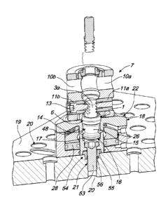
With reference to the figures, the reference numeral 1 generally
designates an interface structure that is constituted by a first U-shaped
pivot
2 so as to define a first wing 3a and a second wing 3b between which an
opening 4 is defined.
At the side surfaces of each one of the first wing 3a and the second
wing 3b there is a series of teeth 5a and 5b that protrude on the same plane.
A first centering bush 6, which is cylindrical with an external profile
with a double taper, can be inserted axially onto the first pivot 2 and can be
arranged in a stable condition below the side surfaces of each one of the
first wing 3a and the second wing 3b, and at an annular ridge 6a.
The first pivot 2 can be associated with a means of fixing 7
constituted by a pair of cylindrical elements, which are identical and
CA 02880106 2015-01-26
WO 2014/023442 PCT/EP2013/057198
7
mutually coupled, each one of which is provided with a first axial hole 8,
and transversely to the side surface 9 of each one of which, along the same
axis, two first seats 10a and 10b for means of jaw coupling with the first
pivot 2 are provided.
The function of the first bush 6 is, thanks to the double taper, to
enable an adaptation of the position of the means of fixing 7 with respect to
the first pivot 2.
The jaw coupling means are constituted by two barrels 1 la and llb
which are slidingly associable inside the first seats 10a and 10b and at one
end of which a complementary toothing 12a and 12b is provided which is
adapted to engage the series of teeth 5a and 5b.
The clamping of the two barrels 1 la and lib occurs by way of an
adapted screw 13.
Below the first bush 6, the first pivot 2 is rendered axially integral in a
lower region with a fastening element 14 that is constituted by a traction
element provided with a conical body 15 the end tip 16 of which, which is
directed away from the first pivot 2, has an expansion 17.
The fastening element 14 is associable with an underlying device 18
for compensating the misalignment in automatic locking systems for the
mounting of blanks to a plate 19, the plate 19 being provided with a series
of threaded second holes 20, which are seats for a second pivot 21 which
comprises a complementary threaded first shank 53 coaxially to which a
second centering bush 54 is arranged.
The second centering bush 54 has a frustum-shaped upper portion 55
and a cylindrical lower portion 56.
A similar third bush 57 is arranged at the end of the means of fixing 7
which does not interact with the first pivot 2.
The second pivot 21 enables the interconnection of the device 18 and
the plate 19.
The device 18 is constituted by a box-like body 22 that is composed
CA 02880106 2015-01-26
WO 2014/023442 PCT/EP2013/057198
8
of a T-shaped hollow body 23 and by a U-shaped base 24 which form a
second, inner seat 25 for a truncated pyramid shaped jacket 26 that is
arranged coaxially to the second shank 27 of said hollow body 23 and above
a piston 28 with the possibility of transverse movement with respect to said
second shank 27.
At the upper surface 29 of the base 24 there is a first annular groove
30 which acts as a seat for a first gasket 31 that is adapted to provide a
seal
at the lower perimetric edge 32 of the head 33 of the hollow body 23.
The length of the second shank 27 is such that its lower end 34 is
positioned substantially at the plane of arrangement of the lower surface 35
of the base 24.
The base 24 has, at the lower surface 34, a second hole 36 within
which the lower end 34 of the second shank 27 of the hollow body 23
operates.
A second gasket 37 is also present which can be arranged at a second
annular groove 38 that is formed in the first wall 39 of the hollow body 23,
which is formed by the second hole 36.
Proximate to the lower end 34 of the hollow body 23, there is a third
seat 40a, for the second centering bush 54, which is contiguous with an
additional seat 40b for the head of the second pivot 21.
In the second shank 27 of the hollow body 23 there are adapted
openings 41 which are substantially circular in plan view and arranged on a
same plane which is transverse to the second shank 27.
Such openings 41 are provided proximate to the open upper end 42 of
the hollow body 23.
Adapted spheres 43 are selectively arrangeable inside the openings 41
and do not have the possibility of falling into the second shank 27.
The truncated pyramid shaped jacket 26 is axially perforated in order
to pennit the passage of the shank 27 of the hollow body 23, the jacket 26
.. being provided with a second wall 44, facing toward the second shank 27, in
CA 02880106 2015-01-26
WO 2014/023442 PCT/EP2013/057198
9
which fourth seats 45 are provided.
Such spheres 43 can be selectively accommodated within the fourth
seats 45 when the fourth seats 45 are arranged on the same plane on which
the openings 41 are formed in the second shank 27 of the hollow body 23.
Between the head 33 of the hollow body 23 and the upper surface 46
of the jacket 26 there are fifth seats 47 for elastically compressible
elements
48 such as cylindrical compression springs.
The jacket 26 is of such size as to be capable of being subjected to a
transverse movement inside the inner seat 25 of the box-like body 22; the
jacket 26 is thus able to perform a movement with respect to the second
shank 27 in the sense that its second wall 44 can move toward or away from
the second shank 27.
The piston 28 is constituted by a pulley-shaped element which is
arranged in the space between the second shank 27 of the hollow body 23
and the inner side surface 58 of the base 23.
The seal is made possible by the presence of a pair of third gaskets
49a and 49b which are provided at complementarily shaped third annular
grooves 50a and 50b.
The pair of third gaskets forms means that are adapted to enable a
temporary axial movement of the piston.
Adapted screws 51 are provided which are adapted to mutually fasten
and fix the base 24 and the hollow body 23.
In the operation of the device 18, initially it is filled, at an adapted
first channel 52 that is provided proximate to the lower surface 35 of the
base 24, with air under pressure which affects the part of the inner seat 25
of
the box-like body 22 underlying the piston 28.
The air lifts the piston 28 and as a consequence also the jacket 26,
thus compressing the elastically compressible elements 48.
In this manner the spheres 43 are free to move inside the openings 41
and thus also toward the fourth seats 45.
10
At this point the fastening element 14 of the first pivot 2 is inserted
into the box-like body 22 through the open upper end 42 of the hollow body
23 until the end tip 16 and thus the expansion 17 is positioned at or slightly
below the openings 41 which are provided in the second shank 27.
When the air pressure is released, the elastically compressible
elements 48 push the jacket 26 and the piston 28 downward: in this manner
the spheres 43 are pushed by the jacket 26 so as to exit from the fourth seats
45 and thus exit slightly from the second openings 41 so as to affect the
connection zone between the conical body 15 and the end tip 16.
In this manner the fastening element 14 is placed in downward
traction.
Since the jacket 26 can move horizontally, it follows from this that the
misalignment of the fastening element 14 with respect to the first centering
bush 6 can be accepted.
The possibility offered to the jacket 26 of moving in the inner seat 25
and thus with respect to the second shank 27 of the hollow body 23 makes it
possible to accept such misalignment, by compensating it.
In practice it has been found that the invention has fully achieved the
intended aim and objects, an interface structure having been obtained that can
be used on the same platform, both for manually locking both pieces and
pallets, and for achieving such locking automatically.
Naturally the materials used as well as the dimensions of the
individual components of the invention may be more pertinent to specific
requirements.
The various means of achieving certain different functions certainly
need not coexist only in the embodiment shown, but may be present in many
embodiments, even if they are not shown.
The characteristics indicated above as advantageous, convenient or
CA 2880106 2019-05-10
11
similar, may also be missing or be substituted by equivalent characteristics.
Where technical features mentioned in any claim are followed by
reference signs, those reference signs have been included for the sole purpose
of increasing the intelligibility of the claims and accordingly, such
reference
signs do not have any limiting effect on the interpretation of each element
identified by way of example by such reference signs.
CA 2880106 2019-05-10