Note: Descriptions are shown in the official language in which they were submitted.
CA 02880325 2015-01-29
274364
A LINEAR COMPRESSOR
FIELD OF THE INVENTION
[0001] The present subject matter relates generally to linear compressors,
e.g., for
refrigerator appliances.
BACKGROUND OF THE INVENTION
[0002] Certain refrigerator appliances include sealed systems for cooling
chilled
chambers of the refrigerator appliance. The sealed systems generally include a
compressor that generates compressed refrigerant during operation of the
sealed system.
The compressed refrigerant flows to an evaporator where heat exchange between
the
chilled chambers and the refrigerant cools the chilled chambers and food items
located
therein.
[0003] Recently, certain refrigerator appliances have included linear
compressors for
compressing refrigerant. Linear compressors generally include a piston and a
driving coil.
The driving coil receives a current that generates a force for sliding the
piston forward
and backward within a chamber. During motion of the piston within the chamber,
the
piston compresses refrigerant. However, friction between the piston and a wall
of the
chamber can negatively affect operation of the linear compressors if the
piston is not
suitably aligned within the chamber. In particular, friction losses due to
rubbing of the
piston against the wall of the chamber can negatively affect an efficiency of
an associated
refrigerator appliance.
[0004] The driving coil generally engages a magnet on a mover assembly of
the
linear compressor in order to reciprocate the piston within the chamber. The
magnet is
spaced apart from the driving coil by an air gap. In certain linear
compressors, an
additional air gap is provided at an opposite side of the magnet, e.g.,
between the magnet
and an inner back iron of the linear compressor. However, multiple air gaps
can
1
CA 02880325 2015-01-29
274364
negatively affect operation of the linear compressor by interrupting
transmission of a
magnetic field from the driving coil. In addition, maintaining a uniform air
gap between
the magnet and the driving coil and/or inner back iron can be difficult.
[0005] Accordingly, a linear compressor with features for limiting friction
between a
piston and a wall of a cylinder during operation of the linear compressor
would be useful.
In addition, a linear compressor with features for maintaining uniformity of
an air gap
between a magnet and a driving coil of the linear compressor would be useful.
In
particular, a linear compressor having only a single air gap would be useful.
BRIEF DESCRIPTION OF THE INVENTION
[0006] The present subject matter provides a linear compressor. The linear
compressor includes a casing and a machined spring. An inner back iron
assembly is
fixed to the machined spring at a middle portion of the machined spring. A
driving coil is
operable to move the inner back iron assembly in order to reciprocate a piston
within a
chamber of a cylinder assembly. Additional aspects and advantages of the
invention will
be set forth in part in the following description, or may be apparent from the
description,
or may be learned through practice of the invention.
[0007] In a first exemplary embodiment, a linear compressor is provided.
The linear
compressor includes a driving coil. An inner back iron assembly is positioned
in the
driving coil. The inner back iron assembly extends between a first end portion
and a
second end portion. The inner back iron assembly includes an outer cylinder
and a sleeve.
The outer cylinder having an outer surface and an inner surface positioned
opposite each
other. The sleeve is mounted to the outer cylinder at the inner surface of the
outer
cylinder. A magnet is mounted to the inner back iron assembly at the outer
surface of the
inner back iron assembly such that the magnet faces the driving coil. The
linear
compressor also includes a machined spring. The machined spring includes a
first
cylindrical portion positioned adjacent the first end portion of the inner
back iron
assembly. A second cylindrical portion is positioned within and fixed to the
inner back
2
CA 02880325 2015-01-29
274364
iron assembly. The sleeve extends between the inner surface of the outer
cylinder and the
second cylindrical portion in order to fix the sleeve to the outer cylinder. A
first helical
portion extends between and couples the first and second cylindrical portions
together. A
third cylindrical portion is positioned adjacent the second end portion of the
inner back
iron assembly. A second helical portion extends between and couples the second
and
third cylindrical portions together.
[0008] In a second exemplary embodiment, a linear compressor is provided.
The
linear compressor defines a radial direction, a circumferential direction and
an axial
direction. The linear compressor includes a machined spring. An inner back
iron
assembly extends about the machined spring along the circumferential
direction. The
inner back iron assembly includes an outer cylinder and a sleeve. The outer
cylinder has
an outer surface and an inner surface spaced apart from each other along the
radial
direction. The sleeve is positioned at the inner surface of the outer
cylinder. The sleeve
extends between the inner surface of the outer cylinder and a middle portion
of the
machined spring along the radial direction. A driving coil extends about the
inner iron
assembly along the circumferential direction. The driving coil is operable to
move the
inner back iron assembly along an axis during operation of the driving coil. A
magnet is
mounted to the inner back iron assembly such that the magnet is spaced apart
from the
driving coil by an air gap along the radial direction.
[0009] In a third exemplary embodiment, a method for making an inner back
iron
assembly for a linear compressor is provided. The method includes forming a
plurality of
laminations into a cylindrical shape, securing the laminations of the
plurality of
laminations together in order to form an outer cylinder of the inner back iron
assembly,
inserting a sleeve into the outer cylinder such that the sleeve is positioned
on an inner
surface of the outer cylinder, welding the sleeve to the outer cylinder, and
attaching a
middle portion of a machined spring to the sleeve.
[0010] These and other features, aspects and advantages of the present
invention will
become better understood with reference to the following description and
appended
3
CA 02880325 2015-01-29
274364
claims. The accompanying drawings, which are incorporated in and constitute a
part of
this specification, illustrate embodiments of the invention and, together with
the
description, erve to explain the principles of the invention.
BRIEF DESCRIPTION OF THE DRAWINGS
[0011] A full and enabling disclosure of the present invention, including
the best
mode thereof, directed to one of ordinary skill in the art, is set forth in
the specification,
which makes reference to the appended figures.
[0012] FIG. 1 is a front elevation view of a refrigerator appliance
according to an
exemplary embodiment of the present subject matter.
[0013] FIG. 2 is schematic view of certain components of the exemplary
refrigerator
appliance of FIG. 1.
[0014] FIG. 3 provides a perspective view of a linear compressor according
to an
exemplary embodiment of the present subject matter.
[0015] FIG. 4 provides a side section view of the exemplary linear
compressor of
FIG. 3.
[0016] FIG. 5 provides an exploded view of the exemplary linear compressor
of FIG.
4.
[0017] FIG. 6 provides a side section view of certain components of the
exemplary
linear compressor of FIG. 3.
[0018] FIG. 7 provides a perspective view of a machined spring of the
exemplary
linear compressor of FIG. 3.
[0019] FIG. 8 provides a perspective view of a piston flex mount of the
exemplary
linear compressor of FIG. 3.
4
CA 02880325 2015-01-29
274364
[0020] FIG. 9 provides a perspective view of a piston of the exemplary
linear
compressor of FIG. 3.
[0021] FIG. 10 provides a perspective view of a compliant coupling of the
exemplary
linear compressor of FIG. 3.
[0022] FIG. 11 provides a perspective view of an inner back iron assembly
of the
exemplary linear compressor of FIG. 3.
[0023] FIG. 12 provides a top, plan view of the inner back iron assembly of
FIG. 11.
[0024] FIG. 13 provides a section view of the inner back iron assembly of
FIG. 11.
DETAILED DESCRIPTION
[0025] Reference now will be made in detail to embodiments of the
invention, one or
more examples of which are illustrated in the drawings. Each example is
provided by
way of explanation of the invention, not limitation of the invention. In fact,
it will be
apparent to those skilled in the art that various modifications and variations
can be made
in the present invention without departing from the scope of the invention.
For instance,
features illustrated or described as part of one embodiment can be used with
another
embodiment to yield a still further embodiment. Thus, it is intended that the
present
invention covers such modifications and variations as come within the scope of
the
appended claims and their equivalents.
[0026] FIG. 1 depicts a refrigerator appliance 10 that incorporates a
sealed
refrigeration system 60 (FIG. 2). It should be appreciated that the term "
refrigerator
appliance" is used in a generic sense herein to encompass any manner of
refrigeration
appliance, such as a freezer, refrigerator/freezer combination, and any style
or model of
conventional refrigerator. In addition, it should be understood that the
present subject
matter is not limited to use in appliances. Thus, the present subject matter
may be used
for any other suitable purpose, such as vapor compression within air
conditioning units or
air compression within air compressors.
CA 02880325 2015-01-29
274364
[0027] In the illustrated exemplary embodiment shown in FIG. 1, the
refrigerator
appliance 10 is depicted as an upright refrigerator having a cabinet or casing
12 that
defines a number of internal chilled storage compartments. In particular,
refrigerator
appliance 10 includes upper fresh-food compartments 14 having doors 16 and
lower
freezer compartment 18 having upper drawer 20 and lower drawer 22. The drawers
20
and 22 are "pull-out" drawers in that they can be manually moved into and out
of the
freezer compartment 18 on suitable slide mechanisms.
[0028] FIG. 2 is a schematic view of certain components of refrigerator
appliance 10,
including a sealed refrigeration system 60 of refrigerator appliance 10. A
machinery
compartment 62 contains components for executing a known vapor compression
cycle
for cooling air. The components include a compressor 64, a condenser 66, an
expansion
device 68, and an evaporator 70 connected in series and charged with a
refrigerant. As
will be understood by those skilled in the art, refrigeration system 60 may
include
additional components, e.g., at least one additional evaporator, compressor,
expansion
device, and/or condenser. As an example, refrigeration system 60 may include
two
evaporators.
[0029] Within refrigeration system 60, refrigerant flows into compressor
64, which
operates to increase the pressure of the refrigerant. This compression of the
refrigerant
raises its temperature, which is lowered by passing the refrigerant through
condenser 66.
Within condenser 66, heat exchange with ambient air takes place so as to cool
the
refrigerant. A fan 72 is used to pull air across condenser 66, as illustrated
by arrows Ac,
so as to provide forced convection for a more rapid and efficient heat
exchange between
the refrigerant within condenser 66 and the ambient air. Thus, as will be
understood by
those skilled in the art, increasing air flow across condenser 66 can, e.g.,
increase the
efficiency of condenser 66 by improving cooling of the refrigerant contained
therein.
[0030] An expansion device (e.g., a valve, capillary tube, or other
restriction device)
68 receives refrigerant from condenser 66. From expansion device 68, the
refrigerant
enters evaporator 70. Upon exiting expansion device 68 and entering evaporator
70, the
6
CA 02880325 2015-01-29
274364
refrigerant drops in pressure. Due to the pressure drop and/or phase change of
the
refrigerant, evaporator 70 is cool relative to compartments 14 and 18 of
refrigerator
appliance 10. As such, cooled air is produced and refrigerates compartments 14
and 18 of
refrigerator appliance 10. Thus, evaporator 70 is a type of heat exchanger
which transfers
heat from air passing over evaporator 70 to refrigerant flowing through
evaporator 70.
[0031] Collectively, the vapor compression cycle components in a
refrigeration
circuit, associated fans, and associated compartments are sometimes referred
to as a
sealed refrigeration system operable to force cold air through compartments
14, 18 (FIG.
1). The refrigeration system 60 depicted in FIG. 2 is provided by way of
example only.
Thus, it is within the scope of the present subject matter for other
configurations of the
refrigeration system to be used as well.
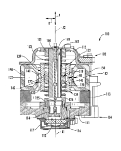
[0032] FIG. 3 provides a perspective view of a linear compressor 100
according to an
exemplary embodiment of the present subject matter. FIG. 4 provides a side
section view
of linear compressor 100. FIG. 5 provides an exploded side section view of
linear
compressor 100. As discussed in greater detail below, linear compressor 100 is
operable
to increase a pressure of fluid within a chamber 112 of linear compressor 100.
Linear
compressor 100 may be used to compress any suitable fluid, such as refrigerant
or air. In
particular, linear compressor 100 may be used in a refrigerator appliance,
such as
refrigerator appliance 10 (FIG. 1) in which linear compressor 100 may be used
as
compressor 64 (FIG. 2). As may be seen in FIG. 3, linear compressor 100
defines an
axial direction A, a radial direction R and a circumferential direction C.
Linear
compressor 100 may be enclosed within a hermetic or air-tight shell (not
shown). The
hermetic shell can, e.g., hinder or prevent refrigerant from leaking or
escaping from
refrigeration system 60.
[0033] Turning now to FIG. 4, linear compressor 100 includes a casing 110
that
extends between a first end portion 102 and a second end portion 104, e.g.,
along the
axial direction A. Casing 110 includes various static or non-moving structural
components of linear compressor 100. In particular, casing 110 includes a
cylinder
7
CA 02880325 2015-01-29
274364
assembly 111 that defines a chamber 112. Cylinder assembly 111 is positioned
at or
adjacent second end portion 104 of casing 110. Chamber 112 extends
longitudinally
along the axial direction A. Casing 110 also includes a motor mount mid-
section 113 and
an end cap 115 positioned opposite each other about a motor. A stator, e.g.,
including an
outer back iron 150 and a driving coil 152, of the motor is mounted or secured
to casing
110, e.g., such that the stator is sandwiched between motor mount mid-section
113 and
end cap 115 of casing 110. Linear compressor 100 also includes valves (such as
a
discharge valve assembly 117 at an end of chamber 112) that permit refrigerant
to enter
and exit chamber 112 during operation of linear compressor 100.
[0034] A piston assembly 114 with a piston head 116 is slidably received
within
chamber 112 of cylinder assembly 111. In particular, piston assembly 114 is
slidable
along a first axis Al within chamber 112. The first axis Al may be
substantially parallel
to the axial direction A. During sliding of piston head 116 within chamber
112, piston
head 116 compresses refrigerant within chamber 112. As an example, from a top
dead
center position, piston head 116 can slide within chamber 112 towards a bottom
dead
center position along the axial direction A, i.e., an expansion stroke of
piston head 116.
When piston head 116 reaches the bottom dead center position, piston head 116
changes
directions and slides in chamber 112 back towards the top dead center
position, i.e., a
compression stroke of piston head 116. It should be understood that linear
compressor
100 may include an additional piston head and/or additional chamber at an
opposite end
of linear compressor 100. Thus, linear compressor 100 may have multiple piston
heads in
alternative exemplary embodiments.
[0035] Linear compressor 100 also includes an inner back iron assembly 130.
Inner
back iron assembly 130 is positioned in the stator of the motor. In
particular, outer back
iron 150 and/or driving coil 152 may extend about inner back iron assembly
130, e.g.,
along the circumferential direction C. Inner back iron assembly 130 extends
between a
first end portion 132 and a second end portion 134, e.g., along the axial
direction A.
8
CA 02880325 2015-01-29
274364
[0036] Inner back iron assembly 130 also has an outer surface 137. At least
one
driving magnet 140 is mounted to inner back iron assembly 130, e.g., at outer
surface 137
of inner back iron assembly 130. Driving magnet 140 may face and/or be exposed
to
driving coil 152. In particular, driving magnet 140 may be spaced apart from
driving coil
152, e.g., along the radial direction R by an air gap AG. Thus, the air gap AG
may be
defined between opposing surfaces of driving magnet 140 and driving coil 152.
Driving
magnet 140 may also be mounted or fixed to inner back iron assembly 130 such
that an
outer surface 142 of driving magnet 140 is substantially flush with outer
surface 137 of
inner back iron assembly 130. Thus, driving magnet 140 may be inset within
inner back
iron assembly 130. In such a manner, the magnetic field from driving coil 152
may have
to pass through only a single air gap (e.g., air gap AG) between outer back
iron 150 and
inner back iron assembly 130 during operation of linear compressor 100, and
linear
compressor 100 may be more efficient than linear compressors with air gaps on
both
sides of a driving magnet.
[0037] As may be seen in FIG. 4, driving coil 152 extends about inner back
iron
assembly 130, e.g., along the circumferential direction C. Driving coil 152 is
operable to
move the inner back iron assembly 130 along a second axis A2 during operation
of
driving coil 152. The second axis may be substantially parallel to the axial
direction A
and/or the first axis Al. As an example, driving coil 152 may receive a
current from a
current source (not shown) in order to generate a magnetic field that engages
driving
magnet 140 and urges piston assembly 114 to move along the axial direction A
in order
to compress refrigerant within chamber 112 as described above and will be
understood by
those skilled in the art. In particular, the magnetic field of driving coil
152 may engage
driving magnet 140 in order to move inner back iron assembly 130 along the
second axis
A2 and piston head 116 along the first axis Al during operation of driving
coil 152.
Thus, driving coil 152 may slide piston assembly 114 between the top dead
center
position and the bottom dead center position, e.g., by moving inner back iron
assembly
130 along the second axis A2, during operation of driving coil 152.
9
CA 02880325 2015-01-29
274364
[0038] Linear compressor 100 may include various components for permitting
and/or
regulating operation of linear compressor 100. In particular, linear
compressor 100
includes a controller (not shown) that is configured for regulating operation
of linear
compressor 100. The controller is in, e.g., operative, communication with the
motor, e.g.,
driving coil 152 of the motor. Thus, the controller may selectively activate
driving coil
152, e.g., by supplying current to driving coil 152, in order to compress
refrigerant with
piston assembly 114 as described above.
[0039] The controller includes memory and one or more processing devices
such as
microprocessors, CPUs or the like, such as general or special purpose
microprocessors
operable to execute programming instructions or micro-control code associated
with
operation of linear compressor 100. The memory can represent random access
memory
such as DRAM, or read only memory such as ROM or FLASH. The processor executes
programming instructions stored in the memory. The memory can be a separate
component from the processor or can be included onboard within the processor.
Alternatively, the controller may be constructed without using a
microprocessor, e.g.,
using a combination of discrete analog and/or digital logic circuitry (such as
switches,
amplifiers, integrators, comparators, flip-flops, AND gates, and the like) to
perform
control functionality instead of relying upon software.
[0040] Linear compressor 100 also includes a machined spring 120. Machined
spring
120 is positioned in inner back iron assembly 130. In particular, inner back
iron assembly
130 may extend about machined spring 120, e.g., along the circumferential
direction C.
Machined spring 120 also extends between first and second end portions 102 and
104 of
casing 110, e.g., along the axial direction A. Machined spring 120 assists
with coupling
inner back iron assembly 130 to casing 110, e.g., cylinder assembly 111 of
casing 110. In
particular, inner back iron assembly 130 is fixed to machined spring 120 at a
middle
portion 119 of machined spring 120 as discussed in greater detail below.
[0041] During operation of driving coil 152, machined spring 120 supports
inner
back iron assembly 130. In particular, inner back iron assembly 130 is
suspended by
CA 02880325 2015-01-29
274364
machined spring 120 within the stator of the motor such that motion of inner
back iron
assembly 130 along the radial direction R is hindered or limited while motion
along the
second axis A2 is relatively unimpeded. Thus, machined spring 120 may be
substantially
stiffer along the radial direction R than along the axial direction A. In such
a manner,
machined spring 120 can assist with maintaining a uniformity of the air gap AG
between
driving magnet 140 and driving coil 152, e.g., along the radial direction R,
during
operation of the motor and movement of inner back iron assembly 130 on the
second axis
A2. Machined spring 120 can also assist with hindering side pull forces of the
motor
from transmitting to piston assembly 114 and being reacted in cylinder
assembly 111 as a
friction loss.
[0042] FIG. 6 provides a side section view of certain components of linear
compressor 100. FIG. 7 provides a perspective view of machined spring 120. As
may be
seen in FIG. 7, machined spring 120 includes a first cylindrical portion 121,
a second
cylindrical portion 122, a first helical portion 123, a third cylindrical
portion 125 and a
second helical portion 126. First helical portion 123 of machined spring 120
extends
between and couples first and second cylindrical portions 121 and 122 of
machined
spring 120, e.g., along the axial direction A. Similarly, second helical
portion 126 of
machined spring 120 extends between and couples second and third cylindrical
portions
122 and 125 of machined spring 120, e.g., along the axial direction A.
[0043] Turning back to FIG. 4. first cylindrical portion 121 is mounted or
fixed to
casing 110 at first end portion 102 of casing 110. Thus, first cylindrical
portion 121 is
positioned at or adjacent first end portion 102 of casing 110. Third
cylindrical portion
125 is mounted or fixed to casing 110 at second end portion 104 of casing 110,
e.g., to
cylinder assembly 111 of casing 110. Thus, third cylindrical portion 125 is
positioned at
or adjacent second end portion 104 of casing 110. Second cylindrical portion
122 is
positioned at middle portion 119 of machined spring 120. In particular, second
cylindrical portion 122 is positioned within and fixed to inner back iron
assembly 130.
11
CA 02880325 2015-01-29
274364
Second cylindrical portion 122 may also be positioned equidistant from first
and third
cylindrical portions 121 and 125, e.g., along the axial direction A.
[0044] First cylindrical portion 121 of machined spring 120 is mounted to
casing 110
with fasteners (not shown) that extend though end cap 115 of casing 110 into
first
cylindrical portion 121. In alternative exemplary embodiments, first
cylindrical portion
121 of machined spring 120 may be threaded, welded, glued, fastened, or
connected via
any other suitable mechanism or method to casing 110. Third cylindrical
portion 125 of
machined spring 120 is mounted to cylinder assembly 111 at second end portion
104 of
casing 110 via a screw thread of third cylindrical portion 125 threaded into
cylinder
assembly 111. In alternative exemplary embodiments, third cylindrical portion
125 of
machined spring 120 may be welded, glued, fastened, or connected via any other
suitable
mechanism or method, such as an interference fit, to casing 110.
[0045] As may be seen in FIG. 7, first helical portion 123 extends, e.g.,
along the
axial direction A, between first and second cylindrical portions 121 and 122
and couples
first and second cylindrical portions 121 and 122 together. Similarly, second
helical
portion 126 extends, e.g., along the axial direction A, between second and
third
cylindrical portions 122 and 125 and couples second and third cylindrical
portions 122
and 125 together. Thus, second cylindrical portion 122 is suspended between
first and
third cylindrical portions 121 and 125 with first and second helical portions
123 and 126.
[0046] First and second helical portions 123 and 126 and first, second and
third
cylindrical portions 121, 122 and 125 of machined spring 120 may be continuous
with
one another and/or integrally mounted to one another. As an example, machined
spring
120 may be formed from a single, continuous piece of metal, such as steel, or
other
elastic material. In addition, first, second and third cylindrical portions
121, 122 and 125
and first and second helical portions 123 and 126 of machined spring 120 may
be
positioned coaxially relative to one another, e.g., on the second axis A2.
12
CA 02880325 2015-01-29
274364 =
[0047] First helical portion 123 includes a first pair of helices 124.
Thus, first helical
portion 123 may be a double start helical spring. Helical coils of first
helices 124 are
separate from each other. Each helical coil of first helices 124 also extends
between first
and second cylindrical portions 121 and 122 of machined spring 120. Thus,
first helices
124 couple first and second cylindrical portions 121 and 122 of machined
spring 120
together. In particular, first helical portion 123 may be formed into a double-
helix
structure in which each helical coil of first helices 124 is wound in the same
direction and
connect first and second cylindrical portions 121 and 122 of machined spring
120.
[0048] Second helical portion 126 includes a second pair of helices 127.
Thus,
second helical portion 126 may be a double start helical spring. Helical coils
of second
helices 127 are separate from each other. Each helical coil of second helices
127 also
extends between second and third cylindrical portions 122 and 125 of machined
spring
120. Thus, second helices 127 couple second and third cylindrical portions 122
and 125
of machined spring 120 together. In particular, second helical portion 126 may
be formed
into a double-helix structure in which each helical coil of second helices 127
is wound in
the same direction and connect second and third cylindrical portions 122 and
125 of
machined spring 120.
[0049] By providing first and second helices 124 and 127 rather than a
single helix, a
force applied by machined spring 120 may be more even and/or inner back iron
assembly
130 may rotate less during motion of inner back iron assembly 130 along the
second axis
A2. In addition, first and second helices 124 and 127 may be counter or
oppositely
wound. Such opposite winding may assist with further balancing the force
applied by
machined spring 120 and/or inner back iron assembly 130 may rotate less during
motion
of inner back iron assembly 130 along the second axis A2. In alternative
exemplary
embodiments, first and second helices 124 and 127 may include more than two
helices.
For example, first and second helices 124 and 127 may each include three
helices, four
helices, five helices or more.
13
CA 02880325 2015-01-29
274364
[0050] By providing machined spring 120 rather than a coiled wire spring,
performance of linear compressor 100 can be improved. For example, machined
spring
120 may be more reliable than comparable coiled wire springs. In addition, the
stiffness
of machined spring 120 along the radial direction R may be greater than that
of
comparable coiled wire springs. Further, comparable coiled wire springs
include an
inherent unbalanced moment. Machined spring 120 may be formed to eliminate or
substantially reduce any inherent unbalanced moments. As another example,
adjacent
coils of a comparable coiled wire spring contact each other at an end of the
coiled wire
spring, and such contact may dampen motion of the coiled wire spring thereby
negatively
affecting a performance of an associated linear compressor. In contrast, by
being formed
of a single continuous material and having no contact between adjacent coils,
machined
spring 120 may have less dampening than comparable coiled wire springs.
[0051] As may be seen in FIGS. 6, inner back iron assembly 130 includes an
outer
cylinder 136 and a sleeve 139. Outer cylinder 136 defines outer surface 137 of
inner back
iron assembly 130 and also has an inner surface 138 positioned opposite outer
surface
137 of outer cylinder 136. Sleeve 139 is positioned on or at inner surface 138
of outer
cylinder 136. A first interference fit between outer cylinder 136 and sleeve
139 may
couple or secure outer cylinder 136 and sleeve 139 together. In alternative
exemplary
embodiments, sleeve 139 may be welded, glued, fastened, or connected via any
other
suitable mechanism or method to outer cylinder 136. Sleeve 139 may be
constructed of or
with any suitable material. For example, sleeve 139 may be a cylindrical piece
of metal,
such as steel, in certain exemplary embodiments.
[0052] Sleeve 139 extends about machined spring 120, e.g., along the
circumferential
direction C. In addition, middle portion 119 of machined spring 120 (e.g.,
third
cylindrical portion 125) is mounted or fixed to inner back iron assembly 130
with sleeve
139. As may be seen in FIG. 6, sleeve 139 extends between inner surface 138 of
outer
cylinder 136 and middle portion 119 of machined spring 120, e.g., along the
radial
direction R. In particular, sleeve 139 extends between inner surface 138 of
outer cylinder
14
CA 02880325 2015-01-29
274364
136 and second cylindrical portion 122 of machined spring 120, e.g., along the
radial
direction R. A second interference fit between sleeve 139 and middle portion
119 of
machined spring 120 may couple or secure sleeve 139 and middle portion 119 of
machined spring 120 together. In alternative exemplary embodiments, sleeve 139
may be
welded, glued, fastened, or connected via any other suitable mechanism or
method to
middle portion 119 of machined spring 120 (e.g., second cylindrical portion
122 of
machined spring 120).
[0053] Outer cylinder 136 may be constructed of or with any suitable
material. For
example, outer cylinder 136 may be constructed of or with a plurality of
(e.g.,
ferromagnetic) laminations 131. Laminations 131 are distributed along the
circumferential direction C in order to form outer cylinder 136. Laminations
131 are
mounted to one another or secured together, e.g., with rings 135 at first and
second end
portions 132 and 134 of inner back iron assembly 130. Outer cylinder 136,
e.g.,
laminations 131, define a recess 144 that extends inwardly from outer surface
137 of
outer cylinder 136, e.g., along the radial direction R. Driving magnet 140 is
positioned in
recess 144, e.g., such that driving magnet 140 is inset within outer cylinder
136.
[0054] A piston flex mount 160 is mounted to and extends through inner back
iron
assembly 130. In particular, piston flex mount 160 is mounted to inner back
iron
assembly 130 via sleeve 139 and machined spring 120. Thus, piston flex mount
160 may
be coupled (e.g., threaded) to machined spring 120 at second cylindrical
portion 122 of
machined spring 120 in order to mount or fix piston flex mount 160 to inner
back iron
assembly 130. A flexible or compliant coupling 170 extends between piston flex
mount
160 and piston assembly 114, e.g., along the axial direction A. Thus,
compliant coupling
170 connects inner back iron assembly 130 and piston assembly 114 such that
motion of
inner back iron assembly 130, e.g., along the axial direction A or the second
axis A2, is
transferred to piston assembly 114.
[0055] FIG. 10 provides a perspective view of compliant coupling 170. As
may be
seen in FIG. 10, compliant coupling 170 extends between a first end portion
172 and a
CA 02880325 2015-01-29
274364
second end portion 174, e.g., along the axial direction A. Turning back to
FIG. 6, first
end portion 172 of compliant coupling 170 is mounted to the piston flex mount
160, and
second end portion 174 of compliant coupling 170 is mounted to piston assembly
114.
First and second end portions 172 and 174 of compliant coupling 170 may be
positioned
at opposite sides of driving coil 152. In particular, compliant coupling 170
may extend
through driving coil 152, e.g., along the axial direction A.
[0056] As discussed above, compliant coupling 170 may extend between inner
back
iron assembly 130 and piston assembly 114, e.g., along the axial direction A,
and connect
inner back iron assembly 130 and piston assembly 114 together. In particular,
compliant
coupling 170 transfers motion of inner back iron assembly 130 along the axial
direction
A to piston assembly 114. However, compliant coupling 170 is compliant or
flexible
along the radial direction R. In particular, compliant coupling 170 may be
sufficiently
compliant along the radial direction R such little or no motion of inner back
iron
assembly 130 along the radial direction R is transferred to piston assembly
114 by
compliant coupling 170. In such a manner, side pull forces of the motor are
decoupled
from piston assembly 114 and/or cylinder assembly 111 and friction between
position
assembly 114 and cylinder assembly 111 may be reduced.
[0057] FIG. 8 provides a perspective view of piston flex mount 160. FIG. 9
provides
a perspective view of piston assembly 114. As may be seen in FIG. 8, piston
flex mount
160 defines at least one passage 162. Passage 162 of piston flex mount 160
extends, e.g.,
along the axial direction A, through piston flex mount 160. Thus, a flow of
fluid, such as
air or refrigerant, may pass though piston flex mount 160 via passage 162 of
piston flex
mount 160 during operation of linear compressor 100.
[0058] As may be seen in FIG. 9, piston head 116 also defines at least one
opening
118. Opening 110 of piston head 116 extends, e.g., along the axial direction
A, through
piston head 116. Thus, the flow of fluid may pass though piston head 116 via
opening
118 of piston head 116 into chamber 112 during operation of linear compressor
100. In
such a manner, the flow of fluid (that is compressed by piston head 114 within
chamber
16
CA 02880325 2015-01-29
274364
112) may flow through piston flex mount 160 and inner back iron assembly 130
to piston
assembly 114 during operation of linear compressor 100.
[0059] FIG. 11 provides a perspective view of inner back iron assembly 130.
FIG. 12
provides a top, plan view of inner back iron assembly 130. As may be seen in
FIGS. 11
and 12, driving magnet 142 is positioned at or on outer surface 137 of inner
back iron
assembly 130. Outer cylinder 136 of inner back iron assembly 130 may be
constructed or
configured for providing (e.g., a low reluctance) path for magnetic flux.
[0060] Outer cylinder 136 may be constructed of or with any suitable
material. For
example, outer cylinder 136 may be constructed of or with a plurality of
(e.g.,
ferromagnetic) laminations 131. Laminations 131 are distributed along the
circumferential direction C in order to form outer cylinder 136. Laminations
131 are
mounted to one another or secured together, e.g., with rings 135 at first and
second end
portions 132 and 134 of inner back iron assembly 130. Rings 135 may be press-
fit into
outer cylinder 136 at first and second end portions 132 and 134 of inner back
iron
assembly 130. Outer cylinder 136, e.g., laminations 131, define a recess 144
that extends
inwardly from outer surface 137 of outer cylinder 136, e.g., along the radial
direction R.
Driving magnet 140 is positioned in recess 144, e.g., such that driving magnet
140 is
inset within outer cylinder 136.
[0061] FIG. 13 provides a section view of inner back iron assembly 130. As
discussed above, sleeve 139 is positioned on or at inner surface 138 of outer
cylinder 136.
In particular, sleeve 139 is welded to outer cylinder 136 at inner surface 138
of outer
cylinder 136. For example, sleeve 139 may be welded to laminations 131 of
outer
cylinder 136 at inner surface 138 of outer cylinder 136. Thus, a weld 180 may
mount
sleeve 139 to outer cylinder 136 at inner surface 138 of outer cylinder 136.
Weld 180 can
assist with stiffening or reinforcing outer cylinder 136 by coupling
laminations 131 of
outer cylinder 136 to sleeve 139.
17
=
CA 02880325 2015-01-29
274364
[0062] Inner back iron assembly 130 may be constructed in any suitable
manner. As
an example, inner back iron assembly 130 may be constructed by forming
laminations
131 into a cylindrical shape and securing laminations 131 together, e.g., with
rings 135,
in order to form outer cylinder 136 of inner back iron assembly 130. Sleeve
139 may then
be inserted into outer cylinder 136, e.g., such that sleeve 139 is positioned
on inner
surface 138 of outer cylinder 136. Sleeve 139 may then be welded (e.g., TIG
welded,
MIG welded, resistance welded, etc.) to outer cylinder 136 such that weld 180
fixes or
secures sleeve 139 to outer cylinder 136. Machined spring 120 may then be
inserted into
outer cylinder 136 and sleeve 139. Middle portion 110 of machined spring 120
is then
attached to sleeve, e.g., with an interference fit between machined spring 120
and sleeve
139. Driving magnet 140 may then be mounted to outer cylinder 136, e.g., at or
adjacent
outer surface 137 of outer cylinder 136. It should be understood that the
steps described
above may be performed in any suitable order to form inner back iron assembly
130 in
alternative exemplary embodiments.
[0063] Turning back to FIG. 13, outer cylinder 136 has a length LO, e.g.,
along the
axial direction A. Sleeve 139 also has a length LS, e.g., along the axial
direction A, and
driving magnet 140 has a length LD, e.g., along the axial direction A. The
length LO of
outer cylinder 136, the length LD of driving magnet 140 and the length LS of
sleeve 139
may be any suitable lengths. For example, the length LO of outer cylinder 136
may be
greater than the length LD of driving magnet 140, and the length LD of driving
magnet
140 may be greater than the length LS of sleeve 139. Sleeve 139 may also be
positioned
concentrically within driving magnet 140.
[0064] While there have been described herein what are considered to be
preferred
and exemplary embodiments of the present invention, other modifications of
these
embodiments falling within the scope of the invention described herein shall
be apparent
to those skilled in the art.
18