Note: Descriptions are shown in the official language in which they were submitted.
CA 02880397 2015-01-29
RECESSED LED LIGHT FIXTURE WITHOUT
A SECONDARY HEAT SINK
INVENTORS: AARON O'BRIEN, SETH CHANG, HUAN C. NGUYEN
FIELD OF THE INVENTION
[0011 The present invention relates to recessed lighting fixtures. In
particular, the present
invention relates to an LED recessed light fixture.
BACKGROUND OF THE INVENTION
[002] Recessed lighting fixtures are well known in the art. Ideally, such
fixtures are designed
to be visually unobtrusive in that very little of the lighting fixture is
visible from below the ceiling.
However, some trim portions are visible as well as the light sources. An
opening is cut into the
ceiling into which most of the lighting fixture is mounted so that very little
extends below the plane
of the ceiling. The recessed light fixture is typically contained in a metal
housing, can, pan, or
enclosure mounted above the ceiling plane. A trim piece or trim ring, which
may take the form of a
bezel, is generally located at the opening to enhance the appearance of the
light fixture and conceal
the hole cut into the ceiling. Typically, the trim piece is slightly below the
planar surface of the
ceiling.
10031 Such bezels or other types of trim pieces often include insulation or
a gasket located
between the trim piece and the ceiling. In many cases, recessed lighting
fixtures are installed in
holes in ceilings where the temperature is much different from that of the
room into which the light
- 1 -
CA 02880397 2015-01-29
fixture provides illumination. The insulation tends to block the thermal
gradient that changes the
room temperature due to the hole cut in the ceiling for the lighting fixture.
[004] Although described in a ceiling embodiment, such lighting fixtures
are also used in walls
in both dwelling structures and even in automobiles, in numerous commercial
office buildings and
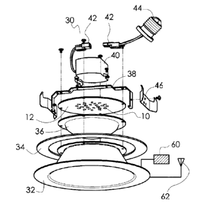
big box retailers, and in many other applications like an RV, custom homes,
etc. Such lighting
fixtures are generally referred to herein as "recessed."
SUMMARY OF THE INVENTION
[005] The present invention in various preferred embodiments is directed to
an LED light
fixture for installation to a building framework, comprising a plurality of
LEDs, a printed circuit
board preferably a Metal Core Printed Circuit Board (MCPCB), wherein the LEDs
are mounted
toward the center of the printed circuit board, and the LEDs are connected by
paths of electrical and
thermal conductor material. The printed circuit board has an annular surface
area around the outer
periphery or edge optionally containing the electrical and thermal conductor
material and no LEDs.
Thc fixture includes a reflector trim having an open top, wherein the printed
circuit board is
mountcd to the open top and part of the annular surface area coupled to or in
close proximity to the
reflector trim, wherein the reflector trim includes a material with a thermal
conductivity of 2 Wim-
K through 49 W/m-K inclusive, and includes a minimum reflectivity of 20%. The
reflector trim
includes an annular flange around the open top to engage the printed circuit
board at the annular
surface area. The printed circuit board may have an oversized outside diameter
so that it overhangs
the top of the reflector trim. The fixture further includes an LED driver for
powering the LEDs, a
mounting system spacing the LED driver away from the printed circuit board
creating a gap
therebetween, and attachment means for mounting the light fixture to an
enclosure, can, pan, or
building framework.
- 2 -
CA 02880397 2015-01-29
BRIEF DESCRIPTION OF THE DRAWINGS
[006] FIGS. 1(a)-1(e) show a first embodiment of the present invention
recessed LED light
fixture, including a top plan view, a perspective view, a side elevational
view, a cross-sectional
view A-A, and an exploded view. This embodiment includes a quick connect
terminal adapted to
connect to an optional Edison screw plug. Friction blades are mounted to
opposite sides of the
driver mounting bracket and used to install the light fixture inside a can,
housing, or like enclosure.
[007] FIGS. 2(a)-2(e) show a second embodiment, which is the first
embodiment light fixture
of FIG. 1 but with V-torsion spring clips instead of the friction blades.
[008] FIGS. 3(a)-3(d) are several views of the cone-shaped reflector trim
used in the light
fixtures of FIGS. 1 and 2.
[009] FIGS. 4(a)-4(d) are several views of the optional domed lens or light
diffuser from
FIGS. 1 and 2. The lens may be transparent, translucent, textured, and/or
include surface contours
for decoration and for refracting light in a desired pattern.
[010] FIGS. 5(a)-(d) are views of the printed circuit board used in the
light fixtures of FIGS. 1
and 2, including an array of LEDs arranged according to a preferred embodiment
of the present
invention.
[011] FIGS. 6(a)-6(d) are several views of the LED driver mounting bracket.
[012] FIGS. 7(a)-7(c) are several views of the V-torsion spring clip used
to mount the light
fixture inside of a standard housing, can, or enclosure.
[013] FIGS. 8(a)-(e) are several views of the friction blade.
[014] FIGS. 9(a) and 9(b) are two views of a gasket optionally fitted to
the flange lip around
the reflector trim shown in drawing FIG. 2. The gasket helps thermally
insulate and isolate the
living area beneath the ceiling from the space above the ceiling.
10151 FIGS. 10(a)-10(e) show a third embodiment of the present invention
recessed LED light
fixture, including a top plan view, a perspective view, a side elevational
view, a cross-sectional
view B-B, and an exploded view. This embodiment includes a fixed, standard
Edison screw plug at
the top to engage a preexisting Edison socket for retrofitting an existing
recessed light fixture.
-3 -
CA 02880397 2015-01-29
Friction blades are mounted to opposite sides of the driver mounting bracket
and used to install the
light fixture inside a pre-existing housing, can, pan, or enclosure.
[016] FIGS. 11(a)-11(e) show a fourth embodiment, which is the third
embodiment of FIG. 10
but using V-torsion spring clips instead of the friction blades.
[017] FIG. 12 contains several views of the cone-shaped reflector trim used
in the FIGS. 10
and 11 embodiments.
[018] FIG. 13 contains several views of the optional domed lens or light
diffuser used in the
FIGS. 10 and 11 embodiments. The lens may be transparent, translucent,
textured, and/or includes
surface contours.
[019] FIG. 14 contains several views of the printed circuit board used in
the FIGS. 10 and 11
embodiments, including an array of LEDs arranged according to the present
invention.
[020] FIG. 15 includes several views of the LED driver mounting bracket
used on the FIGS.
and 11 embodiments.
[021] FIG. 16 includes several views of the V-torsion spring clip.
[022] FIG. 17 includes several views of the friction blade.
[023] FIG. 18 includes two views of a gasket.
[024] FIG. 19 is a plan view of a preferred embodiment printed circuit
board (PCB) showing
an arrangement of LEDs positioned on the PCB with copper electrical conductor
paths and pie-
slice-shaped copper sections for heat dissipation.
[025] FIGS. 20(a) and 20(b) are a cross-sectional view and an enlarged top
plan view,
respectively, of a portion of a PCB showing the different laminated layers of
materials.
[026] FIG. 21 is a schematic side elevational view and shows the attachment
of an LED die to
the PCB substrate.
DETAILED DESCRIPTION OF THE PREFERRED EMBODIMENTS
[027] As is known in the art, heat is the number one enemy of the LED as it
reduces operating
life of the LED, diminishes lumens output, wastes energy in that the energy
consumed is not
- 4 -
CA 02880397 2015-01-29
efficiently converted to visible light due to heat buildup. Indeed, thermal
mitigation is a primary
concern to maintain LED lifetime duty ratings and maintain the stated lumens
output. Thermal
mitigation becomes even more important when the LED assembly is mounted in an
enclosed
fixture, space, or housing. Exacerbating the heat buildup scenario, if that
assembly is located in a
ceiling plenum, the ambient temperaturcs can become elevated further dropping
the temperature
gradient between the LED assembly and the ambient air.
[028] With further advancements in LED technology, power density is now
spread across
multiple LED emitters, reducing the need for bulky heat sinks made to handle
high density power
requirements. Heat sink size has dropped, and often is the same element used
as the housing for the
LED assembly. Conventional LED heat sinks can range from spun metal cylinders
to die cast
aluminum truncated cone structures with radial cooling fins. In conventional
LED light fixtures,
these types of bulky, metal, finned heat sinks are needed to cool the printed
circuit board used for
mounting the LEDs and sometimes the LED driver.
[029] The printed circuit board (PCB) is the first conductive element with
which the hot LEDs
come in contact. With the present invention preferred embodiments shown in the
attached drawing
figures, the printed circuit board is now the primary thermal conductive
element needed inside a
recessed housing or enclosure -- a secondary heat sink with its bulk, fins,
and weight, is
unnecessary.
[030] As seen in drawing FIGS. 5 and 14, spreading the LEDs 10 across the
printed circuit
board 12 provides an electrical and/or thermal path for the LEDs 10. The
printed circuit board 12
provides a path for heat transfer from the LED 10 to the ambient air
surrounding the printed circuit
board 12. Specifically, by enlarging the LEDs 10 and clustering the LEDs 10
generally toward the
center 14 of the PCB 12, the heat will naturally flow to the outer edges 16 of
the PCB 12, both on
the unfinished side (FIG. 5(d)) of the board 12 and on the printed side (FIG.
5(b)) of the board 12.
Using multiple LEDs 10 in close proximity in a cluster near the center 14 of
the PCB 12 creates a
temperature differential of approximately 5 degrees Celsius between the LEDs
in the center and the
LEDs at the edge of the LED array, shown in FIG. 5(b). This is based on
empirical observations of
recessed LED lighting fixtures in sizes and wattages typically intended for
residential or home use.
- 5 -
CA 02880397 2015-01-29
[031] To further improve cooling, optionally placing each LED 10 on the
printed circuit board
12 with its own section of copper or like electrical conductor material that
extends from the LED to
the outer perimeter of the PCB 12 further helps to reduce the temperature
differential between the
center LEDs and the LEDs at the perimeter or outer circumference of the LED
array. A preferred
embodiment of this arrangement is depicted in drawing FIG. 19, where the
electrical conductor
paths or leads appear as straight, radial paths at the periphery of the PCB 12
and serpentine paths
interconnecting the LEDs 10 within the LED array.
[032] In particular, FIG. 19 is a schematic, top plan view of the LEDs,
copper or like electrical
conductor leads, and copper or like electrical conductor sections arranged on
the PCB shown in
drawing FIGS. 5 and 14. On the PCB, the small rectangles represent LEDs 10
that are located on
narrow paths made of copper, and these paths provide the electrical conduction
to power the LEDs.
The narrow copper electrical conductor paths are insulated from one another;
there are also large,
pie slice sections made from copper and they serve as the thermal conductors
to radiate heat off the
PCB. It is preferable that the copper electrical conductor paths are
separate/discrete/insulated from
the thermal paths. Some LEDs do not have an isolated area under the LED array
for thermal
conduction, and in those instances, the thermal paths and electrical paths are
shared. Other shapes
for the serpentine electrical conductor paths and thermal paths and sections
are contemplated. For
example, the electrical conductor paths may be straight and arranged like
spokes on a wheel, and
the large thermal sections may bc ovals, polygons, semicircles, etc., or any
combination thereof.
[033] In sum, if the printed circuit board is maximized for thermal
conduction, it may include
sections of copper, separated electrically from the other LEDs, for each LED
placed on the circuit
board. This copper section(s) would be designed to run from the center of the
printed circuit board
out to the edge of the printed circuit board to carry the thermal energy to
the cooler edges of the
board where the convective air flow is created. This pattern would be similar
to the spread of a
peacock's feathers, where they all start at a common center and each feather
tapers larger as it
extends from the center.
- 6 -
[034] Further, the copper sections supporting each LED may supply
electrical current to the
LEDs and/or function as thermal dissipation away from the LEDs. The copper
sections occupy
large open surface areas to help with heat dissipation.
[035] Drawing FIG. 20(a) is a side elevational view, in cross-section, of a
portion of the
preferred embodiment PCB 12. FIG. 20(b) is an enlarged, top plan view of the
cross-section from
FIG. 20(a). The PCB 12 is preferably made from a Metal Core Printed Circuit
Board (MCPCB),
and the copper paths and sections 18 from drawing FIG. 19 are laminated to the
dielectric polymer
layer 19. The MCPCB is preferably made from a base material 21 such as
aluminum, copper, or
similar type metal, or any combination thereof. This metallic base 21 material
has high thermal
conductivity that helps with heat dissipation away from the circuit board 12.
In drawing FIG. 20(a),
a circuit foil layer 18 contains the copper paths and sections 12 for
electrical conduction and/or heat
dissipation, and a layer 17 is a protective soldermask layer. Drawing FIG. 21
is a schematic
showing the LED die 10 attached to the MCPCB substrate 12. The LED die 10 is
attached to the
MCPCB 12 using preferably a layer of thermal conductive paste, adhesive, or
solder 20 known in
the art. An optional translucent or transparent dome 22 may cover and protect
the LED die 10. An
optional via is shown in FIG. 20(a) to facilitate mounting a LED die. In a
preferred embodiment,
the primary cooling mechanism is the metal base or core 21 of the MCPCB 12
that radiates and
conducts heat away from the LED die 10.
[036] With the PCB arrangement depicted in the top plan view of FIG. 19,
thermal dissipation
from the PCB is greater in the Z direction (perpendicular, out of the page),
top to bottom, than in the
x-y direction along the surface of the PCB. The preferred embodiment PCB thus
maximizes
thermal conduction of heat at the board level by including additional PCB
surface area at the
periphery extending well past the LED array, and that extended diameter of the
PCB helps to
conduct heat to the coolest portion of the PCB (i.e., the outer periphery or
diameter) and ultimately
to the fixture housing. That is, the coolest air within the light fixture
enclosure is near the side walls
of the housing or can, so directing the heat toward the outer perimeter via a
PCB that is larger in
diameter promotes convective cooling and increases the surface area for
convective heat transfer.
When the preferred embodiment PCB is placed into the enclosure, housing, or
can, the enclosure
- 7 -
CA 2830397 2017-06-02
CA 02880397 2015-01-29
allows for convection within itself. When this enclosure has a temperature
differential between the
top and bottom of the enclosure, convective air flow is possible, and if the
enclosure has thermally
conductive sides, the heated air that rises is cooled by the thermally
conductive walls of the
enclosure.
[037] The LED assembly on a PCB can be insulated from making contact with
all thermally
conductive elements within the recessed enclosure and maintain safe operating
temperatures,
provided that there is sufficient surface for the printed circuit board and
provided that the ambient
temperature within the enclosure stays below a predetermined value.
[038] Drawing FIGS. 5, 14 and 19 show preferred embodiment printed circuit
boards to which
the LEDs are mounted. As described above, the LEDs 10 are arrayed but
concentrated at the center
of the PCB disk 12, and the PCB disk has a larger surface area than needed to
support the LEDs.
This enlarged surface area helps with heat dissipation.
[039] Further, the cluster of LEDs 10 are preferably concentrated toward
the center and are not
mounted at the outer periphery proximate the circumference of the PCB 12,
leaving large, open
surface areas. The large open surface areas of the PCB are laminated or
covered with thermal
conductive material known in the art to help radiate and conduct heat as
described above.
Moreover, the large open areas of the PCB 12 can be mated to the upper lip 48
of the cone-shaped
reflector trim 32. Direct contact allows for thermal conduction between the
PCB 12 and the
reflector trim 32, thus using the mass of the reflector trim 32 for heat
dissipation, radiation, and
convection into the surrounding environment. Thermal conduction between the
reflector trim 32
and the PCB 12 enhances life of the LED, but the reflector trim does not need
to be made from
traditional, thermally conductive elements such as aluminum or copper. The
reflector trim 32 can
be made from a material with a thermal conductivity of about 2 W/m-K to about
49 W/m-K,
inclusive of the upper and lower limits, and preferably has a minimum light
reflectivity coating of
about 20% for use in a recessed LED light fixture of a standard size and
wattage for residential or
commercial use. From empirical observations, such a range ensure proper
cooling for long duty life
of the LEDs and electrical components. Materials for the reflector trim 32
include thin sheets of
steel, iron, or thermally conductive plastic, formed into a cone, with its
interior covered by a
- 8 -
CA 02880397 2015-01-29
reflective layer. In an alternative embodiment, the reflector trim 32 can be
made from a material
with a thermal conductivity as small as about 0.2 W/m-K, found in, for
example, low thermal
conductivity plastic.
[040] In an alternative embodiment, there is a minimum of about a 3 mm
annular gap between
the PCB 12 and reflector trim 32, and/or the same annular gap between the
diffuser 36 and the
reflector trim 32. These gaps enable convective air flow for additional
cooling.
[041] The preferred embodiment PCB 12 is mounted in a light fixture shown
in FIGS. 1 and
11. The FIG. 1 LED light fixture has a quick connect that optionally fits to
[a] an Edison plug, or
[b] a current day junction box quick connect. The FIG. 11 embodiment simply
has an Edison plug
that screws into the existing Edison socket of a conventional recessed
lighting fixture using standard
incandescent bulbs, halogen bulbs, or CFL compact fluorescent bulb and would
replace these light
sources.
[042] FIG. 1(c) is an exploded view of a preferred embodiment LED recessed
light fixture 30,
for fitment in a standard recessed light fixture can, enclosure, housing, or
like building or dwelling
framework. The building or dwelling framework is a residential home or
commercial building
having a ceiling space, a drop down ceiling, wall space, lamp post, floor
lamp, or any kind of
construction space or support for mounting a light fixture. Thc LED light
fixture 30 includes a
preferably cone-shaped reflector trim 32, an optional insulating gasket 34, a
domed diffuer/lens 36,
all of which are held together by a bracket 38.
[043] The reflector trim 32 is preferably made in a light reflective color
or painted or coated
with such color to direct the LED light downward toward the living space
below. The reflector trim
has a circular shaped top. and as seen in FIGS. 1(b) and 1(e), has a diameter
that is smaller than the
outside diameter of the PCB 12. Indeed, the outer periphery of the PCB 12
overhangs the reflector
trim 32 beneath it. The PCB 12 thus has an oversized diameter and its
associated surface area is
likewise enlarged; this helps achieve better radiation and convective cooling
of the LEDs 10
mounted thereto.
[044] Mounted underneath the bracket 38 is the PCB 12 with its downward
facing LED array
10. There can be a single LED or a plurality of LEDs preferably arranged in a
cluster. The LED or
- 9 -
CA 02880397 2015-01-29
LEDs may be packaged into a plastic housing with electrical connections, or
may be a simple LED
die.
[045] Placed atop the bracket 38 is the LED driver 40 with its electrical
connection, and in this
embodiment, terminating in a quick connect 42. The complementary half of the
quick connect 42 is
connected to an Edison plug 44. Optional attachment means in the form of
friction blades 46 are
affixed to the bracket 38. The friction blades 46 are compliant and push
against the inside of the
pre-existing can, pan, housing, enclosure or building framework (not shown) to
stabilize and hold
the light fixture 10 therein.
[046] In various alternative embodiments, as seen in FIG. 1(c), the light
fixture 30 may include
a receiving/sending module 60 mounted on the fixture for communication with a
wireless control
for remote control of the fixture. The antenna 62 for the wireless interface
is integral with the
reflector trim 32. Electronics for such wireless remote controls are well
known in the art as a means
for wirelessly controlling the light fixture, such as from a smartphone or
remote control, especially
for controlling ceiling fans, for example. The receiving/sending module may
transmit a signal for
Near Field Communication (NFC) to transfer information between devices when
they are in
contact.
[047] FIG. 11(c) is an exploded view of another preferred embodiment LED
recessed light
fixture 31 with a fixed Edison plug, for fitment in a standard recessed light
fixture can. The fixture
31 includes a reflector cone 32, an optional insulating gasket 34, a dome
shaped diffuser or lens 36,
all of which are held together by a bracket 50. Mounted underneath the bracket
50 is the PCB 12
with its downward facing LED array 10. Also attached to the bracket 50 is the
LED driver 40
electrically wired to an Edison plug 44. Optional attachment means in the form
of V-torsion spring
clips 52 are affixed on opposite sides of the bracket 50. The biased legs of
the V-torsion spring
clips 52 can be finger pinched against the bias and passed through slots in
the can, pan, or fixture
enclosure, where they pop open to hold and support the weight of the entire
assembly 31 in place
inside the can. Other attachment means arc contemplated, including twist
locks, screws, bolts,
springs with hooked ends, flip locks, latches, etc.
- 10-
CA 02880397 2015-01-29
[048] As seen in drawing FIGS. 1(d) and 11(d), there is an optional space
above the PCB 12
created by the shaped of the mounting bracket 38, 50. The LED driver 40 with
its electronics and
power supply attaches to the driver mounting bracket 38, 50 and is thus
preferably spaced apart
from the hot PCB/LEDs 12, 10. This is best seen in the cross-sectional views A-
A and B-B of
FIGS. 1 and 11, respectively.
[049] Further, in FIGS. 1(b) and 11(b), it can be seen that the entire top
side of the PCB 12 is
exposed to the ambient environment, because no portion is covered by the LED
driver 40 by having
it mounted directly to the PCB 12. This allows great surface area of the hot
PCB 12 to radiate heat
into the environment along with cooling from convection currents of the
surrounding air.
[050] Indeed, this optional gap enables thermal convection that helps cool
the LEDs 10 and the
PCB 12. In addition, the driver bracket 38, 50 itself may act as a thermal
conductor and heat
dissipater. In conventional recessed LED light fixtures, this space between
the driver and the PCB
is normally occupied by a large, finned, metal heat sink, which is missing
here. The present
invention thus does not require this bulky secondary (or tertiary, etc.) heat
sink to operate efficiently
within its design parameters. The bulk, weight, material, manufacturing, labor
costs, etc. associated
with the secondary heat sink are thus eliminated by the present invention
design.
[051] Another embodiment includes a medium based screw-in Edison or like
adaptor to allow
the assembly to be electrically connected to a light fixture containing a
medium base lamp holder,
lamp post or similar type socket.
[052] As seen in the FIGS. 1-18, the preferred embodiments provide an LED
assembly
consisting of a printed circuit board, LEDs, a lens for optical uniformity
(not required but helpful)
and a reflector cone (may be made from thermally insulating materials or
thermally conductive
materials) for shielding the LEDs from occupants in the room and distributing
the light within the
needed space, and brackets which hold an LED driver and the means to mount the
assembly within
an enclosure. The lens, in this assembly, has also been used to thermally
isolate the printed circuit
board assembly from the reflector cone. If the lens were not present, a spacer
may be used to
maintain this spacing. The present invention light fixture is different
because it does not require
contact with the ambient environment of the room below the enclosure or
require a secondary heat
- 11 -
CA 02880397 2015-01-29
sink to manage the thermal characteristics of the LED assembly. All
conventional assemblies of
this nature have required an additional heat sink coupled to the LED assembly
to maintain the
thermal stability of their designs.
[053] In an alternative embodiment, the LEDs are directly bonded to the PCB
substrate
without the traditional thermoplastic housing, wire bonds, and reflow process.
[054] A further alternative embodiment combines the LED driver components
directly on the
printed circuit board, around the perimeter with selective areas for the
driver components. This
embodiment eliminates the external driver and reduces the number of components
needed for the
final assembly and the overall height. Such a compact fixture is versatile in
that it can be mounted
inside a tight ceiling space or for retrofitting a conventional recessed light
fixture that has a small
can, for example.
[055] The cnd benefits to the consumer are lower costs, better shielding
angles, because the
LED assembly can be taller since the large, secondary heat sink has been
eliminated. Further, a
more durable and light efficient reflector cone can be selected because
material choices are now
more flexible to deliver the best mechanical features rather than focusing on
thermal conductivity of
such components.
[056] While particular forms of the invention have been illustrated and
described, it will be
apparent that various modifications can be made without departing from the
scope of thc invention.
It is contemplated that components from one embodimcnt may be combined with
components from
another embodiment.
- 12 -