Note: Descriptions are shown in the official language in which they were submitted.
CA 02880515 2015-01-29
WO 2014/022082
PCT/US2013/050487
RESIDUE HYDROCRACKING
FIELD OF THE DISCLOSURE
[0001] Embodiments disclosed herein relate generally to processes for
hydrocracking
residue and other heavy hydrocarbon fractions. More specifically, embodiments
disclosed herein relate to processes for cracking residue and other heavy
hydrocarbon
fractions while simultaneously reducing asphaltenic sediment foimation
downstream
of ebullated bed reactor systems and improving the quality of the conversion
products.
BACKGROUND
[0002] Attempts to mitigate sediment deposition problems in equipment
downstream
of ebullated bed reactors, such as separators, exchangers, heaters, and
fractionation
equipment have used various chemical and mechanical means. However, sediment
deposition remains a challenge. Precipitation of asphaltenic material
("sediment") is a
major issue in most, if not all, high conversion residue hydrocracking units,
especially
those utilizing ebullated bed hydrocracking, and often limits the extent of
conversion
and reduces the on stream factor of many units. Additionally, products from
ebullated
bed hydrocracking are typically of lower quality, as a significant portion of
the
conversion occurs as a result of thermal cracking and a contribution of
catalytic
hydroconversion that improves product quality is somewhat limited.
SUMMARY OF THE CLAIMED EMBODIMENTS
[0003] In one aspect, embodiments disclosed herein relate to a process for
upgrading
residuum hydrocarbons and decreasing tendency of the resulting products toward
asphaltenic sediment formation in downstream processes. The process may
include:
contacting a residuum hydrocarbon fraction and hydrogen with a hydroconversion
catalyst in a hydrocracking reaction zone to convert at least a portion of the
residuum
hydrocarbon fraction to lighter hydrocarbons; recovering an effluent from the
hydrocracking reaction zone; contacting hydrogen and at least a portion of the
effluent
with a resid hydrotreating catalyst; and separating the effluent to recover
two or more
hydrocarbon fractions.
[0004] In another aspect, embodiments disclosed herein relate to a system
for
upgrading residuum hydrocarbons and decreasing tendency of the resulting
products
CA 02880515 2015-01-29
WO 2014/022082
PCT/US2013/050487
toward asphaltenic sediment formation in downstream processes. The system may
include: a hydrocracking reaction zone for contacting a residuum hydrocarbon
fraction and hydrogen with a hydroconversion catalyst to convert at least a
portion of
the residuum hydrocarbon fraction to lighter hydrocarbons and recovering a
hydrocracked effluent; a reactor for contacting hydrogen and at least a
portion of the
hydrocracked effluent with a resid hydrotreating catalyst; and a separation
system for
separating the effluent to recover two or more hydrocarbon fractions.
[0005] In another aspect, embodiments disclosed herein relate to a process
for
upgrading residuum hydrocarbons and decreasing tendency of the resulting
products
toward asphaltenic sediment formation in downstream processes. The process may
include: contacting a residuum hydrocarbon fraction and hydrogen with a first
hydroconversion catalyst in a first hydrocracking reaction zone to convert at
least a
portion of the residuum hydrocarbon fraction to lighter hydrocarbons and
recover a
first hydrocracked effluent; quenching the first hydrocracked effluent with at
least one
of an aromatic diluent and a hydrogen-containing gas stream; separating the
quenched
first hydrocracked effluent to recover a first overheads vapor fraction
comprising
distillate hydrocarbons and a first bottoms liquid fraction; contacting
hydrogen and
the first bottoms liquid fraction with a second hydroconversion catalyst,
which may
be the same or different than the first hydroconversion catalyst, in a second
hydrocracking reaction zone to convert at least a portion of the first bottoms
liquid
fraction to lighter hydrocarbons and recover a second hydrocracked effluent;
contacting hydrogen and at least a portion of the second hydrocracked effluent
with a
first resid hydrotreating catalyst to form a hydrotreated product; separating
the
hydrotreated product to recover two or more hydrocarbon fractions.
[0006] Other aspects and advantages will be apparent from the following
description
and the appended claims.
BRIEF DESCRIPTION OF DRAWINGS
[0007] Figure 1 is a simplified process flow diagram of a process for
upgrading
residuum hydrocarbon feedstocks according to embodiments disclosed herein.
[0008] Figure 2A is a simplified process flow diagram of a process for
upgrading
residuum hydrocarbon feedstocks according to embodiments disclosed herein.
2
CA 02880515 2015-01-29
WO 2014/022082
PCT/US2013/050487
[0009]
Figure 2B is a simplified process flow diagram of a process for upgrading
residuum hydrocarbon feedstocks according to embodiments disclosed herein.
[0010] Figure 3 is a simplified process flow diagram of a process for
upgrading
residuum hydrocarbon feedstocks according to embodiments disclosed herein.
[0011] Figure 4 is a simplified process flow diagram of a process for
upgrading
residuum hydrocarbon feedstocks according to embodiments disclosed herein.
[0012] Figure 5 is a simplified process flow diagram of a process for
upgrading
residuum hydrocarbon feedstocks according to embodiments disclosed herein.
[0013] Figure 6 is a simplified process flow diagram of a process for
upgrading
residuum hydrocarbon feedstocks according to embodiments disclosed herein.
DETAILED DESCRIPTION
[0014] In
one aspect, embodiments herein relate generally to hydroconversion
processes, including processes for hydrocracking residue and other heavy
hydrocarbon fractions. More specifically, embodiments disclosed herein relate
to
hydroconversion processes for treating residue and other heavy hydrocarbon
fractions
while simultaneously reducing asphaltenic sediment formation downstream of
ebullated bed reactor systems and improving the quality of the conversion
products.
[0015] Hydroconversion processes disclosed herein may be used for
reacting
residuum hydrocarbon feedstocks at conditions of elevated temperatures and
pressures in the presence of hydrogen and one or more hydroconversion catalyst
to
convert the feedstock to lower molecular weight products with reduced
contaminant
(such as sulfur and/or nitrogen) levels. Hydroconversion processes may
include, for
example, hydrogenation, desulfurization, denitrogenation, cracking,
conversion, and
removal of metals, Conradson Carbon or asphaltenes, etc.
[0016] As used herein, residuum hydrocarbon fractions are defined as a
hydrocarbon fraction having boiling points or a boiling range above about 343
C but
could also include whole heavy crude processing. Residuum hydrocarbon
feedstocks
that may be used with processes disclosed herein may include various refinery
and
other hydrocarbon streams such as petroleum atmospheric or vacuum residue,
deasphalted oil, deasphalter pitch, hydrocracked atmospheric tower or vacuum
tower
bottom, straight run vacuum gas oil, hydrocracked vacuum gas oil, fluid
catalytically
cracked (FCC) slurry oils, vacuum gas oil from an ebullated bed process, as
well as
3
CA 02880515 2015-01-29
WO 2014/022082
PCT/US2013/050487
other similar hydrocarbon streams, or a combination of these, each of which
may be
straight run, process derived, hydrocracked, partially desulfurized, and/or
low-metal
streams.
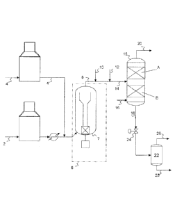
[0017] Referring now to Figure 1, a residuum hydrocarbon fraction
(residue) 2 is
heated and mixed with a hydrogen rich treat gas 4 and fed to a hydrocracking
stage 6.
Hydrocracking stage 6 may include a single ebullated bed reactor 7, as
illustrated, or
may include multiple reactors arranged in parallel and/or series. In ebullated
bed
reactor(s) 7, the residuum hydrocarbon fraction may be hydrocracked under
hydrogen
partial pressures of 70 to 170 bara, temperatures of 380 C to 450 C, and a
LHSV of
0.15 to 2.0
111 in the presence of a hydroconversion catalyst.
[0018] Within the ebullated bed reactor 7, the catalyst is back-mixed
and
maintained in random motion by the recirculation of liquid product. This is
accomplished by first separating the recirculated oil from the gaseous
products. The
oil is then recirculated by means of an external pump or a pump having an
impeller
mounted in the bottom head of the reactor.
[0019] Target residue conversion in the first hydrocracking stage may
typically be
in the range from about 30 wt% to about 75 wt%, depending upon the feedstock
being
processed. However, conversion should be maintained below the level where
sediment formation becomes excessive. In addition to converting the residue,
it is
anticipated that sulfur removal will be in the range from about 40% to about
80%,
metals removal will be in the range from about 40% to about 85%, and Conradson
Carbon Removal (CCR) will be in the range from about 40% to about 65% in the
first
hydrocracking stage 6.
[0020] Liquid and vapor effluent from the first hydrocracking stage 6
may be
recovered via flow line 8 and quenched with an aromatic solvent 10 and or a
hydrogen-containing gas stream 12. Aromatic solvent 10 may include any
aromatic
solvent, such as slurry oil from a Fluid Catalytic Cracking (FCC) process or
sour
vacuum residue, among others.
[0021] The quenched effluent 14 is then fed to a countercurrent reactor
/ stripper
15 loaded with hydroprocessing (hydrotreating) catalyst(s). The heavy liquid
from
the first stage reactor effluent traverses downward within the reactor /
stripper 15,
4
CA 02880515 2015-01-29
WO 2014/022082
PCT/US2013/050487
passes through the lower catalyst zone B, containing a residue hydrotreating
catalyst,
and comes into contact with hydrogen, fed via flow line 16, travelling in a
countercurrent manner up the reactor / stripper. Additional
hydrodemetallization
(HDM), hydrodesulfurization (HDS), Conradson Carbon Reduction (HDCCR),
hydrodearomatization (HDA), and other reactions occur in catalyst zone B,
resulting
in a bottoms fraction 18 more amenable to downstream processing. Catalyst zone
B
may include a packed catalyst bed, impregnated structured packing, and other
forms
typical for containing catalyst within a catalytic distillation reactor
system.
[0022] The light distillates in the vapor phase entering the reactor /
stripper 15
traverse upward within the reactor stripper 15, passing through upper catalyst
zone A,
contacting hydrogen travelling in a co-current manner up the reactor stripper.
The
catalyst in catalyst zone A may include a distillate hydrotreating catalyst,
and may
provide incremental HDS, HDN and HDA capability, further improving the quality
of
the light distillates recovered. The vapor fraction, light distillates and
unreacted
hydrogen, may be recovered from reactor / stripper 15 via flow line 20 and
routed
through a gas cooling, purification, and recycle gas compression system (not
shown).
Alternatively, the vapor fraction 20 may be first processed through an
integrated
hydroprocessing reactor system (not shown), alone or in combination with
external
distillates and/or distillates generated in the hydrocracking process, and,
thereafter,
routed to the gas cooling, purification, and compression system (not shown).
[0023] Bottoms fraction 18 recovered from reactor / stripper 15 may
then be
flashed in flash vessel 22, where the pressure of the fluid may be decreased
across
control valve 24, for example, before entering the flash vessel. This flashing
results
in a vapor fraction 26, with may be routed to an atmospheric distillation
system after
cooling along with other distillate products recovered from the gas cooling
and
purification system. The liquid fraction 28 may be further stripped to recover
additional atmospheric distillates, producing a stripped heavy unconverted oil
product
similar to an atmospheric tower bottoms product, having a boiling point in the
range
from about 343 C to about 427 C, which may then be sent to a vacuum
distillation
system to recover vacuum distillates.
[0024] Referring now to Figures 2A and 2B, where like numerals
represent like
parts, as an alternative to reactor / stripper 15, the liquid and vapor
effluent 8 from the
CA 02880515 2015-01-29
WO 2014/022082
PCT/US2013/050487
first hydro cracking stage 6 may be quenched using an aromatic solvent and/or
hydrogen and fed to an upflow reactor or OCR (on-line catalyst replacement)
reactor
30 having a catalyst zone C containing a residue hydroprocessing catalyst,
providing
additional HDM, HDS, HDCCR, and HDA, among other reactions, improving the
quality of the effluent. As compared with an upflow reactor the application of
an OCR
reactor permits catalyst to be added and withdrawn on-stream in a similar
manner to
that routinely practiced in ebullated bed hydrocracking reactors. In this way
reactor
volume can be reduced and constant product quality can be maintained over the
course of the operation without necessitating the shutdown of the unit to
replace the
catalyst inventory.
[0025] In some embodiments, such as illustrated in Figure 2A, the
effluent from
upflow reactor 30 may be fed via flow line 32 to a vapor / liquid separator
34, which
may optionally contain a packing zone 36 where it is contacted with hydrogen
rich
gas 37. Light distillates may be recovered from vapor / liquid separator 34
via flow
line 38 and routed through a gas cooling, purification, and recycle gas
compression
system (not shown), as described above. Alternatively, the vapor fraction 38
may be
first processed through an integrated hydroprocessing reactor system (not
shown),
alone or in combination with external distillates and/or distillates generated
in the
hydrocracking process, and, thereafter, routed to the gas cooling,
purification, and
compression system (not shown). Heavy distillates may be recovered from vapor
/
liquid separator 34 via flow line 40 and processed as described with respect
to flash
vessel 22 for Figure 1.
[0026] In other embodiments, such as illustrated in Figure 2B, the
effluent from
upflow or OCR reactor 30 may be fed via flow line 42 to a reactor / stripper
15,
including an upper catalyst zone A and a lower catalyst zone B, as described
above
with respect to Figure 1.
[0027] As noted above, hydroprocessing systems according to embodiments
disclosed herein may include one or more hydrocracking stages. Referring now
to
Figure 3, one embodiment of a hydroprocessing process according to embodiments
herein is illustrated, including an intermediate vapor / liquid separator and
a reactor /
stripper following the last hydrocracking stage.
6
CA 02880515 2015-01-29
WO 2014/022082
PCT/US2013/050487
[0028] A residuum hydrocarbon fraction (residue) 52 is heated and mixed
with a
hydrogen rich treat gas 54 and fed to a hydrocracking stage 56. Hydrocracking
stage
56 may include a single ebullated bed reactor 57, as illustrated, or may
include
multiple reactors arranged in parallel and/or series. In ebullated bed
reactor(s) 57, the
residuum hydrocarbon fraction may be hydrocracked under hydrogen partial
pressures
of 70 to 170 bara, temperatures of 380 C to 450 C, and a LHSV of 0.25 to 2.0 h-
1 in
the presence of a hydroconversion catalyst.
[0029] Within the ebullated bed reactor 57, the catalyst is back-mixed
and
maintained in random motion by the recirculation of liquid product. This is
accomplished by first separating the recirculated oil from the gaseous
products. The
oil is then recirculated by means of an external pump or a pump having an
impeller
mounted in the bottom head of the reactor.
[0030] Target residue conversion in the first hydrocracking stage may
typically be
in the range from about 30 wt% to about 75 wt%, depending upon the feedstock
being
processed. However, conversion should be maintained below the level where
sediment formation becomes excessive. In addition to converting the residue,
it is
anticipated that sulfur removal will be in the range from about 40% to about
75%,
metals removal will be in the range from about 40% to about 80%, and Conradson
Carbon Removal (CCR) will be in the range from about 40% to about 60% in the
first
hydrocracking stage 56.
[0031] Liquid and vapor effluent from the first hydrocracking stage 56
may be
recovered via flow line 58 and quenched with an aromatic solvent 60 or
hydrogen rich
gas 62. Aromatic solvent 60 may include any aromatic solvent, such as slurry
oil
from a Fluid Catalytic Cracking (FCC) process or sour vacuum residue, among
others.
[0032] The quenched effluent 64 is then fed to an intermediate vapor /
liquid
separator 66, which may optionally contain a packing section 68, where the
intermediate heavy unconverted liquid is further contacted with hydrogen rich
gas 73.
The heavy liquid from the first hydrocracking stage effluent may then be
recovered as
a bottoms fraction 70 from vapor liquid separator 66, combined with hydrogen
71,
and fed to a second hydrocracking stage 72, which may include one or more
ebullated
bed reactors 74, where systems with multiple reactors may include parallel
and/or
series arrangements. Ebullated bed reactors 74 may operate in a similar manner
as
7
CA 02880515 2015-01-29
WO 2014/022082
PCT/US2013/050487
described above, providing incremental conversion of the heavy liquids to
vacuum
gas oils and other light products.
[0033] Target residue conversion exiting the second hydrocracking stage
may
typically be in the range from about 50 wt% to about 85 wt%, depending upon
the
feedstock being processed. However, conversion should be maintained below the
level where sediment formation becomes excessive. In addition to converting
the
residue, it is anticipated that overall sulfur removal exiting the second
hydrocracking
stage 72 will be in the range from about 60% to about 85%, metals removal will
be in
the range from about 60% to about 92%, and Conradson Carbon Removal (CCR) will
be in the range from about 50% to about 75%.
[0034] Vapor product 76 recovered from vapor / liquid separator 66 may
be
quenched with an aromatic solvent and/or hydrogen rich gas 78 and combined
with
the vapor and liquid effluent 80 recovered from the last hydrocracking stage
(or last
ebullated bed reactor within a hydrocracking stage). The combined quenched
products may be fed via flow line 82 to a reactor / stripper 85 intermediate
an upper
catalyst zone A and a lower catalyst zone B.
[0035] The heavy liquid in the combined quenched stream 82 traverses
downward
within the reactor / stripper 85, passes through the lower catalyst zone B,
containing a
residue hydrotreating catalyst, and comes into contact with hydrogen, fed via
flow
line 86, travelling in a countercurrent manner up the reactor / stripper.
Additional
hydrodemetallization (HDM), hydrodesulfurization (HDS), Conradson Carbon
Reduction (HDCCR), hydrodearomatization (HDA), and other reactions occur in
the
fixed catalyst zone B, resulting in a bottoms fraction 88 more amenable to
downstream processing. Catalyst zone B may include a packed catalyst bed,
impregnated structured packing, and other forms typical for containing
catalyst within
a catalytic distillation reactor system.
[0036] The light distillates in the vapor phase entering the reactor /
stripper 85
traverse upward within the reactor stripper 85, passing through upper catalyst
zone A,
contacting hydrogen travelling in a co-current manner up the reactor stripper.
Catalyst zone A may include a distillate hydrotreating catalyst, and may
provide
incremental HDS, HDN and HDA capability, further improving the quality of the
light distillates recovered. The vapor fraction, light distillates and
unreacted
8
CA 02880515 2015-01-29
WO 2014/022082
PCT/US2013/050487
hydrogen, may be recovered from reactor / stripper 85 via flow line 90 and
routed
through a gas cooling, purification, and recycle gas compression system (not
shown).
Alternatively, the vapor fraction 90 may be first processed through an
integrated
hydroprocessing reactor system (not shown), alone or in combination with
external
distillates and/or distillates generated in the hydrocracking process, and,
thereafter,
routed to the gas cooling, purification, and compression system (not shown).
[0037] Bottoms fraction 88 recovered from reactor / stripper 85 may
then be
flashed in flash vessel 92, where the pressure of the fluid may be decreased
across
control valve 94, for example, before entering the flash vessel. This flashing
results
in a vapor fraction 96 which may be routed to an atmospheric distillation
system after
cooling along with other distillate products recovered from the gas cooling
and
purification system. The liquid fraction 98 may be further stripped to recover
additional atmospheric distillates, producing a stripped heavy unconverted oil
product, similar to an atmospheric tower bottoms product, having a boiling
point in
the range from about 343 C to about 427 C, which may then be sent to a vacuum
distillation system to recover vacuum distillates.
[0038] In an alternative embodiment, the vapor and liquid effluent 80,
with or
without the vapor fraction 76, may be processed using an upflow or OCR reactor
(not
illustrated) and separated similar to the embodiments described with respect
to
Figures 2A and 2B. The additional conversion and enhanced HDA, HDM, HDCCR,
and HDS achieved using the upflow reactor (with catalyst zone C) and/or the
reactor /
stripper (with catalyst zones A and B) following the last hydrocracking stage
provides
significant benefits over mere separation of the combined hydrocracking stage
effluents, improving the quality of the resulting products and making the
resulting
products more amenable to downstream processing.
[0039] In addition to the benefits that may be received using the
upflow or
distillation reactor systems following the last hydrocracking stage, further
benefits
may be realized by use of upflow and/or distillation reactor systems
intermediate the
first and second (and/or between subsequent) hydrocracking stages, as
illustrated in
Figures 4-6, where like numerals represent like parts.
[0040] Referring now to Figure 4, as opposed to separating vapor
products from
the liquid products in first hydrocracking stage 56 effluent 58 via an
intermediate
9
CA 02880515 2015-01-29
WO 2014/022082
PCT/US2013/050487
vapor / liquid separator 66, the first hydrocracking stage 56 effluent 58 may
be fed to
a reactor / stripper 102 containing an upper catalyst zone A and a lower
catalyst zone
B. Hydrogen may be introduced to reactor / stripper 102 via flow line 104, for
example. The liquid and vapor effluent from the first hydrocracking stage
effluent 58
may be quenched using an aromatic solvent and/or quench gas 60 and fed to a
counter-current reactor / stripper containing hydroprocessing catalyst(s). The
heavy
liquid from the from the first stage reactor effluent traverses downward
within the
reactor / stripper 102, passes through the lower catalyst zone B, containing a
residue
hydrotreating catalyst, and comes into contact with hydrogen, fed via flow
line 104,
travelling in a countercurrent manner up the reactor / stripper. Additional
hydrodemetallization (HDM), hydrodesulfurization (HDS), Conradson Carbon
Reduction (HDCCR), hydrodearomatization (HDA), and other reactions occur in
the
catalyst zone B. A bottoms fraction 108 may be recovered from the reactor /
stripper
102, combined with hydrogen 110, and fed to the second hydrocracking stage 72
for
further processing as described above.
[0041] The light distillates in the vapor phase entering the reactor /
stripper 102
traverse upward within the reactor / stripper 102, passing through upper
catalyst zone
A, contacting hydrogen travelling in a co-current manner up the reactor /
stripper.
Catalyst zone A may include a distillate hydrotreating catalyst, and may
provide
incremental HDS, HDN and HDA capability, further improving the quality of the
light distillates recovered. The vapor fraction 112, light distillates and
unreacted
hydrogen recovered from reactor / stripper 102, may be further processed in
reactor /
stripper 85 along with the second hydrocracking stage effluent or fed to the
common
gas cooling, purification, and recycle gas processing system as described
above.
[0042] Similarly, the first hydrocracking stage effluent may be
quenched and fed
to an upflow or OCR reactor 120, as illustrated in Figure 5, contacting the
hydrocracking effluent 58 with a hydroprocessing catalyst in catalyst zone C
to result
in additional conversion, HDM, HDS, HDCCR, and/or HDA. The effluent 122 may
then be fed to an intermediate vapor / liquid separator 66 and processed as
described
above with respect to the respective portions of Figure 3. The second
hydrocracking
stage effluent 80 and the vapor recovered from intermediate vapor / liquid
separator
may then be processed as described above with respect to the respective
portions of
CA 02880515 2015-01-29
WO 2014/022082
PCT/US2013/050487
any one of Figures 1, 2A (as illustrated in Figure 5), 2B, and 3, where
additional
processing of the vapor recovered from vapor / liquid separator 66, if
desired, may be
accomplished by feeding a portion or all of the vapor fraction 122 to the
downstream
upflow or OCR reactor and/or reactor / stripper.
[0043] As a further alternative, processing of the intermediate
effluent recovered
from the first hydrocracking stage may be performed as illustrated in Figure
6. In this
embodiment, the first hydrocracking stage effluent may be quenched with an
aromatic
solvent and/or hydrogen gas and fed to an upflow or OCR reactor 130. The
effluent
132 may be fed directly to second hydrocracking stage 72 via flow line 134, or
may
be fed via flow line 136 to reactor / stripper 138 containing an upper
catalyst zone A
and a lower catalyst zone B, for treatment and separation similar to that
described
above with respect to reactor / stripper 102 (Figure 4). The vapor fraction
140, light
distillates and unreacted hydrogen recovered from reactor / stripper 138, and
the
second hydrocracking stage effluent 80 may then be processed as described
above
with respect to any one of Figures 1, 2A, 2B (as illustrated in Figure 6), and
3, where
additional processing of the vapor recovered from vapor / liquid separator
138, if
desired, may be accomplished by feeding a portion or all of the vapor fraction
140 to
the downstream upflow or OCR reactor and/or reactor / stripper.
[0044] Hydroconversion catalysts that may be used in catalyst zones A,
B, and C
include catalyst that may be used for the hydrotreating or hydrocracking of a
hydrocarbon feedstock. A hydrotreating catalyst, for example, may include any
catalyst composition that may be used to catalyze the hydrogenation of
hydrocarbon
feedstocks to increase its hydrogen content and/or remove heteroatom
contaminants.
A hydrocracking catalyst, for example, may include any catalyst composition
that
may be used to catalyze the addition of hydrogen to large or complex
hydrocarbon
molecules as well as the cracking of the molecules to obtain smaller, lower
molecular
weight molecules.
[0045] Hydroconversion catalyst compositions for use in the
hydroconversion
process according to embodiments disclosed herein are well known to those
skilled in
the art and several are commercially available from W.R. Grace & Co.,
Criterion
Catalysts & Technologies, and Albemarle, among others. Suitable
hydroconversion
catalysts may include one or more elements selected from Groups 4-12 of the
Periodic
11
CA 02880515 2015-01-29
WO 2014/022082
PCT/US2013/050487
Table of the Elements. In some embodiments, hydroconversion catalysts
according to
embodiments disclosed herein may comprise, consist of, or consist essentially
of one
or more of nickel, cobalt, tungsten, molybdenum and combinations thereof,
either
unsupported or supported on a porous substrate such as silica, alumina,
titania, or
combinations thereof As supplied from a manufacturer or as resulting from a
regeneration process, the hydroconversion catalysts may be in the form of
metal
oxides, for example. In some embodiments, the hydroconversion catalysts may be
pre-sulfided and/or pre-conditioned prior to introduction to the hydrocracking
reactor(s).
[0046] Distillate hydrotreating catalyst that may be useful in catalyst
zone A may
include catalyst selected from those elements known to provide catalytic
hydrogenation activity. At least one metal component selected from Group 8-10
elements and/or from Group 6 elements is generally chosen. Group 6 elements
may
include chromium, molybdenum and tungsten. Group 8-10 elements may include
iron, cobalt, nickel, ruthenium, rhodium, palladium, osmium, iridium and
platinum.
The amount(s) of hydrogenation component(s) in the catalyst suitably range
from
about 0.5% to about 10% by weight of Group 8-10 metal component(s) and from
about 5% to about 25% by weight of Group 6 metal component(s), calculated as
metal
oxide(s) per 100 parts by weight of total catalyst, where the percentages by
weight are
based on the weight of the catalyst before sulfiding. The hydrogenation
components
in the catalyst may be in the oxidic and/or the sulphidic form. If a
combination of at
least a Group 6 and a Group 8 metal component is present as (mixed) oxides, it
will
be subjected to a sulfiding treatment prior to proper use in hydrocracking. In
some
embodiments, the catalyst comprises one or more components of nickel and/or
cobalt
and one or more components of molybdenum and/or tungsten or one or more
components of platinum and/or palladium. Catalysts containing nickel and
molybdenum, nickel and tungsten, platinum and/or palladium are useful.
[0047] Residue hydrotreating catalyst that may be useful in catalyst zone
B may
include catalysts generally composed of a hydrogenation component, selected
from
Group 6 elements (such as molybdenum and/or tungsten) and Group 8-10 elements
(such as cobalt and/or nickel), or a mixture thereof, which may be supported
on an
alumina support. Phosphorous (Group 15) oxide is optionally present as an
active
12
CA 02880515 2016-06-14
ingredient. A typical catalyst may contain from 3 to 35 wt % hydrogenation
components, with an alumina binder. The catalyst pellets may range in size
from 1/32
. inch to 1/8 inch, and may be of a spherical, extruded, trilobate or
quadrilobate shape.
In some embodiments, the feed passing through the catalyst zone contacts first
a
catalyst preselected for metals removal, though some sulfur, nitrogen and
aromatic
removal may also occur. Subsequent catalyst layers may be used for sulfur and
nitrogen removal, though they would also be expected to catalyze the removal
of
metals and/or cracking reactions. Catalyst layer(s) for demetallization, when
present.
may comprise catalyst(s) having an average pore size ranging from 125 to 225
Angstroms and a pore volume ranging from 0.5-1.1 cm31g. Catalyst layer(s) for
denitrificationidesulfurization may comprise catalyst(s) having an average
pore size
ranging from 100 to 190 Angstroms with a pore volume of 0.5-1.1 ctnitg. U.S.
Pat.
No. 4,990,243 describes a hydrotreating catalyst having a pore size of at
least about
60 Angstroms, and preferably from about 75 Angstroms to about 120 Angstroms. A
demetallation catalyst useful for the present process is described, for
example, in U.S.
Pat. No. 4,976,848.
Likewise. catalysts useltil for desulfurization of heavy streams are
described, for example, in U.S. Pat. Nos. 5.215,955 and 5,177,047.
Catalysts
useful for desulfurization of middle distillate, vacuum gas oil streams and
naphtha
streams are described, for example, in U.S. Pat. No. 4,990,243.
100481 Residue
hydrotreating catalyst useful in catalyst zone C may include catalysts
comprising a porous refractory base made up of alumina, silica, phosphorous,
or
various combinations of these. One or more types of catalysts may be used as
residue
hydrotreating catalyst C, and where two or more catalysts are used, the
catalysts may
be present in the reactor zone as layers. The catalysts in the lower layer(s)
may have
good demetallation activity. The catalysts may also have hydrogenation and
desulfurization activity, and it may be advantageous to use large pore size
catalysts to
maximize the removal of metals. Catalysts having these characteristics are not
optimal
fbr the removal of carbon residue and sulfur. The average pore size for
catalyst in the
lower layer or layers will usually be at least 60 Angstroms and in many eases
will be
13
CA 02880515 2015-01-29
WO 2014/022082 PCT/US2013/050487
considerably larger. The catalyst may contain a metal or combination of metals
such
as nickel, molybdenum, or cobalt. Catalysts useful in the lower layer or
layers are
described in U.S. Pat. Nos. 5,071,805 5,215,955, and 5,472,928. For example,
those
catalysts as described in U.S. Patent No. 5,472,928 and having at least 20% of
the
pores in the range of 130 to 170 Angstroms, based on the nitrogen method, may
be
useful in the lower catalysts layer(s). The catalysts present in the upper
layer or layers
of the catalyst zone should have greater hydrogenation activity as compared to
catalysts in the lower layer or layers. Consequently catalysts useful in the
upper layer
or layers may be characterized by smaller pore sizes and greater carbon
residue
removal, denitrification and desulfurization activity. Typically, the
catalysts will
contain metals such as, for example, nickel, tungsten, and molybdenum to
enhance the
hydrogenation activity. For example, those catalysts as described in U.S.
Patent No.
5,472,928 and having at least 30% of the pores in the range of 95 to 135
Angstroms,
based on the nitrogen method, may be useful in the upper catalysts layers. The
catalysts may be shaped catalysts or spherical catalysts. In addition, dense,
less friable
catalysts may be used in the upflow fixed catalyst zones to minimize breakage
of the
catalyst particles and the entrainment of particulates in the product
recovered from the
reactor.
[0049] One skilled in the art will recognize that the various catalyst
layers may not be
made up of only a single catalyst, but may be composed of an intermixture of
different catalysts to achieve the optimal level of metals or carbon residue
removal
and desulfurization for that layer. Although some hydrogenation will occur in
the
lower portion of the zone, the removal of carbon residue, nitrogen, and sulfur
may
take place primarily in the upper layer or layers. Obviously additional metals
removal
also will take place. The specific catalyst or catalyst mixture selected for
each layer,
the number of layers in the zone, the proportional volume in the bed of each
layer, and
the specific hydrotreating conditions selected will depend on the feedstock
being
processed by the unit, the desired product to be recovered, as well as
commercial
considerations such as cost of the catalyst. All of these parameters are
within the skill
of a person engaged in the petroleum processing industry and should not need
further
elaboration here.
[0050] EXAMPLES
14
CA 02880515 2015-01-29
WO 2014/022082
PCT/US2013/050487
[0051] Example I
[0052] A first theoretical example is described with reference to Figure 1
illustrating
the effect the addition of a reactor/stripper has on the heavy unconverted oil
and
distillate product qualities. Specifically in this example the ebullated bed
hydrocracking stage operates at a liquid hourly space velocity of 0.25 hr-1
and a
temperature between 425 C and 432 C, converting between 65 to 73% of the
vacuum
residue fraction in the feed. In addition approximately 75% of sulfur, 80% of
the
metals, 60% of the CCR and 65% of the asphaltenes in the residue feed is
removed in
this hydrocracking stage.
[0053] The resulting heavy unconverted oil product after quenching then
flows
downward through the residue hydrotreating catalyst bed where it contacts
hydrogen
flowing upward and countercurrent to the unconverted oil which undergoes
further
reaction. In this bed the unconverted residue fraction undergoes further
desulfurization, demetallation and Conradson Carbon Reduction and asphaltene
conversion reactions. In addition any remaining free radicals formed as a
result of the
thermal cracking occurring in the upstream hydrocracking stage are saturated
reducing coke precursor and sediment formation, thereby improving the
stability of
the resultant unconverted oil product.
[0054] In particular it is envisaged that the residue hydrotreatment
reaction bed will
operate at a LHSV of between 4 to 8 hr-1 and a WABT (i.e., weighted average
bed
temperature) of 380 C to 400 C with a gas flow ranging between 70 to 100
Nm3/m3
of feed. As a result it is estimated sulfur, CCR and metals removal will all
increase by
1 to 2%. More importantly, however, sediment formation will be suppressed by
15 to
20%.
[0055] The light distillates in the vapor phase entering the
reactor/stripper along with
lighter distillate fractions stripped from the unconverted oil in the residue
hydrotreatment reaction bed flow up through the distillate hydrotreatment bed
along
with hydrogen contained in the effluent from the hydrocracking reaction stage
plus
excess hydrogen exiting the top of the residue hydrotreatment bed. It is
estimated that
about 50% of the distillate formed in the hydrocracking reaction stage will be
in the
vapor phase flow to the distillate hydrotreatment bed. This will contain the
vast
majority of the naphtha boiling range material, between 50 to 60% of the
diesel
CA 02880515 2015-01-29
WO 2014/022082
PCT/US2013/050487
boiling range material and about 25 to 30% of the vacuum gasoil fraction. In
particular it is envisaged that the distillate hydrotreatment bed will operate
at a LHSV
ranging from 1.6 to 2.5 hr-1 and a WABT ranging from 360 C to 390 C. At these
operating conditions HDS and HDN removals will exceed 99%, producing a naphtha
fraction with < lwppm sulfur and nitrogen and an ultra low sulfur diesel
product with
<10 wppm sulfur.
[0056] Example 2
[0057] A second theoretical example is described with reference to Figure
2B
illustrating the combined effect the addition of an upflow or OCR reactor and
subsequent reactor/stripper has on residue conversion, reaction yields and
heavy
unconverted oil and distillate product qualities. As in Example 1, it is
envisaged that
the ebullated bed hydrocracking stage operates at a LHSV of 0.25 hr-1 and a
temperature of 425 C to 432 C, converting between 65 and 73 of the vacuum
residue
fraction in the feed. In addition, as in Example 1 approximately 75% of the
sulfur,
80% of the metals, 60% of the CCR and 65% of the asphaltenes in the residue
feed is
removed in the hydrocracking stage.
[0058] In Example 2, the liquid and vapor effluent from the hydrocracking
reaction
stage after being quenched is further processed in an upflow reactor,
containing
residue hydroprocessing catalyst, thereby providing for additional sulfur,
metals, CCR
and asphaltene removal. It is envisaged that the upflow reactor will operate
at a LHSV
of 1.0 to 2.0 hr-1 and a temperature between 380 C to 400 C. At these
conditions the
vacuum residue conversion will increase by an additional 1 to 2%. In addition
to the
increased residue conversion, HDS removals will increase from 3.5 to 5.5%, CCR
and
asphaltene removals will increase 4 to 7%, and metals removals will increase
from 5
to 7%. As a result of the increased CCR and asphaltene conversion and the
inhibition
of coke precursor formation, the sediment content of the unconverted oil is
expected
to decline by as much as 50% significantly improving the stability of the
unconverted
oil product.
[0059] As in Example 1, the resultant heavy unconverted oil and light
distillates
undergo further treatment in a reactor/ stripper at similar conditions and
with similar
product quality improvements as outlined previously. In summary, therefore, as
a
result of adding an upflow or OCR reactor and a reactor/stripper overall
conversion
16
CA 02880515 2015-01-29
WO 2014/022082
PCT/US2013/050487
and removals and product qualities are expected to increase as defined in the
table
below:
Ebullated Bed Resid Upflow/OCR Reactor +
Parameter Hydrocracking Stage Reactor/Stripper
LHSV, hr-1
EB Hydrocracking Stage 0.25
Upflow/OCR Reactor 1.0-2.0
Reactor/Stripper
Lower Bed 4-8
Upper Bed 1.6-2.5
Temperature, C
EB Hydrocracking Stage 425-432
Upflow/OCR Reactor 380-400
Reactor/Stripper
Lower Bed 380-400
Upper Bed 360-390
HDS Removal, wt% 75 79.5-82.5
CCR Removal, wt% 60 65-69
HDM Removal, wt% 80 85-87
Asphaltene Removal, wt% 65 70-74
Heavy Unconverted Oil X <0.5X
Sediments (SHFT), wt%
Naphtha Product
Nitrogen, wppm <1
Sulfur, wppm <1
Diesel Product Sulfur, wppm < 10
[0060] As described above, use of a reactor / stripper and/or an upflow
reactor may
provide for an enhanced degree of conversion, HDS, HDA, HDM, and HDCCR. This
may improve the quality of the hydrocarbon product and reduce the tendency of
the
product for asphaltenic sediment formation in downstream equipment.
[0061] Although the processes described above include one or two
hydrocracking
stages, embodiments including more than two stages are contemplated herein.
Further, embodiments disclosed herein illustrate multi-stage processing of the
resid
feeds with and without use of an interstage vapor-liquid separation (via a
vapor /
liquid separator or a reactor / stripper). While enhanced conversion and
improved
product quality may be realized using these intermediate steps, the additional
conversion, HDS, HDA, HDM, and HDCCR realized using the upflow reactor and/or
17
CA 02880515 2015-01-29
WO 2014/022082
PCT/US2013/050487
reactor / stripper following the last hydrocracking stage may sufficiently
reduce the
tendency of asphaltenic sedimentation in downstream equipment.
[0062] Advantageously, embodiments disclosed herein integrate fixed bed
and
ebullated bed hydroprocessing technologies, utilizing different catalyst
systems for
the ebullated bed and fixed bed reaction stages to produce a better quality
product
from residue hydrocracking. The additional interstage and/or terminal stage
processing using upflow reactors and/or reactor / strippers may extend residue
conversion limits, typically 55% to 75%, up to about 90% or greater. Further,
such
processing may allow the first ebullated bed hydrocracking stage (and
additional
stages) to be operated at high temperature and high space velocity. Such
processing
may simultaneously (or sequentially) strip the ebullated bed reactor liquid
product
while further stabilizing the product via additional conversion of
asphaltenes.
Further, such processing may reduce unit investment by integrating ebullated
and
fixed bed hydroprocessing into a common gas cooling, purification, and
compression
loop. The improved products and decreased sedimentation may provide for
reduced
cleaning frequencies (lower operating costs and extended run lengths).
[0063] Processes disclosed herein may additionally be readily
integrated into existing
designs. For example, an intermediate or terminal vapor-liquid separator may
be
converted to a reactor / stripper via modification of the vessel internals. As
another
example, an upflow reactor may be readily inserted between an ebullated bed
hydrocracking stage and an intermediate or terminal vapor-liquid separator.
[0064] While the disclosure includes a limited number of embodiments,
those skilled
in the art, having benefit of this disclosure, will appreciate that other
embodiments
may be devised which do not depart from the scope of the present disclosure.
Accordingly, the scope should be limited only by the attached claims.
18