Note: Descriptions are shown in the official language in which they were submitted.
Method for processing steel slag and hydraulic mineral binder
The invention relates to a method for processing steel slag to produce a
hydraulic mineral binder with a high hardening potential and to recover iron
and a hydraulic mineral binder
Steel slag, which is also called LD slag, LDS, LD converter slag , BOS or
SWS, may - according to the process - still contain very large quantities of
iron. This iron is present partly in metallic form but mainly in the form of
oxides
minerally bonded in the slag. These iron oxides present in the slag cannot be
recovered in a purely mechanical way, as they are fixedly incorporated in the
slag matrix and must initially be transformed into the elementary metallic
form
through a thermo-chemical reduction. The slag matrix consists mainly of the
typical oxides calcium oxide, silicon dioxide and aluminium oxide. In contrast
with other slag forms, such as for example blast furnace slag, however, they
do not arise in hydraulically active phases and are not therefore suited for
high-quality utilisation in cement. They are therefore used almost exclusively
as grit in highway construction.
EP 1 370 501 81 discloses for example a method for treating steel slag in
order to provide the slag with the properties of a hydraulic binder. The
resulting product is described as at least equivalent to Portland cement
clinker. In this case, the steel slag ¨ which contains, relative to the slag
total
weight, at least 45 wt. % of calcium oxide and less than 30 wt. % of Fe2O3 ¨
undergoes oxidising treatment with oxygen or air at a pressure ranging
between 1 and 15 bars, at a temperature ranging between 1650 C to 1400 C.
A lime source is added to this slag and supplemented if required with a
silicon
dioxide source or an aluminium oxide source. The proportions of the lime
source and optionally the silicon dioxide or aluminium oxide source are
selected so that the slag, after transformation and at room temperature, has a
Fe2O3 content of at least 13 wt. % and a mineralogical composition
comprising at least 40 wt. % of the mineralogical phase C3S and more than 10
wt. % of calcium chloride / fluoride in the form of the mineralogical phases
C2F
or C4AF.
1
CA 2880664 2019-02-19
A disadvantage of this method is that the iron present in the slag is not
recovered.
Another method for processing steel slag is described in EP 1 697 271 B1. In
this case, a hydraulic binder is to be produced having at least 25 wt. `)/0 of
calcium and magnesium aluminosilicates, at least 5 wt. % of mineral oxides
and / or halides as well as maximum 31 wt. % of aluminium oxide, maximum
wt. % of calcium aluminoferrite and maximum 0.01 wt. % of carbon. In
order to obtain this product, base materials - including also steel slag - are
to
be melted in corresponding quantities in a reducing atmosphere. The resulting
product is to be isolated. This can be carried out by means of rapid cooling,
for example with water or air, and also by means of slow cooling.
Irrespectively of the type of cooling, it seems that no noteworthy quantities
of
the main clinker phase alite are formed. It is not described whether and how
any elementary iron hereby formed is separated.
It is thus the object of the invention to indicate a method for processing
steel
slag, wherein both a hydrauk mineral binder with a high hardening potential
can be produced and also iron can be recovered. It is further an object of the
invention to provide a hydraulic mineral binder with a hign hardening
potential.
This object is achieved according to the invention through a method for
processing steel slag and through a
hydraulic
mineral binder
Advantageous embodiments of the invention are indicated in the sub-claims
and in the description.
In the method according to the invention there is firstly provision for a feed
product comprising steel slag with iron compounds, in particular in oxide
form,
and MnO, whereby the MnO may be contained in the steel slag. This feed
product is further processed as melt by incorporating reducing agent into the
CA 2880664 2019-02-19
CA 02880664 2015-01-30
English translation of PCT/EP2012/00374 as filed
melt to reduce the iron compounds in order to achieve a lime saturation factor
of between 90 and 110 in the mineral melt portion, wherein the reducing agent
is introduced in a non-oxidising atmosphere. Subsequently the melt is cooled
in a defined way with the melt solidifying in 15 minutes at the earliest.
Elementary iron is then mechanically separated from the solidified melt. The
solidified melt, which has a reduced iron content, is then supplied for use as
a
hydraulic mineral binder.
According to the meaning of the invention, feed product is intended to mean
the steel slag and, if necessary, further correcting components such as MnO.
Sufficient MnO may hereby already be present in the slag, meaning that no
correcting components need to be added. This is the case at least with some
steel slags examined. In most cases the iron compounds are present in the
steel slag as iron halides, iron sulphides, iron selenides and in particular
iron
oxides such as FeO, Fe2O3 or Fe304.
The feed product can be heated in suitable receptacles to the melt or it can
also be provided externally in the melt¨liquid state. An electric arc furnace,
in
particular in a three-phase closed form, may be used for example to melt the
feed product or to further heat the melt.
By introducing the reducing agent, the iron compounds are transformed into
the elementary metallic form. In the mineral melt part, a lime saturation
factor
in a range of between 90 and 110, preferably between 95 and 105, is
achieved. Mineral melt part can be understood as the melt less the
elementary iron. The lime saturation factor (LSF, Kalkstandard or KSt)
indicates the CaO content actually present in the raw material or clinker as a
percentage of the respective CaO content which can be bonded under large-
scale combustion and cooling conditions in the maximum case to SiO2, A1203
and Fe2O3.
It is defined by the following equation:
3
CA 02880664 2015-01-30
English translation of PCT/EP2012100374 as filed
KS = 100 ' Ca)
t
2,80 .37.02 + 1,1 AI ni n 7 PP n 2- 3 ¨p. ¨2 ¨3
(where KSt lime saturation factor).
By carrying out the reduction in a non-oxidising atmosphere, this prevents
back-oxidation of the iron which has already been reduced and thus increases
the yield of elementary iron. This further contributes to achieving the lime
saturation factor.
After the melt has solidified the elementary iron can be mechanically
separated and supplied for a further utilisation. A large proportion of the
iron
settles in the lower region of the melt vessel due to the greater density
relative
to the remainder of the slag. A further portion remains in the form of
droplets
and inclusions in the cooled slag.
The slag with the reduced iron content can be used as hydraulic mineral
binder. This binder is described below as LDS binder.
The method according to the invention allows, in a simple and efficient
manner, a high proportion of elementary iron to be recovered from steel slag
and furthermore an extremely reactive hydraulic mineral binder to be obtained
which is predominantly suited as composite material for high-quality binder.
This LDS binder is characterised by very high reactivity and hardening
capacity. It has an alite content (C3S) of at least 40 wt. A.
The invention is based essentially upon three interacting basic ideas:
firstly,
the provision of MnO in the melt; secondly, the reduction of the iron until
the
indicated lime saturation factor is reached in the mineral melt part; and,
thirdly, the slow defined cooling.
The defined cooling process causes the formation of very large alite crystals.
These can be up to a millimetre in size. Furthermore no back-formation
4
CA 02880664 2015-01-30
English translation of PCT/EP2012/00374 as filed
processes to belite (C2S) and free or unslaked lime (CaO) can be seen at the
edges of the crystals during investigations. Slow cooling processes lead,
under conventional clinker production conditions, to breakdown of the alite
into belite and free lime. Against this background, a high-resource clinker
cooling is necessary within the cement production.
The particularly high reactivity of the elite phase obtained in spite of the
large
crystals is due to the presence of Mn2'. ions, which are incorporated into the
lattice structure of the alite phase and disturb this, with the result that
the
hardening potential of the LDS binder - due in particular to the elite phase -
is
considerably increased.
In the inventive processing of the melt under reducing conditions the Mn is
present in its bivalent form as Mn2+. Introduction into the lattice of the
elite is
thus possible, whereby Ca is replaced in the lattice. Incorporation rates of
up
to 3% are hereby achieved.
This is not possible in conventional cement clinker production. Insofar as Mn
compounds are present in the cement raw materials, the Mn will be present
through the oxidative process in the cement clinker production as Mn3+. in
this
way the Mn3+ tends to be incorporated onto the lattice sites of the Fe in the
C4AF. An incorporation of Mn3+ onto the Ca lattice sites of the alite or the
belite is not possible.
Consequently, a comparable reactivity increase of the alite is not possible in
conventional cement clinker production in an oxidising atmosphere, as the
manganese, if present, is present as Mn3+. The same also applies to all
methods for treating steel slag which are carried out under oxidising
conditions.
The high stability of the alite can be due on the one hand to the fact that
the
formation of the alite in the LDS binder, in contrast with the conventional
sintering process, in the cement clinker production, takes place slowly from
CA 02880664 2015-01-30
English translation of PCTIEP2012/00374 as filed
= the melt phase according to the invention. On the other hand the
stability is
due to the incorporation of Mn24
.
Finally, the required lime saturation factor also plays a decisive role in the
high alite proportion and the high reactivity of the LDS binder according to
the
invention.
In principle, any amount of MnO may be present in the feed product. It is
advantageous, however, if the feed product has 0.1 wt. % to 10 wt. %, in
particular 0.5 wt. A to 5 wt. %, of MnO. Al this content level of manganese
oxide it is guaranteed that a significant quantity of Mn2t ions will be
incorporated into the crystal lattice of the elite phase and thereby disturb
the
crystal structure.
It is advantageous if the feed product contains up to 5 wt. % of A1203 and /
or
30 to 50 wt. % of CaO and / or 10 to 20 wt. A of SiO2. It is even more
advantageous if the feed product contains 3 to 5 wt. % of Al2O3 and / or 35 to
45 wt. % of CaO and / or 15 to 20 wt. % of SiO2.
With these phase compositions the formation of the alite phase is enhanced
having regard to thermo-chemical viewpoints. Furthermore, in these
concentration ranges of the oxides in question, it is highly probable that a
lime
saturation factor of between 90 and 110, or even more preferably, between 95
and 105, will be achieved. Should the aforementioned composition not
already be contained in the steel slag material supplied, the oxides lacking
can optionally be added before or during the melt process.
The melt advantageously has a temperature of approximately 1600 C to
approximately 1800 C, in particular from 1650 C to 1750 C, before and / or
during the reduction. All components of the feed product, in particular the
oxide portions, are completely melted in this temperature range and the
reduction reaction takes place sufficiently quickly so that a rapid
progression
of the reduction process is guaranteed from energy and thermo-chemical
viewpoints.
6
CA 02880664 2015-01-30
English translation of PCTIEP2012100374 as filed
The non-oxidising atmosphere can be a reducing atmosphere. The reduction
process, which takes place mainly through the added reducing agent in solid
form, is thereby further supported.
It is preferable for carbon, silicon and / or other metals or semi-metals to
be
used as reducing agents. In particular petroleum coke is suited for carbon
modification as it has a very high specific surface and correspondingly high
reactivity. Silicon, calcium and aluminium have the further advantage that the
oxides can form parts of the slag.
At least a part of the reducing agent can be blown into the melt, for example
by means of an inert gas flow. Hollow electrodes are suited in particular for
blowing the reducing agent into the melt when using an electric arc furnace.
Besides a particularly efficient distribution of the reducing agent in the
melt, a
further contribution to mixing is achieved by the blowing-in. The use of an
inert
gas ensures that undesirable secondary reactions, in particular oxidation of
the reducing agent and the oxide components contained in the melt, are
avoided. Argon, for example, is particularly suited for use as an inert gas. A
different proportion of the reducing agent can optionally be previously mixed
with the feed slag in a certain ratio.
When using carbon as a reducing agent, carbon monoxide and carbon
dioxide can be produced as by-products of the reduction of the oxides. These
gases escape from the melt and this can lead to foaming of the melt. In order
to reduce foaming, it may be advantageous to incorporate borax into the melt.
According to a preferred embodiment of the method according to the
invention, liquid elementary iron is separated after the reducing process and
before the solidifying process of the melt. As liquid elementary iron has a
higher density than the melt phase, it collects at the bottom of the melt
furnace and can be removed from there relatively simply. Melt furnace or
melting unit can be understood within the scope of the invention to mean a
receptacle for receiving the melt phase, which allows the melt to be kept in
the
7
CA 02880664 2015-01-30
English translation of PCT/EP2012/00374 as filed
liquid state through additional energy input, for example an electric arc
furnace.
In principle the melt can be cooled slowly as desired. It is preferable,
however,
if the melt has solidified at the latest after four hours, in particular two
hours.
Within this time period, thermodynamically stable mineralogical phases, in
particular of alite, can form.
The defined cooling can be carried out in cooling receptacles. In particular,
ingot or permanent moulds or other receptacles are suitable for this purpose,
with which the cooling process can be influenced in terms of time. The cooling
receptacles can be supplied by special casting machines, which are in turn
filled from the melting unit.
According to a preferred embodiment of the method according to the invention
the mechanical separation of the elementary iron takes place by means of a
grinding process and a classifying process. For this method step, a method is
suited in particular, as disclosed in the international patent application WO
2011/107124 Al. The iron is released during the grinding process and then
separated on a grinding plate through the density differences between the iron
and the mineralogical matrix. It is subsequently discharged over the plate
edge and further enriched optionally through subsequent sorting and
classification processes. in order to reduce and de-agglomerate the solidified
melt, a roller mill, preferably of the LOESCHE type, is used.
In addition the invention relates to a hydraulic mineral binder which has a
mineralogical composition of at least 40 wt. % of alite (C3S) and a lime
saturation factor of approximately 90 to 110. A higher elite content of 50 wt.
/0, in particular 60 wt. %, is preferable. The hydraulic mineral binder can be
produced by means of the method according to the invention and is also
described within the scope of the invention as LDS binder.
The LDS binder has a mineralogical composition of maximum 30 wt. % of
glass phases. These do not make any contribution to the binding ability of the
8
CA 02880664 2015-01-30
English translation of PCREP2012/00374 as filed
binder but can bind free lime, i.e. calcium oxide, and thereby increase the
lime
saturation factor.
The invention will be explained in greater detail below with the aid of a
schematic exemplary embodiment by reference to the figures, in which:
Fig. 1 shows a schematic flowchart of an embodiment of the method
according to the invention; and
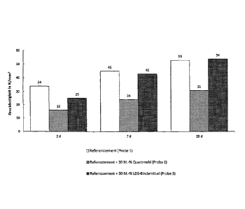
Fig. 2 shows a bar chart revealing investigations into the strength of the
hydraulic mineral binder according to the invention.
A feed product is provided in step I in the flowchart according to Fig. 1.
This
feed product comprises essentially LD slag. The feed product has a MnO
content in the range of between 1 wt. % and 5 wt. %. Many LD slags, which
are also described as SWS, already have a MnO content in the desired range.
If this is not the case, the Mno is added to the slag. Reducing agent can
already be added to the feed product in this step. Petroleum coke is
particularly suitable for this purpose.
In the subsequent step II, the processing of the feed product to the melt
takes
place, if required. The slag can either be obtained already in the melt liquid
state from an upstream process or also be present in the cold solid form.
Melting and / or heating of the slag can take place in an electric arc
furnace. It
can be operated in resistance operation with a fire-resistant composition of
graphite or carbon-containing fire-resistant material. The electric arc
furnace
can also be described as a melt unit.
The melt should reach a temperature of between approximately 1650 C and
1750 C before the addition of reducing agent is started in step III.
By reducing the iron compounds in the melt, carbon monoxide and / or carbon
dioxide can be produced which escape from the melt as gases. This can lead
9
CA 02880664 2015-01-30
English translation of PCT/EP2012/00374 as filed
to foaming of the melt. In order to reduce foaming, a small quantity of borax
can be added to the melt. The viscosity of the melt is hereby reduced.
In order to suppress the re-oxidation of the reduced iron, the furnace
atmosphere is enriched with an inert gas, for example with argon. The argon
can also be directly introduced into the melt. A part of the reducing agent
can
then also be blown with the argon flow directly into the melt. The argon
flowing through the melt causes swirling of the melt bath and this has a
positive effect on the metal separation.
As soon as essentially all the iron compounds present in the feed product
have been reduced, the remaining mineral melt part should have a lime
saturation factor of between 90 and 110. This is to be noted with the
composition of the feed product. The desired lime saturation factor can be
achieved with many LD slags.
In step IV, the liquid melt is conveyed, for example via a pouring apparatus,
into special cooling units such as ingot moulds and slowly cooled there in a
time period of at least fifteen minutes to approximately two hours. A part of
the
iron ¨ approximately 80% - is deposited both in the melt unit and in the
cooling units as a separate phase at the bottom. It can be separated here
still
in the liquid state. Another portion of the metal phase remains, however,
after
cooling, in the form of drops and inclusions in the mineral part. In this
case,
mechanical processing thereof is necessary to increase the metal yield.
This mechanical separation of elementary iron takes place in stage V through
a grinding process by means of a LOESCHE roller mill and subsequent
classifying. In this case the iron can be separated due to the difference in
density from the mineralogical part. The method described in WO
2011/107124 Al is particularly suited for this purpose.
The remaining mineral part is the LDS binder according to the invention,
which is present in stage VI. It can be utilised as a high-quality hydraulic
mineral binder.
CA 02880664 2015-01-30
English translation of PCT/EP2012/00374 as filed
Table 1 lists the chemical composition of a feed product which is an untreated
LE) slag and the LDS binder obtained by means of the method according to
the invention. The values are given here in wt. % in each case.
Base slag (untreated) LDS binder
SiO2 13.9 19.6
A1203 1.7 2.7
Fe2O3 - - 28.8 2.7
CaO 42.7 62.3
MgO 3.3 3.4
TiO2 0.47 0.72
MnO 5.2 3.89
K20 0 0.04
-1\1a20 0.02 0.29
SO3 0.1 0.1
! S2" 0.1 0.31
P205 1.07 1.12
Table 1: Chemical analysis of the base slag and the LDS binder in wt. %
According to Table 1 there is a lime saturation factor of 70.1 for the base
slag
and of 104.3 for the LDS binder. Table 2 reproduces the crystalline
composition of the base slag and the LDS binder in wt. %
r - ______________________________________________
Base slag (untreated) LDS binder
Alite, C3S 5.1 66.1
Belite, C2S 22.2 9.8
Ci2A7 0.6
C3A 2.2 5.3
C4AF 23.2 1.2
_________________________________________________________ 1
XRD amorphous 38.6 11.8
11
CA 02880664 2015-01-30
English translation of PC77EP2012/00374 as filed
Table 2: Phase composition of the base slag and the LDS binder according to
Rietveid in wt. 'YD.
As can be deduced from Table 2, it is possible with the method according to
the invention to obtain a high elite portion of up to 66 wt. % in the LDS
binder.
It is also to be emphasised that in the method according to the invention the
formation of other less reactive phases such as for example belite (C2S) is
reduced. The belite phase does indeed also make a contribution to the
strength of the LDS binder but to a lower extent and at later times than the
elite phase. The higher the elite portion in a hydraulic mineral binder is,
the
higher is its hardening capacity and the more universal is its suitability as
a
construction material.
The good reactivity of the LDS binder has been demonstrated by investigating
strength in accordance with DIN EN 196 on standard mortar prisms after 2, 7
and 28 days. The results of the strength studies are shown in Fig. 2.
Three different samples were formulated for this purpose and the results
thereof were compared with each other. Reference cement CEM I 42.5 R was
used as the first sample. The second sample had a composition of 70%
reference cement and 30% quartz sand, fraction 0-2 mm, wherein the quartz
sand was used as non-reactive inert aggregate. The third sample comprised
70% reference cement and 30% LDS binder. The LDS binder was hereby
ground to a specific surface of 4000 cm2/g Blaine.
It follows from the results of this investigation shown in Fig. 2 that the
sample
3 with the LDS binder lies above the strength level of the comparative sample
2 with quartz sand. It can be concluded from this that already after 2 days
the
LDS binder provides an independent contribution to the strength. After 7 days,
the sample 3 with LDS binder almost reached the strength level of the
reference cement and after 28 days even exceeded it.
12
CA 02880664 2015-01-30
English translation of PCT/EP2012/00374 as filed
In summary it can be ascertained that it is possible through the method
according to the invention to recover iron from steel slag and to produce a
hydraulic mineral binder having a surprisingly good hardening capacity.
13