Note: Descriptions are shown in the official language in which they were submitted.
CA 02880970 2015-08-27
TITLE
= Poultry Euthanasia Device
Inventor: Ryan Moyle
2536 215t St.
Heyburn, ID 83336
TECHNICAL FIELD
The presently disclosed technology relates to poultry processing, and more
specifically
to poultry euthanasia.
BACKGROUND
Presently there is a great need for an efficient method to euthanize spent
laying hens
with an emphasis on concern for the animal's welfare. Historically, spent
laying hens had been
processed for human consumption, however, there has been a great decline in
this practice for
the following reasons:
1. Consolidation of poultry meat processing plants has led to their sparse
dispersion across
America. Therefore, many egg farms are simply too far away to transport the
birds, making it
cost prohibitive.
2. Transportation of these old hens is complicated by the hens tendency to
have brittle bones.
This has led to problems with animal welfare issues, and problems with bone
shards ending up
in the chicken soup. Therefore, on-farm euthanasia for delivery to a rendering
plant or
composting has become much more a necessity.
- 1 -
CA 02880970 2015-08-27
Disease control has led to the need for rapid on-farm euthanasia because the
birds
should not be transported live if farmers are trying to contain an outbreak.
Avian influenza
(bird flu), salmonella, and other contagious diseases have become a much
larger concern lately
and have led to mass depopulations to control disease when necessary.
Animal welfare concerns have become a much larger issue over the years. Ag
industry
organizations attempt to self-regulate and make recommendations via producer
groups and
encourage producers to follow American Veterinary Medicine Association
guidelines in order to
reduce the incidences of bad publicity. Additionally, states are passing
animal cruelty laws that
are vague at best. Thus farmers are caught in the cross hairs. They may have
the USDA or CDC
forcing them to depopulate their flock on-farm, but lack the tools to do so
and satisfy AVMA
guidelines.
The present devices and methods for on-farm poultry euthanasia have been
developed
by individual farmers for their own needs and they would really rather not
publicize that part of
their business. One such method is Modified Atmospheric Killing (MAK) carts,
but it is slow,
inconsistent, and archaic and labor intensive. These involve some kind of
manually filled cart,
which is covered and filled with CO2 gas. There is no way to accurately
measure the CO2
concentration, and it is all guesswork. Use of gas CO2 is employed, so using
numbers provided
by egg farmers using this method, you would need 34 bottles of CO2 gas to
depopulate a 40,000
bird coop. A person has to load the cart, then begin the process and wait
until death. The
animals are gassed in the barn, or taken out. Either way, the doors to the
barn are open and
the increased light makes the animals more nervous and difficult to catch.
Moreover, many
- 2 -
CA 02880970 2015-08-27
carts are needed. The cart is then pushed out and unloaded, and from there the
dead birds
have to be moved into a truck for transport
Another method is the use of covered dump trucks. A tarp is placed over the
bed of a
dump truck, leaving a hole large enough to toss the live birds in. Once the
floor of the dump
truck is covered with birds they close the hole and then inject CO2 into the
bed of the truck.
This is very hard on the birds as they are tossed about and these old hens
have brittle bones
which break easily. Lots of CO2 is wasted because the whole volume of the
truck is gassed, then
the door is opened for the next batch allowing the CO2 to escape, so it is not
efficient.
SUMMARY OF THE DISCLOSURE
The purpose of the Abstract is to enable the public, and especially the
scientists,
engineers, and practitioners in the art who are not familiar with patent or
legal terms or
phraseology, to determine quickly from a cursory inspection, the nature and
essence of the
technical disclosure of the application. The Abstract is neither intended to
define the inventive
concept(s) of the application, which is measured by the claims, nor is it
intended to be limiting
as to the scope of the inventive concept(s) in any way.
The device of the disclosed technology is designed to fill the needs of the
industry on
many levels. It is a humane system that satisfies the generally accepted AVMA
guidelines of
CO2 euthanasia, and is efficient and fast.
The disclosed technology is a poultry euthanasia device, referred to as a hen
sleeper. It
is a humane euthanasia due to hens being exposed to a gradual increase in CO2
concentration,
- 3 -
CA 02880970 2015-08-27
which results in less panic for the birds, and the technology is less
complicated, and requiring
less equipment and being more efficient, requiring less labor. Moreover,
embodiments enable
handling the birds only once as they are placed in a throughput conveyor
system that is
contained, discrete, prevents hen pileups, euthanizes the birds, and deposits
the dead birds
into any truck of the farmer's convenience for transport. Additionally,
euthanasia machine
embodiments of the disclosed technology can be used with any rendering
transport truck or
composting truck. No special mixers or transport vehicles are required for
operation.
Embodiments of the machine can be loaded from a ground floor and /or second
floor.
The machine is mounted on a trailer with its own generator and built to
provide 360 degree
service to a bird building, and if so desired the farmer can modify his barn
so the machine chute
penetrates the barn. Depending on size of the model the machine can euthanize
and load into
trucks between 5,000 and 10,000 chickens per hour. There are two versions:
Version #1 is a
whole bird version that will euthanize and load whole birds into rendering
trucks automatically
via an automatic sealed elevator. Version #2 is a composting version that will
euthanize, grind
the birds into a mash, and load the truck of the farmer's choice.
Embodiments of the disclosed technology provides for a gradual introduction of
the
birds into an increasing concentration of CO2. They are placed into the
machine through an
entry chute, and on the transport conveyor system, belt where they are
initially exposed to a
concentration of 25%-35% CO2 for about 20-30 seconds. The transport conveyor
system is
made up of at least one belt, and preferably three belts.
In one embodiment, they then drop from a first moving belt onto a second
moving belt
where the CO2 concentration is between 30%-45%. Finally, they drop on to the
final belt called
- 4 -
CA 02880970 2015-08-27
a lifting conveyor, at the bottom of the machine where the concentration of
CO2 is 50% or
greater. This region is designated the first gas reservoir, because it is gas
proof, and CO2 being
heavier than air tends to accumulate in the lower parts of the machine. The
birds are
maintained in an elevated CO2 concentration while transported on this last
belt in a sealed exit
chute around the lifting conveyor. From the exit chute the dead birds are
either transported
through a collection tube and over a delivery belt and chute to the transport
vehicle, or they
are dropped into a grinder and pumped as a slurry into a transport vehicle.
They are kept
under CO2 all the way to the end of the process thereby ensuring death and
preventing revival.
The graduated introduction of the birds to the CO2 environment is controlled
by three factors:
1). CO2 is introduced in the lowest point in the unit, the first gas
reservoir, thus
as the birds approach the injection point the concentration increases.
2). The inlet and outlet of the disclosed device are at the two highest
points.
This dynamic takes advantage of the fact that CO2 is heavier than air. Thus,
as
concentrated liquid CO2 is injected at the bottom of the unit, oxygen is
pushed
out the top, therefore, the increased height of our machine allows for a
natural
dispersion of increasing CO2 concentration as the hens approach the bottom.
3) One or more CO2 regulators takes measurements at different sampling points
in the unit and up to 7 locations may be monitored to ensure that the birds
are
being exposed to proper levels of concentration.
A CO2 regulator is also hooked up to an alarm that notifies workers to stop
putting birds
in the machine if CO2 levels drop below specified concentrations.
Additionally, the alarm trips a
relay that stops the conveyor until the CO2 levels are returned to
specification and reset by the
- 5 -
CA 02880970 2015-08-27
operator. This ensures that birds are dead before being deposited into the
transport trucks or
composting unit. Unconscious birds can resuscitate if not completely dead.
Current processing devices mostly use gaseous CO2, while some use liquid CO2.
However, both have the same problem if there is high volume consistent use:
They freeze up.
Freezing up is not a major concern for small MAK carts. Gas CO2 is used in
small quantities to
fill a small bin, and before the lines freeze up the CO2 is turned off.
However, this method uses
small carts, has high labor needs, and lots and lots of bottles of CO2 are
required.
The disclosed technology uses high pressure liquid CO2 jet design, and its
location is a
novel approach that solves the issue of freezing lines and therefore solves
the following:
1). Eliminates the need to carry about so many bottles. One 400 pound bottle
of
liquid CO2 will replace eight 50 pound bottles of gaseous CO2.
2). The high pressure jet injection allows for the CO2 to stay under very high
pressure until it is released into the open air of the euthanasia box, called
the 1st gas reservoir.
As long the liquid CO2 is kept at 100 PSI or greater, it will not turn to a
gas and therefore will not
freeze up. The main jet injector is mounted right into the side of the
euthanasia box so that the
liquid is sprayed directly into the box where it turns to a gas outside the
delivery line so it does
not freeze up in the delivery line. This jet sprays the liquid into a cavity
in the bottom of the
box below the lifting conveyor so as not to spray the liquid right on the
chickens. An important
detail is that the application of liquid CO2 does not cause the chickens any
pain by giving them
frost bite. The tiny hole in the end of the jet injector allows for a high
volume of CO2 in liquid
form to be delivered into the box while maintaining high pressure between the
bottle and the
injection site. Additional back up jet injectors are available for a more
rapid filling of the box.
- 6 -
CA 02880970 2015-08-27
All of the injectors are situated so they inject into areas between the belts
where no chickens
would be exposed to direct contact. The main valve at the bottle is open all
the way, a main
line feeds a manifold that then breaks into four small lines feeding all four
jet injectors. Each
injector has a valve and a pressure gage right at the injection site so
pressure is monitored
appropriately. This simple design solves many issues.
The machine has been designed to preserve as much CO2 as possible, making it
more
efficient. The inlets and outlets (entry chute and exit chute) of the machine
are the two
highest points, therefore taking advantage of the fact that CO2 is heavier
than air. Additionally,
the inlet and outlet ports are restricted in size, and air curtains in the
form of brushes are
present to restrict air flow. Instead of using a spring loaded door that can
catch wings, feet, and
human fingers, the brushes have been installed so that the chickens can be
pushed through,
which is safer and more effective.
The device of the disclosed technology is designed so the entry chute may
penetrate the
side of the barn, and the entire machine is enclosed in a gas tight manner all
the way into the
transport or rendering truck. This allows for the birds to be placed into the
machine inside the
barn, pass though the machine, and be loaded into the truck in such a manner
that a passerby
may not see what is happening. For many of these farmers, discretion in this
operation is a
concern. With the exception of viewing windows for the operator to inspect the
process, no
one can see anything from the outside.
With minimal modification to the wall of the barn, one can penetrate the side
of the wall
with the entry chute in such a way that no light comes in around the chute.
This allows for the
- 7 -
CA 02880970 2015-08-27
workers to keep all the doors closed and work in low light conditions that
keep the chickens
much more calm and at ease. It is easier on the birds and makes catching them
much easier.
The device of the disclosed technology allows for ground floor or second floor
loading of
birds. A short entry chute is to be used in the case of ground floor loading
and a longer entry
chute for second floor loading. Moreover, a chute adaptor is included that
allows the angle of
the chute to be at an adjustable angle.
The machine of the disclosed technology allows a 360 degree range of service
between the
loading step and the unloading step of the process. Given that barns have
varying degrees of
access, the machine is designed as follows: The entry chute may be positioned
in either side of
the machine, or directly behind the machine, giving 180 degree access to the
barn. The delivery
chute may also be moved in a 180 degree arc, giving the machine a full 360
degrees of loading
and unloading configurations.
There are three possible chute attachments that allow the trailer 180 degrees
service for
loading the birds. They can be loaded from the rear, driver's side, or
passenger side of the
trailer.
The sealed exit elevator maintains the birds under CO2 suppression and can be
rotated over
180 degrees and elevated as needed to give the operator plenty of versatility
in where he wants
to park the transport or rendering truck.
An alternative embodiment of the machine has a grinding/composting unit
attached to the
end of the elevator out of the primary euthanasia box. The grinding unit turns
the whole birds
into a ground mash that is more suitable for composting. Moreover, the
grinding unit includes
- 8 -
CA 02880970 2015-08-27
a pump and hose that allows the operator to load any truck or compost spreader
in the same
operation. The=grinding unit has the following two benefits:
CO2 efficiency: The grinding unit is built right onto the end of the
euthanasia box
thereby sealing the unit. This reduces the use of CO2 because the no CO2
escapes
through the grinder, it will take the path of least resistance which is back
though the
machine and out the inlet where the birds are introduced. Basically, instead
of two
open ends, you only have one which reduces the loss of CO2.
Irreversibility: Although unlikely, in version #1 the possibility exists that
a bird may not
be completely dead when deposited into the rendering truck, only unconscious,
and
may self-resuscitate later. Nobody wants to see chickens bailing out of a
truck going
down the freeway in front of a school. Although all precautions have been
taken to
ensure this does not happen, including the alarm system to shut the machine
down if
CO2 concentrations run low, two unpredictable phenomena are also at work:
Human
error and Mother Nature. The composting unit has the advantage that if this
should
occur, the worst that would happen is that an unconscious bird is run through
the high
speed grinder. Which should not be a problem because the animal is unconscious
and
therefore will feel nothing. Moreover, the grinder is high speed and capable
of
processing 6 chickens per second, so death would be instantaneous even if
unconscious.
Still other features and advantages of the presently disclosed and claimed
inventive
concept(s) will become readily apparent to those skilled in this art from the
following detailed
description describing preferred embodiments of the inventive concept(s),
simply by way of
- 9 -
CA 02880970 2015-08-27
illustration of the best mode contemplated by carrying out the inventive
concept(s). As will be
realized, the inventive concept(s) is capable of modification in various
obvious respects all
without departing from the inventive concept(s). Accordingly, the drawings and
description of
the preferred embodiments are to be regarded as illustrative in nature, and
not as restrictive in
nature.
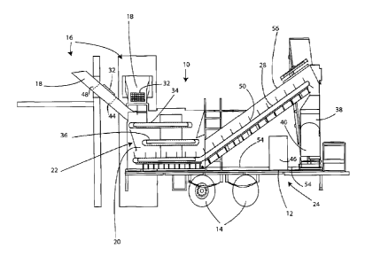
BRIEF DESCRIPTION OF THE DRAWINGS
Figure 1 is a side view cross section of an embodiment of the disclosed
technology.
Figure 2 is a perspective cross section of an embodiment of the disclosed
technology.
Figure 3 is a perspective cross section of an embodiment of the disclosed
technology
which includes a grinder.
DETAILED DESCRIPTION OF THE PREFERRED EMBODIMENTS
While the presently disclosed inventive concept(s) is susceptible of various
modifications and alternative constructions, certain illustrated embodiments
thereof have been
shown in the drawings and will be described below in detail. The scope of the
claims should not
be limited by the preferred embodiments set forth in the examples, but should
be given the
broadest interpretation consistent with the description as a whole.
Preferred embodiments of the disclosed technology are shown in the Figures.
Figure 1
shows the euthanasia device 10, referred to as the hen sleeper 10. The hen
sleeper 10 is
mounted on the trailer 12 which is transported by use of wheels 14. The hen
sleeper 10 is
positioned adjacent to a hen house 16 as an example. An entry chute 18 is
inserted through
the wall of the hen house 16 for entry of hens into the hen sleeper 10.
Included on the entry
- 10-
CA 02880970 2015-08-27
chute 18 is a vacuum break 32 which may be a metal screen covering a hole in
the chute.
Between the hen sleeper 10 and the vacuum break 32 is positioned a first air
curtain 44. The
first air curtain can be a brush which extends from the top and bottom of the
chute. Hens can
easily pass between the brushes of the air curtain, and enter the hen sleeper.
Between the
vacuum break 32 and the hen house 16 is a second air curtain 48. If the hen
house has a
negative air pressure it will tend to draw air from the hen sleeper into the
hen house. The
vacuum break provides a path of less resistance for air to be drawn into the
hen house. The air
curtains increase resistance to air from the hen sleeper being drawn into the
hen house.
One configuration of the hen sleeper 10 uses 3 moving belts to move hens into
and
through the hen sleeper 10. A first moving belt 34 is directly below the entry
chute 18, and
hens drop onto the first moving belt from the entry chute. The hens move
toward the right on
the belt as shown in Fig. 1., in a low CO2 atmosphere, and drop onto the 2nd
moving belt 36.
This belt moves from right to left as shown in Fig. 1, and is in a higher
concentration of CO2.
From 2nd moving belt 36, the hens drop onto the lifting conveyor 28, and move
to the
right as seen in Fig. 1. In one configuration, the lifting conveyor can be a
belt with attached
paddles, which prevent the hens from sliding down the lifting conveyor. The
region there the
belt are located is called the lst gas reservoir, and is gas proof except for
the end of the entry
chute. CO2 gas accumulates and stays in the 15t gas reservoir, and the hens
pass through the
CO2 rich region.
Shown in Fig. 1 is a CO2 canister 46 and the gas lines 54 that make up the
toxic gas
injection system 52. A CO2 canister 46 with liquid CO2 forms the toxic gas
source. The gas lines
54 go at least to the bottom of the 1st gas reservoir 20, and inject liquid
CO2 into the 1st gas
- 11 -
CA 02880970 2015-08-27
reservoir 20, where it volatilizes and become gaseous CO2. CO2 liquid can also
be injected at
the top of the lifting conveyor 28, and between belts 34 and 36. The CO2 is
pressurized in the
gas lines and exits a jet as a liquid under pressure, and the release site.
CO2 sensors are present
at several locations, and can trigger an alarm which warns operators that CO2
concentrations
are lower than required. The alarm can shut off the belts, so that hens are
assured of enough
residence time in a high CO2 environment to not revive. Gas injectors are
present in at least the
1st gas reservoir 20, and also at top of the lifting conveyor 28, and
optionally between the 1st
moving belt 34 and the second moving belt 36. A generator 58 is present which
powers the
motors which drive the belts.
A typical configuration of the hen sleeper is mounted on a flatbed trailer 12
which can
be approximately 96 inches wide and 240 inches long. The chamber which houses
the first and
second moving belt is typically approximately 36 inches wide, 96 inches long
and 60 inches tall.
The entry chute 18 may be 12 inches tall and 72 inches long and 48 to 32
inches wide. The
entry chute 18 can be attached to two or more attachment points as shown in
Figure 1. This
allows the hen sleeper to attach to a hen house directly behind the trailer
and to either side of
the trailer. The first moving belt 34 is preferably a belt of linked plastic
plates, which minimizes
pinch points and hang-up points. In one configuration, the first moving belt
34 is 32 inches
wide and 72 inches long. In the same embodiment, the second moving belt 36 can
be 36 inches
wide and 72 inches long. In the same embodiment, lifting conveyor 3rd belt 28
can have a
horizontal portion which is about 36 inches wide and 96 inches long, and a
sloping portion
which is 12 feet long. The paddles or flights 50 for this configuration can be
6 inches extending
from the belt and is as wide as the belt.
- 12 -
CA 02880970 2015-08-27
Fig. 2 shows more of the front end of the hen sleeper, and where the exit
chute 56
drops into a collection tube 38. CO2 gas can be injected into the top of chute
56, and provides a
2nd gas reservoir and more exposure time for the hens to be in a high CO2
concentration area.
The bottom of collection tube 38 can be attached to a delivery belt 42, and a
sealed delivery
chute 60, which moves the hens to a point to be deposited in a transfer
vehicle of some kind.
The delivery chute 60 is configured to rotate around the collection tube 38,
and can thus swing
180 degrees or more around the tongue of the trailer. An optional grinder 62
can be placed at
the exit of the delivery chute 60, or at the end of the exit chute, so that
hens are ground into
pieces upon leaving the hen sleeper 10, and before entering the transport
vehicle.
Figure 3 shows a version in which the collection tube, delivery belt and
delivery chute
are replaced by a grinder 62, which is attached to a slurry pump 66 and a
slurry hose 64, with
the dead birds ground into a slurry in the grinder, and pumped to a transport
vehicle.
The scope of the claims should not be limited by the preferred embodiments set
forth in
the examples, but should be given the broadest interpretation consistent with
the description
as a whole.
- 13 -