Note: Descriptions are shown in the official language in which they were submitted.
SHOCK WAVE CATHETER SYSTEM WITH ARC PRECONDITIONING
BACKGROUND
[0002] The present invention relates to a treatment system for percutaneous
coronary
angioplasty or peripheral angioplasty in which a dilation catheter is used to
cross a lesion in
order to dilate the lesion and restore normal blood flow in the artery. It is
particularly useful
when the lesion is a calcified lesion in the wall of the artery.
[0003] Calcified lesions, currently treated with angioplasty balloons, require
high pressures
(sometimes as high as 10-15 or even 30 atmospheres) to break the calcified
plaque and push it
back into the vessel wall. With such pressures comes trauma to the vessel wall
which can
contribute to vessel rebound, dissection, thrombus formation, and a high level
of restenosis.
Non-concentric calcified lesions can result in undue stress to the free wall
of the vessel when
exposed to high pressures. An angioplasty balloon when inflated to high
pressures can have a
specific maximum diameter to which it will expand but the opening in the
vessel under a
concentric lesion will typically be much smaller. As the pressure is increased
to open the
passage way for blood the balloon will be confined to the size of the opening
in the calcified
lesion (before it is broken open). As the pressure builds a tremendous amount
of energy is stored
in the balloon until the calcified lesion breaks or cracks. That energy is
then released and results
in the rapid expansion of the balloon to its maximum dimension and may stress
and injure the
vessel walls.
[0004] Recently, a new system and method has been contemplated for breaking up
calcium
deposits in, for example, arteries and veins. Such a system is described, for
example in U.S.
Patent Publication No. 2009/0312768, Published December 17, 2009. Embodiments
described
therein include a catheter having balloon, such as an angioplasty balloon, at
the distal end
thereof, arranged to be inflated with a fluid. Disposed within the balloon is
a shock wave
1
CA 2881191 2018-03-06
CA 02881191 2015-02-04
WO 2014/028885 PCT/US2013/055431
generator that may take the form of, for example, a pair of electrodes, which
are coupled to a
high voltage source at the proximal end of the catheter through a connector.
When the
balloon is placed adjacent a calcified region of a vein or artery and a high
voltage pulse is
applied across the electrodes, a shock wave is formed that propagates through
the fluid and
impinges upon the wall of the balloon and the calcified region. Repeated
pulses break up the
calcium without damaging surrounding soft tissue.
[0005] Each high voltage pulse causes an arc to form across the electrodes.
The arc in turn
causes a steam bubble to form. Each arc results in intense heat and energy for
a brief period of
time. Inside the small confines of tiny angioplasty balloons the fluid can
warm up and become
hot enough to damage tissue unless steps are taken to control the amount of
energy released into
the fluid. Just a two degree Celsius elevation in temperature above body
temperature can result
in tissue damage.
[0006] The amount of energy to assure the formation of the steam bubble and
arc can be
highly variable from arc to arc. Therefore, if the same amount of energy is
used to assure the
formation of each bubble and arc, more energy than is necessary will be used
to form many of
the bubbles and arcs. Excessive heating of the fluid within the balloon may
result. Also, because
greater applied energies create larger bubbles at the electrodes, the
excessive energy will
produce a larger bubble than required which can unduly stress the balloon
walls.
[0007] Another consideration is the amount of energy represented by the high
voltage applied
to the electrodes. Each high voltage pulse removes a portion of the electrode
material. Since the
size of the electrodes must be small in order to fit into the calcified vein
or artery, they are only
capable of sustaining a limited numbers of high voltage pulses sufficient to
form the shock wave
resulting electrical arc.
[0008] Hence, there is a need in the art to be able to control the amount of
energy required to
produce the bubbles and arcs. It would also be desirable to be able to produce
the bubbles and
arcs with less energy than hereto for possible. The present invention
addresses these and other
issues.
2
CA 02881191 2015-02-04
WO 2014/028885 PCT/US2013/055431
BRIEF SUMMARY
[0009] In one embodiment, a shock wave catheter system includes a catheter and
a power
source. The catheter has an elongated carrier and a balloon about the carrier
in sealed relation
thereto. The balloon is arranged to receive a fluid therein that inflates the
balloon. The catheter
further includes an arc generator including at least two electrodes within the
balloon. The power
source is configured to deliver a first electrical voltage across the at least
two electrodes that
grows a bubble at one of the at least two electrodes and then thereafter
delivers a second
electrical voltage across the at least two electrodes to create an arc across
the at least two
electrodes to rapidly expand the bubble to form a shock wave within the
balloon.
[0010] The second electrical voltage is significantly greater than the first
electrical voltage.
The first electrical voltage is on the order of 50 volts and the second
electrical voltage is between
300 and 10,000 volts.
[0011] The power source may be configured to hold the first electrical voltage
for a first time
period and to hold the second electrical voltage for a second time period, the
first time period
being significantly longer in length than the second time period. The first
time period may on
the order of two milliseconds and the second time period may be on the order
of one-half
microsecond.
[0012] The balloon may be an angioplasty balloon.
[0013] According to other embodiments, a shock wave catheter system includes a
catheter and
a power source. The catheter has an elongated carrier and a balloon about the
carrier in sealed
relation thereto. The balloon is arranged to receive a fluid therein that
inflates the balloon. The
catheter further has an arc generator including at least two electrodes within
the balloon. The
power source is coupled to the at least two electrodes and is configured to
grow a bubble at one
of the at least two electrodes and then thereafter to rapidly expand the
bubble to form a shock
wave within the balloon.
[0014] In another embodiment, a method of producing an electrohydraulic shock
wave
includes growing a bubble within a fluid during a first time period and
thereafter, rapidly
expanding the bubble during a second time period.
3
CA 02881191 2015-02-04
WO 2014/028885 PCT/US2013/055431
[0015] The growing step may include providing at least two electrodes within
the fluid and
delivering a first voltage to the at least two electrodes during a first time
period.
[0016] The expanding step may include delivering a second voltage to the at
least two
electrodes during a second time period. The second voltage may be greater than
the first voltage
and the first time period may be longer than the second time period. The
second voltage may be
between 300 and 10,000 volts. The first time period may be on the order of two
milliseconds and
the second time period may be on the order of one-half microsecond.
BRIEF DESCRIPTION OF THE DRAWINGS
[0017] The features of the present invention which are believed to be novel
are set forth with
particularity in the appended claims. The invention, together with further
features and
advantages thereof, may best be understood by making reference to the
following description
taken in conjunction with the accompanying drawings, in the several figures of
which like
reference numerals identify identical elements, and wherein:
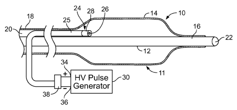
[0018] FIG. 1 is a simplified side view of an a shock wave catheter system
embodying various
embodiments of the invention to advantage;
[0019] FIG. 2 is a simplified view, partly in perspective, of the electrode
structure and power
source employed in the catheter of FIG. 1;
[0020] FIG. 3 is a graph illustrating typical voltage and current waveforms of
voltage and
current to form an electrohydraulic shock wave between a pair of electrodes as
practiced in the
prior art;
[0021] FIG. 4 is a simplified view, to an enlarged scale, illustrating the
growth of a large
bubble at an electrode;
[0022] FIG. 5 is a simplified view, to an enlarged scale, illustrating the
growth of a small
bubble at an electrode;
[0023] FIG. 6 is a schematic diagram of a power source for use in an
angioplasty electrical arc
shock wave angioplasty catheter system according to an embodiment of the
invention; and
4
CA 02881191 2015-02-04
WO 2014/028885 PCT/US2013/055431
[0024] FIG. 7 is a graph illustrating voltage and current waveforms of voltage
and current
which may be derived from the power circuit of FIG. 6 to form an
electrohydraulic shock wave
between a pair of electrodes as practiced according to an embodiment of the
invention.
DETAILED DESCRIPTION
[0025] FIG. 1 is a simplified side view of an angioplasty balloon catheter
system 10 of the
type that may utilize various embodiments of the invention to advantage. The
system 10 includes
a catheter 11 and a power source 30.
[0026] The catheter 11 includes an elongated carrier, such as a hollow sheath
12 and a dilating
balloon 14 formed about the sheath 12 in sealed relation thereto at a seal 16.
The balloon 14 has
a tubular extension 18 which forms with the sheath 12 a channel 20 for
admitting a fluid into the
balloon 14. The sheath 12 has a longitudinal lumen 22 through which a guide
wire (not shown)
may be received for directing the catheter 11 to a desired location within a
vein or artery, for
example.
[0027] The catheter 11 further includes an arc generator 24 within the balloon
14. The arc
generator, as may be best seen in FIG. 2, includes a lead 25 having a
coaxially configured
electrode pair including electrodes 26 and 28. As may be seen in FIG. 2.
electrode 26 forms a
center electrode and electrode 28 forms a ring shaped electrode concentrically
disposed about
the center electrode 26. As mentioned above, the sheath 12 forms with the
balloon extension 18
a channel 20 through which fluid, such as saline, may be admitted into the
balloon to inflate the
balloon. The channel 20 further permits the electrodes 26 and 28 of lead 25 to
be fed into the
balloon 14.
[0028] As may be seen in FIGS. 1 and 2, the electrodes 26 and 28 are attached
to a source 30
of high voltage pulses. As may be seen in FIG. 2. the center electrode 26 is
coupled to a positive
terminal 34 of source 30 and the ring electrode 28 is coupled to a negative
terminal 36 of the
source 30. The electrodes 26 and 28 may be formed of metal, such as stainless
steel, and are
maintained a controlled distance apart to allow a reproducible arc to form for
a given applied
voltage and current.
[0029] The electrical arcs between electrodes 26 and 28 in the fluid are used
to generate shock
waves in the fluid. Each pulse of high voltage applied to the electrodes 26
and 28 forms an arc
CA 02881191 2015-02-04
WO 2014/028885 PCT/US2013/055431
across the electrodes. The voltage pulses may have amplitudes as low as 500
volts, but
preferably, the voltage amplitudes are in the range of 1000 volts to 10,000
volts The balloon 14
may be filled with water or saline in order to gently fix the balloon in the
walls of the artery or
vein, for example, in direct proximity with the calcified lesion. The fluid
may also contain an x-
ray contrast to permit fluoroscopic viewing of the catheter during use. Once
the catheter 11 is
positioned with the guide wire (not shown), the physician or operator can
start applying the high
voltage pulses to the electrodes to form a plurality of discrete shock waves
that crack the
calcified plaque. Such shock waves will be conducted through the fluid,
through the balloon,
through the blood and vessel wall to the calcified lesion where the energy
will break the
hardened plaque without the application of excessive pressure by the balloon
on the walls of the
artery.
[0030] FIG. 3 is a graph illustrating typical voltage (solid line) and current
(dashed line)
waveforms of voltage and current if traditional prior art techniques are
employed to form an
electrohydraulic shock wave between a pair of electrodes, such as electrodes
26 and 28. Here it
may be seen by reference character 40 that a voltage of 3,000 volts is applied
between the
electrodes. A low level current 42 flows through the water creating a bubble
on the electrodes.
After a delay D, for example one microsecond, at 44, an arc jumps across the
bubble. In this
example, the arc is 200 amperes and jumps between the electrodes. When the arc
starts, the
voltage drops quickly and when the voltage pulse is terminated at 46, it drops
to zero. In this
prior art methodology, the delay D is highly variable and has been measured to
be as short as
ninety nanoseconds to as long as 1000 nanoseconds. The delay D is also
unpredictable from
pulse to pulse. The shock wave is generated when the arc current occurs at 44.
Since the delay D
is unpredictable, the voltage pulse must be have a duration long enough to
assure an arc will
form. In the example, that duration is about 1.8 microseconds. The net result
of a fixed long
voltage is that more energy is applied to each pulse than is needed to assure
the occurrence of an
arc. The excess energy needlessly heats the fluid in the balloon.
[0031] FIGS. 4 and 5 illustrate the cause of the variable delay D. Sometimes,
as shown in
FIG. 4, a large bubble 50 is formed before the arc 60 occurs. However, at
other times, a small
bubble 52 is formed before the arc 60 occurs causing the arc to occur more
quickly. The bubbles
are formed by electrolysis of the fluid and a large bubble takes longer to
form than a small
6
CA 02881191 2015-02-04
WO 2014/028885 PCT/US2013/055431
bubble. The arc occurs when the voltage across the bubble is sufficient to arc
the gap and is
highly variable.
[0032] FIG. 6 is a schematic diagram of a power source 30 for use in an
angioplasty electrical
arc shock wave angioplasty catheter system according to an embodiment of the
invention. As
will be seen, the power source delivers a first low voltage across the
electrodes to pre-grow the
bubble at one of the electrodes and thereafter delivers a second higher
voltage across the
electrodes to rapidly expand the pre-grown bubble to cause the arc and the
shock wave in a time
controlled manner.
[0033] The source 30 includes control logic 70, a first transistor 72, a
second transistor 74, and
output terminals 76 and 78. Output terminal 76 is arranged to coupled through
a connector 38
(FIG.1) to the center electrode 26 (FIG. 2) of the shock wave generator 24 and
output 78 is
arranged to be coupled through the connector to the outer electrode 28 of the
shock wave
generator. The output terminal is connected to a 3,000 volts source.
[0034] Initially, the control logic 70 delivers a two millisecond (2 ms)
control pulse 80 to the
gate of transistor 72. This causes a low (for example, 25ma) current through
the electrodes and a
resistor 73. The low current applied for 2 ms forms a bubble on one of the
electrodes of a
predictable size. After the 2 ms, the control logic 70 turns transistor 74 on
hard for 500
nanoseconds (500 ns). This applies the full 3,000 volts to the electrodes. The
control logic 70
may turn transistor 74 on hard immediately after the 2 ms period or a short
time thereafter, as for
example, 10 microseconds after the 2 ms period. An arc and shock wave will
occur essentially
immediately. Since the high voltage is applied for only a short time, here 500
ns, a reduced
amount of energy is delivered to the fluid within the balloon for generating
each shock wave. As
a result, much less heat is generated in the fluid within the balloon.
[0035] FIG. 7 is a graph illustrating voltage and current waveforms of voltage
(solid line) and
current (dashed line) which may be derived from the power source 30 of FIG. 6
to form an
electrohydraulic shock wave between the pair of electrodes 26 and 28 as
practiced according to
the embodiment of FIG. 6. First, a low voltage 90 is applied across the
electrodes when
transistor 72 is turned on for 2 ms. The low voltage assures that an arc will
not occur across the
electrodes. However, the low voltage does produce a low current 92 (25 ma) to
flow through the
electrodes. During this 2 ms period, a bubble of predictable size is grown on
one of the
7
CA 02881191 2015-02-04
WO 2014/028885 PCT/US2013/055431
electrodes. The bubble size may be controlled by the amount of current and the
length of time
the low current is applied. After the 2 ms period, the transistor 74 is turned
on hard to apply a
narrow pulse (500 ns) of the full 3,000 volt high voltage 94 across the
electrodes. During this
short time, a current of 250 amperes may flow between the electrodes. The high
voltage and
current rapidly expands the pre-grown bubble and within a short delay time DT
causes the arc
and shock wave to be produced at 96. The arc and shock wave are produced
quickly because the
bubble had already been pre-grown by the low voltage 90. The voltage and
current fall quickly
to zero at 98.
[0036] As may be seen from the foregoing, the high voltage pulse is applied
for a much
shorter period of time to produce the arc and shock wave because the bubble
had already been
pre-grown by the preceding low voltage and current. The overall arc energy is
lower and the
steam bubble will be smaller. This results in less energy being applied to the
fluid within the
balloon for each generated shock wave. The fluid is therefore heated less and
there is less stress
on the wall of the balloon.
[0037] While particular embodiments of the present invention have been shown
and described,
modifications may be made. It is therefore intended in the appended claims to
cover all such
changes and modifications which fall within the true spirit and scope of the
invention as defined
by those claims.
8