Note: Descriptions are shown in the official language in which they were submitted.
CA 02881451 2015-02-06
WO 2014/031774 PCT/US2013/056034
BLOOD CONTROL IV CATHETER WITH
ANTIMICROBIAL PROPERTIES
BACKGROUND OF THE INVENTION
[0001] The
current invention relates to systems and methods for coating various
surfaces of medical devices with an anti-pathogenic material. In particular,
the
present invention relates to systems and methods for applying anti-pathogenic
material to select interior surfaces to reduce or eliminate pathogenic
colonization and
growth within the medical device.
[0002] A
formidable challenge of modem medical treatment is control of infection
in the spread of pathogenic organisms. One area where this challenge is
constantly
presented is in infusion therapy of various types. Infusion therapy is one of
the most
common healthcare procedures. Hospitalized, home care, and other patients
receive
fluids, pharmaceuticals, and blood products via a vascular access device
inserted into
the vascular system of the patient. Infusion therapy may be used to treat an
infection,
provide anesthesia or analgesia, provide nutritional support, treat cancerous
growths,
maintain blood pressure and heart rhythm, or many other clinically significant
uses.
[0003] Infusion
therapy is facilitated by a vascular access device. The vascular
access device may access the patient's peripheral or central vasculature. The
vascular
access device may be indwelling for short-term (days), moderate term (weeks),
or
long-term (months to years). The vascular access device may be used for
continuous
infusion therapy or for intermittent therapy.
[0004] A common
vascular access device comprises a plastic catheter inserted into
a patient's vein. The catheter length may vary from a few centimeters for
peripheral
access, to many centimeters for central access and may include devices such as
peripherally inserted central catheters (PICC). The catheter may be inserted
transcutaneously or may be surgically implanted beneath the patient's skin.
The
catheter, or any other vascular access device attached thereto, may have a
single
lumen or multiple lumens for infusion of many fluids simultaneously.
[0005] A vascular
access device may serve as a nidus, resulting in a disseminated
BSI (blood stream .................................................
infection). This may be caused by failure to regularly flush the
device, a non-sterile insertion technique, or by pathogens that enter the
fluid flow path
through either end of the path subsequent to catheter insertion. When a
vascular
access device is contaminated, pathogens adhere to the vascular access device,
-Page 1-
CA 02881451 2015-02-06
WO 2014/031774 PCMJS2013/056034
colonize, and form a biofilm. The biofilm is resistant to most biocidal agents
and
provides a replenishing source of pathogens to enter a patient's bloodstream
and cause
a BSI.
[0006] One approach to preventing biofilm formation and patient infection
is to
provide an anti-pathogenic coating on various medical devices and components.
However, some medical devices and components comprise materials or features
which are incompatible with anti-pathogenic coatings. Thus, although methods
exist
for providing an anti-pathogenic coating on various medical devices and
components,
challenges still exist. Accordingly, it would be an improvement in the art to
augment
or even replace current techniques with other techniques. Such techniques are
disclosed herein.
BRIEF SUMMARY OF THE INVENTION
[0007] In order to overcome the limitations discussed above, the present
invention
relates to systems and methods for selectively coating surfaces of medical
devices that
contact blood or other fluids as part of an infusion therapy.
[0008] Some implementations of the present invention include a medical
device
having a fluid pathway. A septum is slidably housed within the fluid pathway.
A
septum actuator is disposed in a fixed position within the fluid pathway. In
operation,
the septum can be advanced toward the septum actuator, which can pierce the
septum,
opening the septum and permitting fluid flow therethrough. In some examples,
both
the septum actuator and the septum have at least one surface exposed to the
fluid
pathway. An anti-pathogenic material can be applied to these surfaces.
[0009] In some instances, the septum has a tubular shape and has a barrier
member. The septum can thus form a proximal cavity. The barrier member can
have
a slit extending between a distal and proximal side of the barrier member. The
barrier
member can divide the septum into the proximal cavity and a distal cavity, and
a
portion of the septum actuator can be disposed within the distal cavity.
[0010] In some implementations, an anti-pathogenic material including a
lubricant
agent is applied to the probe portion of the septum actuator to reduce
friction between
the septum actuator and the septum during activation of the device. In other
implementations, a rigid or semirigid anti-pathogenic material is applied to
various
surfaces of a base portion of the septum actuator.
-Page 2-
CA 02881451 2015-02-06
WO 2014/031774 PCT/US2013/056034
[0011] Certain aspects of the present invention further include a color
code system,
whereby the identity of the anti-pathogenic material is identified based upon
the color
of the medical device.
[0012] In other aspects of the present invention, a ventilation channel can
be
interposed between the septum and an inner surface of the infusion therapy
device.
The anti-pathogenic material can be applied to a surface of the ventilation
channel.
The anti-pathogenic material applied to the surface of the ventilation channel
can have
a thickness less than that which would occlude the ventilation channel to
permit
venting through the ventilation channel.
[0013] Some aspects of the present invention include a medical device
having a
compatible surface that includes at least one mechanical bond to facilitate
binding
between the surface and an anti-pathogenic material. Other aspects of the
invention
include providing a chemical bond between a compatible surface of a medical
device
and an anti-pathogenic material by surface cross-linking.
[0014] The present invention further includes various methods, techniques,
and
materials for identifying and coating surfaces of medical devices which
include
noncritical dimensions. Thus, an anti-pathogenic material may be applied to
various
surfaces within a medical device to reduce or eliminate pathogenic
colonization
and/or growth within the medical device thereby reducing the risk of
pathogenic
infection in patients.
BRIEF DESCRIPTION OF THE SEVERAL VIEWS OF THE DRAWINGS
[0015] In order that the manner in which the above-recited and other
features and
advantages of the invention are obtained will be readily understood, a more
particular
description of the invention briefly described above will be rendered by
reference to
specific embodiments thereof which are illustrated in the appended drawings.
These
drawings depict only typical embodiments of the invention and are not
therefore to be
considered to limit the scope of the invention.
[0016] Figure 1 is a cross-section view of a catheter assembly comprising a
septum
and septum actuator prior to activation, the catheter assembly, septum, and
septum
actuator having various surfaces with critical and noncritical dimensions in
accordance with a representative embodiment of the present invention.
[0017] Figure 2 is a cross-section view of the catheter assembly of Figure
1, with
the septum and anti-pathogenic material removed, showing internal ventilation
channels in accordance with a representative embodiment of the present
invention.
-Page 3-
CA 02881451 2015-02-06
WO 2014/031774 PCT/US2013/056034
[0018] Figure 3 is a cross-section view of the catheter assembly of Figure
1
comprising a septum and septum actuator following activation in accordance
with a
representative embodiment of the present invention.
[0019] Figure 4 is a partial, cross-section view of a catheter assembly
comprising
an alternative septum and septum actuator in accordance with a representative
embodiment of the present invention.
[0020] Figure 5 is a partial, cross-section view of a catheter assembly
comprising
another alternative septum and septum actuator in accordance with a
representative
embodiment of the present invention.
[0021] Figure 6 is a partial, cross-section view of a catheter assembly
comprising
yet another alternative septum and septum actuator in accordance with a
representative embodiment of the present invention.
[0022] Figure 7 is a cross-section view of an isolated septum in accordance
with a
representative embodiment of the present invention.
DETAILED DESCRIPTION OF THE INVENTION
[0023] The presently preferred embodiment of the present invention will be
best
understood by reference to the drawings, wherein like reference numbers
indicate
identical or functionally similar elements. It will be readily understood that
the
components of the present invention, as generally described and illustrated in
the
figures herein, could be arranged and designed in a wide variety of different
configurations. Thus, the following more detailed description, as represented
in the
figures, is not intended to limit the scope of the invention as claimed, but
is merely
representative of presently preferred embodiments of the invention.
[0024] The term "proximal" is used to denote a portion of a device which,
during
normal use, is nearest the user and furthest from the patient. The term
"distal" is used
to denote a portion of a device which, during normal use, is farthest away
from the
user wielding the device and closest to the patient. The term "activation" of
valve
mechanism or septum is used to denote the action of opening or closing of such
valve.
For example, in some embodiments a catheter assembly is provided having a
septum
and a septum actuator, wherein the catheter assembly undergoes activation when
the
septum actuator is advanced through the septum, thereby providing a fluid
pathway
through the septum.
[0025] The term "critical dimension" is used to denote at least one of a
height, a
length, a width, a depth, a diameter, a thickness, an angle, a texture, or
other structural
-Page 4-
CA 02881451 2015-02-06
WO 2014/031774 PCT/US2013/056034
feature of a surface of a medical device which is critical to the operation of
the device.
For example, in some embodiments a medical device may include a surface that
is
configured to interface with another device or component. As such, the surface
may
include a critical dimension that is configured to accommodate optimal
interaction
between the surface of the medical device and the interfacing device or
component.
Thus, in some embodiments a surface having a critical dimension must remain
unmodified to preserve the intended and/or desired interaction of the surface
in
operating or using the medical device. Conversely, the term "noncritical
dimension"
is used to denote at least one of a height, a length, a width, a depth, a
diameter, a
thickness, an angle, a texture, or other structural feature of a medical
device with is
not critical to the operation of the device.
[0026] The terms "chemical bond" or "chemical bonding" are used to denote
an
attraction between atoms that allows an anti-pathogenic material to be applied
to a
desired surface of a medical device. For example, in some instances an anti-
pathogenic material of the present invention is applied to the surface of an
infusion
therapy medical device via chemical bonding, wherein atoms of the anti-
pathogenic
material and atoms of the medical device are chemically attracted to one
another.
Chemical bonding may include any type of atomic bond, such as a covalent bond,
an
ionic bond, dipole-dipole interactions, London dispersion force, Van der Waals
force,
and hydrogen bonding. A chemical bond may further be denoted by the terms
"cross-
linking" or "surface cross-linking" for some embodiments.
[0027] The terms "mechanical bond" or "mechanical bonding" are used to
denote
a physical, non-chemical interaction between two or more materials. For
example, in
some instances a surface of a medical device is altered to include a texture,
a groove,
and/or a ridge having a void which holds an anti-pathogenic material via
capillary
force. In other embodiments, a mechanical bond comprises a structural feature
which
provides increased surface area to a surface of a medical device. Further, in
some
embodiments, a mechanical bond comprises a hydrophilic or hydrophobic material
or
coating that is applied to a surface of a medical device to attract an anti-
pathogenic
material. A mechanical bond may further be denoted by the term "mechanical
interlock" for some embodiments.
[0028] The term "compatible surface" is used to denote a surface of a
medical
device which includes a noncritical dimension, or a surface which includes a
critical
-Page 5-
CA 02881451 2015-02-06
WO 2014/031774 PCT/US2013/056034
dimension that will not be adversely affected by the addition of an anti-
pathogenic
material or coating.
[0029] The terms "rigid" or "semirigid" are used to denote a physical
property of
an anti-pathogenic material, wherein the material is deficient in, or devoid,
or mostly
devoid of flexibility. Alternatively, these terms are used to denote an
inflexible or
mostly inflexible physical property of an anti-pathogenic material when
applied or
coated onto a surface of a device. In some instances, the term semirigid is
understood
to describe a physical property of an anti-pathogenic material that is rigid
to some
degree or in some parts.
[0030] The term "modified theology" is used to denote a physical property
of an
anti-pathogenic material, wherein the viscosity of an anti-pathogenic material
is
modified to prevent excessive migration of the anti-pathogenic material once
applied
to a surface of a device. As such, the modified 'Theology of the anti-
pathogenic
material prevents or substantially prevents contact between the anti-
pathogenic
material and adjacent surfaces or components.
[0031] The term "anti-pathogenic" is used to denote a material, such as a
coating
material, that acts against pathogens. Pathogens may include any organism or
substance capable of causing a disease, such as bacteria, viruses, protozoa
and fungi.
Accordingly, an "anti-pathogenic material" as contemplated herein includes any
material having properties for acting against a pathogen.
[0032] The present invention relates generally to systems and methods for
applying anti-pathogenic materials to various surfaces of medical devices. In
particular, the present invention relates to systems and methods for applying
anti-
pathogenic materials to surfaces of medical devices for infusion therapies,
wherein the
surface comprises a portion of a fluid pathway of the medical device. In some
instances, an anti-pathogenic material is applied to a surface comprising a
noncritical
dimension. In some embodiments, an anti-pathogenic material is applied to one
or
more surfaces of a medical device prior to assembling the medical device. In
other
embodiments, an anti-pathogenic material is applied to the first portion or
component
of a medical device and subsequently transferred to a second portion or
component of
the medical device through controlled migration of the anti-pathogenic
material. In
other instances, an anti-pathogenic material is intermixed with, or
incorporated into
the material of the medical device during a molding process of the device.
Further, in
some instances an anti-pathogenic material is applied to or incorporated into
the
-Page 6-
material of a medical device such that the anti-pathogenic material elutes out
from the
material of the medical device into the immediate surroundings of the coated
medical
device.
10033] In general, an anti-pathogenic material in accordance with the
present
invention may include any material having anti-pathogenic properties which may
be
applied to the surface of a medical device, such as an infusion therapy
device. For
example, in some embodiments an anti-pathogenic material may include an
antimicrobial composition, as taught in United States Patent Applications
serial nos.
12/397,760, 11/829,010, 12/476,997, 12/490,235, and 12/831,880. In some
embodiments, an anti-pathogenic material may further include an anti-infective
or
antimicrobial lubricant, as taught in United States Patent Applications serial
nos.
12/436,404 and 12/561,863. Further, in some embodiments an anti-pathogenic
material is incorporated into the material of a medical device, or a component
thereof,
such as a septum actuator.
100341 Some embodiments of the present invention comprise a medical
device or
component having at least one surface that defines a portion of a fluid
pathway
through the medical device, such as an infusion therapy device (e.g., a
catheter
assembly or Luer adapter). The surface of the medical device is coated with an
anti-
pathogenic material to prevent colonization of pathogens on the coated
surface.
[0035] The application of an anti-pathogenic material to the surface
of a medical
device results in the addition of a layer or "coat" of anti-pathogenic
material to the
surface. This layer of anti-pathogenic material has a dimension (i.e.
thickness) which
may affect a relationship between the coated surface and an interfacing or
adjacent
component of the medical device. For example, in some embodiments a medical
device may include an aperture having a diameter to compatibly receive a
second
medical device, such as by a friction, press, mechanical or interference fit.
As such,
the diameter of the aperture includes critical dimensions to ensure proper
fitting
between the aperture and the second medical device. In this example, the
addition of
an anti-pathogenic material to the surface of the aperture will adjust the
diameter of
the aperture thereby adversely affecting the ability of the aperture to
receive the
second medical device.
100361 Accordingly, in some embodiments of the present invention it is
undesirable to modify or coat a surface of a medical device or component
wherein the
-Page 7-
CA 2881451 2019-05-27
CA 02881451 2015-02-06
WO 2014/031774 PCT/US2013/056034
surface includes a critical dimension that will be adversely affected by the
addition of
the anti-pathogenic material. Thus, some embodiments of the present invention
comprise a method for coating a medical device with an anti-pathogenic
material,
wherein the method includes a first step of identifying surfaces of the
medical device
which include noncritical dimensions. The method may further include a step
whereby the surfaces having noncritical dimensions are then coated with an
anti-
pathogenic material. Some methods of the present invention may further include
steps for identify and isolating surfaces of the medical device having
critical
dimensions, prior to coating the remaining surfaces with an anti-pathogenic
material.
[0037] In further
examples of the teachings of the present invention, a catheter
assembly device 10 is shown in Figures 1-3. Catheter assembly device 10
provides a
non-limiting example of a medical device having various surfaces which may be
coated with an anti-pathogenic material. Accordingly, catheter assembly device
10
provides a representative embodiment on which to demonstrate and discuss the
methodologies of the present invention relating to the selection and coating
of
surfaces with an anti-pathogenic material.
[0038] Referring
now to Figure 1, a cross-section view of a catheter assembly 10 is
shown. Catheter assembly 10 generally includes a catheter 12 coupled to a
distal end
22 of a catheter adapter 20. Catheter 12 and catheter adapter 20 are
integrally coupled
such that an internal lumen 26 of catheter adapter 20 is in fluid
communication with a
lumen 14 of catheter 12. Catheter 12 generally comprises a biocompatible
material
having sufficient rigidity twisting pressures associated with insertion of the
catheter
into a patient. In some embodiments, catheter 12 comprises a metallic
material, such
as titanium, stainless steel, nickel, molybdenum, surgical steel, and alloys
thereof. In
other embodiments, catheter 12 comprises a rigid, polymer material, such as
vinyl or
silicon.
[0039] Catheter
assembly 10 may further include features for use with an over-the-
needle catheter assembly. For example, a flexible or semi flexible polymer
catheter
may be used in combination with a rigid introducer needle to enable insertion
of the
catheter into the vasculature of a patient. Surgically implanted catheters may
also be
used.
[0040] Once
inserted into a patient, catheter 12 and catheter adapter 20 provide a
fluid conduit to facilitate delivery of a fluid to and/or retrieval of a fluid
from a
patient, as required by a desired infusion procedure. Thus, in some
embodiments the
-Page 8-
CA 02881451 2015-02-06
WO 2014/031774 PCT/US2013/056034
material of the catheter 12 and the catheter adapter 20 are selected to be
compatible
with bio-fluids and medicaments commonly used in infusion procedures.
Additionally, in some embodiments a portion of the catheter 12 and/or catheter
adapter 20 is configured for use in conjunction with a section of intravenous
tubing
(not shown) to further facilitate delivery of a fluid to or removal of a fluid
from a
patient.
[0041] The various embodiments of the present invention may be adapted for
use
with any medical device or accessory having a lumen in which is placed a
septum.
For example, in some embodiments a female Luer adapter coupled to a section of
intravenous tubing may comprise a septum and a septum actuator in accordance
with
the present teachings. In other embodiments, one or more ends of a y-port
adapter
may comprise a septum and a septum actuator in accordance with the teachings
of the
present invention.
[0042] In some embodiments, a proximal end 24 of the catheter adapter 20
includes a flange 28. Flange 28 provides a positive surface which may be
configured
to enable coupling of intravenous tubing or a Luer adapter to the catheter
assembly
10. In some embodiments, flange 28 further includes a set of threads to accept
a Luer
adapter via a threaded connection.
[0043] In some embodiments, a septum 40 can be slidaby housed with internal
lumen 26 of catheter adapter 20. Septum 40 generally comprises a flexible or
semi-
flexible polymer plug having an outer diameter that is configured to fit
within internal
lumen 26. In some embodiments, septum 40 is tube shaped having one or more
internal cavities. In some embodiments, barrier surface 42 is disposed between
a
distal end and a proximal end of the septum 40 can divide the interior of
septum 40
into a proximal cavity 44 and a distal cavity 48. In other embodiments,
barrier
surface 42 can be disposed at or near the distal or proximal end of septum 40.
A slit
46 can be formed in barrier surface 42 for selectively opening fluid
communication
between proximal cavity 44 and distal cavity 48. As shown, some septum
embodiments have a substantially H-shaped cross section. When positioned
within
catheter adapter 20, barrier surface 42 divides inner lumen 26 of catheter
adapter 20
into a proximal fluid chamber 30 and a distal fluid chamber 32. Thus, the
presence of
septum 40 can control or limit passage of fluid between the proximal and
distal fluid
chambers 30 and 32. As shown, septum 40 can be held in place within internal
lumen
-Page 9-
26 via contact with one or more inner surfaces of the internal lumen, contact
with
anti-pathogenic material, and/or contact with probe 54 of septum actuator 50.
100441 In some embodiments, catheter assembly 10 further comprises a
septum
actuator 50. Septum actuator 50 is generally fixedly positioned within distal
fluid
chamber 32 and has a portion that is positioned adjacent septum 40. In some
instances, septum actuator 50 comprises a base 52 that is coupled to catheter
adapter
20. For example, as shown, base 52 can be at least partially inserted into the
proximal
end of catheter 12. In that configuration, base 52 acts as a wedge forming a
press fit
between catheter 12 and catheter adapter 20 to, at least partially, retain
catheter 12 and
base 52 in place. In another example, base 52 can be coupled directly to
catheter
adapter 20 via a fastener, adhesive, bonding technique, or molding. As shown,
septum actuator 50 can have a tubular configuration with a hollow interior
that forms
a lumen 56 in fluid communication with lumen 14 of catheter 12. As further
shown,
septum actuator 50 further comprises a probe 54 which is positioned adjacent
barrier
surface 42 of septum 40 prior to activation of catheter assembly 10. Probe 54
can
include barbs or other features for preventing proximal movement of septum 40
after
septum activation.
In some embodiments, septum actuator 50 may comprise various features
to facilitate use of septum actuator 50 within catheter assembly 10. For
example,
septum actuator 50 may include various vents 16 and other structural features
to
control fluid flow through and around septum actuator 50, as taught in United
States
Patent Applications serial nos. 12/703,336 and 12/703,406.
100461 In some embodiments, septum 40 is slidably housed within
catheter adapter
20, such that septum 40 comprises an independent component of catheter
assembly
10. As such, septum 40 is capable of being advanced in a distal direction, in
which
septum actuator 50 pierces through slit 46, opening a fluid path through
septum 40.
This process is illustrated in Figure 3 and described in greater detail with
reference to
that figure.
100471 In some embodiments, septum 40 and/or septum actuator 50 may be
coated
with an anti-pathogenic material prior to being inserted into catheter adapter
20. In
some instances, septum 40 and/or septum actuator 50 is coated with a rigid or
semirigid anti-pathogenic material such that fluid which bypasses these
structures
comes in contact with the anti-pathogenic material. In other instances, septum
40
-Page 10-
CA 2881451 2019-05-27
CA 02881451 2015-02-06
WO 2014/031774 PCT/US2013/056034
and/or septum actuator 50 is coated with a viscous or fluid anti-pathogenic
material
such that the anti-pathogenic material is transferred to surfaces of catheter
assembly
which come in contact with the anti-pathogenic material. Further still, in
some
instances the material of septum 40 and/or septum actuator 50 comprises an
anti-
pathogenic material or agent. For example, the material of septum actuator 50
may
include an anti-pathogenic material which is incorporated into or and mixed
with the
material of septum actuator 50 during a manufacturing process. In some
instances,
the anti-pathogenic material is capable of eluding out of septum 40 or septum
actuator
50 into the surrounding areas within the catheter adapter 20. For example, a
fluid
passing through catheter adapter 20 may be treated with the anti-pathogenic
material
of septum actuator 50 by either directly contacting the anti-pathogenic
material or by
contacting anti-pathogenic material which has eluded from the material of
septum
actuator 50.
[0048] In some embodiments, a septum 40 and septum actuator 50 are provided
within a fluid pathway of catheter assembly 10, such that all fluid passing
through
catheter assembly 10 come in contact with septum 40 and septum actuator 50, or
pass
in proximity to these structures through their immediate surroundings. Thus,
some
embodiments of the present invention provide anti-pathogenic treatment of a
fluid
within catheter assembly 10 by providing a septum 40 and/or septum actuator 50
having an external or exposed surface which is coated with anti-pathogenic
material.
Further, some embodiments of the present invention prevent bacterial
colonization
within a fluid pathway of catheter assembly 10 by providing a septum 40 and/or
septum actuator 50 having an anti-pathogenic coating material coated thereon.
In
some instances, an anti-pathogenic material is applied to various surfaces of
septum
40 and/or septum actuator 50 which comprise noncritical dimensions. In other
instances, an anti-pathogenic material is applied to various surfaces of
septum 40
and/or septum actuator 50 which comprise critical and noncritical dimensions.
Further still, in some instances an anti-pathogenic material is applied to all
surfaces of
septum 40 and/or septum actuator 50 which may come in contact with a fluid
flowing
through a fluid pathway of catheter assembly 10.
[0049] As discussed previously, various surfaces of catheter assembly 10
comprise
critical dimensions which may be adversely affected by the addition of an anti-
pathogenic coating or material. For example, portions of base 52 of septum
actuator
50 can comprise critical dimensions configured to fixedly couple septum
actuator 50
-Page 11-
CA 02881451 2015-02-06
WO 2014/031774 PCT/US2013/056034
to catheter adapter 20. Accordingly, in some embodiments it is undesirable to
apply
an anti-pathogenic material to those portions of base 52. Similarly, in some
embodiments it is undesirable to apply an anti-pathogenic material to the
outer surface
of septum 40, wherein the diameter of the outer surface of septum 40 comprises
a
critical dimension configured to form an interface with groove 16. Moreover,
it may
be undesirable to apply an anti-pathogenic material to other such structures,
interfaces, and features of the catheter assembly, which comprise critical
dimensions.
[0050] Catheter adapter 20 further comprises various surfaces which may be
coated with an anti-pathogenic material, wherein the surfaces include
noncritical
dimensions. For example, in some embodiments the inner surface of the distal
fluid
chamber 32 comprises a noncritical dimension and is therefore coated with an
anti-
pathogenic material. Similarly, various inner and outer surfaces of probe 54
of
septum actuator 50 comprise noncritical dimensions and are therefore coated
with
anti-pathogenic material. Certain surfaces of proximal fluid chamber 30
further
include noncritical dimensions and may therefore be coated with anti-
pathogenic
material, as shown. In particular. surfaces disposed proximal to septum 40
comprise
noncritical dimensions.
[0051] In general, anti-pathogenic material may be applied to any internal
or
external surface of a medical device, or a component of a medical device,
wherein the
surface comprises or is exposed to a fluid pathway through the medical device.
The
surface may further include a critical or non-critical dimension. Pathogens
within a
fluid passing through the medical device are thus prevented from colonizing
within
the medical device. In some embodiments, the thickness of the anti-pathogenic
material is proportionate to a duration of effectiveness of the anti-
pathogenic material
on the coated surface. Thus, the duration of effectiveness of the coating may
be
increased by increasing the thickness of the anti-pathogenic material applied
to the
surface. The duration of effectiveness may further be modified through
modifying the
physical properties of the anti-pathogenic material to increase or decrease
the rate at
which the anti-pathogenic agents are capable of eluting out of the coating
material.
[0052] As shown, in some embodiments, a rigid or semirigid anti-pathogenic
material 60 is selected which is configured to permit long-term elution of the
anti-
pathogenic agents contained within the material 60. As such, it is desirable
to provide
the anti-pathogenic material to much of the fluid path surface area of
catheter
assembly 10. In other embodiments, a viscous, fluid anti-pathogenic material
62 is
-Page 12-
CA 02881451 2015-02-06
WO 2014/031774 PCT/US2013/056034
selected which further comprises a lubricant agent. For example, in some
embodiments an anti-pathogenic material 62 is provided which further includes
a
silicon lubricant agent, such as MED-460 (manufactured by NuSil Technology,
LLC).
The inclusion of a lubricious agent reduces friction between interfacing
components
of catheter assembly 10. For example, as further shown, anti-pathogenic
material 62
is applied to the probe portion 54 of septum actuator 50, thereby reducing
friction
between septum actuator 50 and septum 40. In another example, anti-pathogenic
material 62 is applied to the outer diameter of septum 40 thereby reducing
friction
between septum 40 and catheter adapter 20 and permitting septum 40 to slide
within
internal lumen 26. In some embodiments, anti-pathogenic material 62 further
provides a fluid-tight seal between septum 40 and the outer surface of probe
54.
Further, in some embodiments, anti-pathogenic material 62 provides a fluid-
tight seal
to slit 46 of septum 40 prior to activation or provides a fluid-tight seal to
slit 46
following removal of probe 54 from septum 40. Still further, in some
embodiments,
anti-pathogenic material 62 provides between septum 40 and catheter adapter
20.
[0053] Anti-pathogenic material 62 may be applied to portions of probe 54
and/or
septum 40 prior to assembling catheter assembly 10. In some embodiments, anti-
pathogenic material 62 is capable of flowing or migrating when brought into
contact
with other surfaces. Accordingly, in some embodiments excess anti-pathogenic
material 62 from probe 54 is applied to septum 40 following assembly of
catheter
assembly 10, as shown. In other embodiments, anti-pathogenic material 62
comprises
a modified rheology to prevent or control excessive migration of anti-
pathogenic
material 62 within catheter adapter 20. For example, anti-pathogenic material
62 may
further include rheological modifiers to increase the viscosity of the
material, such as
silica, talc or clay.
[0054] The process for coating or applying the anti-pathogenic material to
compatible surfaces of catheter assembly 10 may be accomplished by dipping the
desired portions or components of the device in their respective coating
material 60
and/or 62. Alternatively, anti-pathogenic materials may be sprayed onto the
desired
surfaces. In some embodiments, surfaces having critical dimensions are masked
or
otherwise protected prior to applying the anti-pathogenic material to the
remaining
surfaces. Compatible surfaces may further include a mechanical feature to
encourage
mechanical binding between the coating material and the compatible surface.
-Page 13-
CA 02881451 2015-02-06
WO 2014/031774 PCT/US2013/056034
[0055] For example, a compatible surface may be designed to include a
physical
feature that increases mechanical binding of the coating material, such as a
texture, a
groove, a ridge or some other feature which increases the surface area of the
compatible surface. In some embodiments, a mechanical bond is facilitated by a
mechanical interlock comprising a void which holds the anti-pathogenic
material by
capillary force or surface tension forces. In other embodiments, a mechanical
interlock comprises a hydrophilic or hydrophobic material or coating that is
applied to
the compatible surface to attract the anti-pathogenic material.
[0056] Further, in some embodiments the anti-pathogenic material is
chemically
bound to the compatible surface of the catheter assembly or medical device by
a
chemical bond, such as surface cross-linking. For example, in some embodiments
a
compatible surface of a device comprises a polymer material that is capable of
forming chemical bonds with at least one component of an anti-pathogenic
material.
Non-limiting examples of polymer materials which may be used to achieve
surface
cross-linking include polycarbonate, polyester, and polyurethane. In some
instances,
an anti-pathogenic material is applied to a compatible surface of a device and
then
cured to achieve surface cross-linking between the anti-pathogenic material
and the
surface of the device.
[0057] Referring still to Figure 1, for some infusion therapy techniques,
air flow
between the distal and proximal chambers 32 and 30 may be desirable. For
example,
for those embodiments comprising a septum 40 having a fluid-tight slit 46,
passage of
air from the distal chamber 32 to the proximal chamber 30 can be restricted
prior to
opening or activating the septum 40 with the septum activator 50, as
previously
discussed. Thus, when the catheter 12 of the catheter assembly 10 is inserted
into the
vascular system of a patient, a positive pressure develops within the distal
chamber 32
thereby preventing a desired flashback of the patient's blood into the
catheter adapter
20. An observable flashback is generally desirable to confirm accurate
placement of
the catheter tip within the vein of the patient. Thus, some embodiments
include
features or elements to enable airflow between the distal chamber 32 and the
proximal
chamber 30, without requiring activation of the septum 40 with the septum
activator
50. As such, some embodiments of the present invention provide an observable
flashback, as generally desired for infusion procedures.
[0058] For example, in some embodiments a plurality of air ventilation
channel 16
is interposed between septum 40 and the inner surface of catheter adapter 20.
Such
-Page 14-
CA 02881451 2015-02-06
WO 2014/031774 PCT/US2013/056034
air vent channels 16 can extend from beyond the distal end of septum 40 to
beyond
the proximal end of septum 40 when septum 40 is in a pre-actuated position, as
shown. The air vent channels 16 can relieve the positive pressure within the
distal
chamber 32 by providing an access for air to bypass septum 40 into proximal
chamber
30. In some embodiments, the air vent channels 16 are constructed by removing
portions of the inner surface of the catheter adapter, resulting in a
plurality of
generally parallel grooves. In some embodiments, air vent channels 16 are
sized and
shaped to permit airflow, but to restrict fluid flow through air vent channels
16. In
other embodiments, air vent channels 16 are sized and shaped to permit airflow
and
fluid flow, but to restrict fluid flow to less than or equal to a
predetermined flow rate.
Figure 2 shows the catheter assembly 10 of Figure 1, having septum 40 and anti-
pathogenic material removed to permit a more clear view of air vent channels
16.
[0059] In some embodiments, an anti-pathogenic material is applied to one
or
more surfaces of the ventilation channel 16, the anti-pathogenic material
applied to
the surface of the ventilation channel 16 having a thickness less than that
which would
occlude the ventilation channel 16.
[0060] Referring now to Figure 3, catheter assembly 10 is shown following
activation with a Luer adapter 70. Catheter assembly 10 is activated as septum
40 is
advanced distally thereby causing probe 54 to pierce through slit 46 of septum
40. In
some embodiments, septum 40 is advanced distally as Luer adapter 70 is
inserted into
opening 56 of catheter adapter 20. In some embodiment, opening 27 (shown in
Figure 2) comprises a diameter and inner wall surface angle that is configured
to
receive probe 72 of Luer adapter 70 in a friction or interference fit.
Accordingly, in
some embodiments, it is undesirable to apply an anti-pathogenic material to
opening
27, wherein an anti-pathogenic coating would adversely affect the fit of probe
72
within opening 27.
[0061] Alternatively, in some embodiments, opening 27 may be coated with an
anti-pathogenic material 60 that is viscous, yet fluid enough to be displaced
by probe
72 upon coupling of Luer adapter 70 to proximal end 24. In these embodiments,
the
anti-pathogenic material may act as sealant between probe 72 and opening 27,
wherein probe 72 removes the necessary excess amount of anti-pathogenic
material to
leave a small amount of anti-pathogenic material between the interfacing
surface of
opening 27 and probe 72.
-Page 15-
CA 02881451 2015-02-06
WO 2014/031774 PCT/US2013/056034
[0062] In some embodiments, an anti-pathogenic material 62 is configured to
transfer to interfacing surface within the catheter assembly 10 following
activation.
For example, in some embodiments, anti-pathogenic material on probe 54 of
septum
actuator 50 is transferred to septum 50 and the septum slit 46 as probe 54
pierces
through slit 46. Further, anti-pathogenic material 60 on septum 40 is
transferred to
the inner surfaces of internal lumen 26 as septum 40 is advanced distally
within
catheter adapter 20. Thus, anti-pathogenic material 60 may be applied to
various
surfaces of catheter assembly 10 in anticipation of further distribution of
the anti-
pathogenic material following activation of the catheter assembly 10. In other
embodiments, anti-pathogenic material 60 comprises a rigid or semirigid
material that
is not transferred during activation of catheter assembly 10.
[0063] In some embodiments, various other structural features and/or
surfaces of
catheter assembly 10 may include critical dimensions on which it is
undesirable to
apply an anti-pathogenic material. For example, in some infusion therapy
techniques
it is desirable to permit a controlled flow of fluid through the septum 40
prior to
activating the septum 40. Thus, in some embodiments. slit 46 may further
comprise a
leak orifice having an opening diameter calculated to permit controlled flow
of liquid
or air between the proximal and distal fluid chambers 30 and 32. As this leak
orifice
may include critical dimensions, it may be undesirable to block or reduce the
calculated opening diameter by the addition of an anti-pathogenic material.
[0064] Referring now to Figure 4, a septum 40 is shown within a catheter
adapter
20 having structural features to maintain the position of septum 40 within
lumen 26 of
catheter adapter 20 and thus prevent it from moving out opening 27 in proximal
end
24 of catheter adapter 20. For example, in some embodiments, septum 40
comprises
one or more fins 82 which can abut a proximal stop 80 of catheter adapter 20
to
prevent further proximal movement of septum 40. Fins 82 can comprise any
protrusion, hook, latch, or other suitable structure configured to form a
barrier surface,
such as the illustrated flat proximal surface of fins 82. Proximal stop 80 can
include a
protrusion extending from the inner surface of catheter adapter 20. Proximal
stop 80
can extend radially partially or completely about a portion of internal lumen
26. In
some embodiments, to accommodate the one or more fins 56, septum 40 and
internal
lumen 26 are shaped and sized to provide a gap between septum 40 and internal
lumen 26 in which fins 56 and proximal stop 80 reside. As discussed
previously,
various surfaces of catheter adapter 20 can be coated with an anti-pathogenic
material
-Page 16-
CA 02881451 2015-02-06
WO 2014/031774 PCT/US2013/056034
60 and/or 62. This can include coating portions of the fins 82, proximal stop
80, and
portions of the catheter adapter 20 in proximity to the proximal stop 80 and
fins 82.
[0065] As further shown in Figure 4, in some embodiments, the septum
actuator
50 does not include barbs (e.g., barbs 58 of Figures 1-3). Rather, septum 40
can be
retained in an activated position (shown in Figure 3) via forces between
septum 40
and septum actuator 50. In other embodiments, septum 40 can return to a pre-
activated location (shown in Figure 1) after removal of the inserted device
(e.g., Luer
adapter 70 of Figure 3).
[0066] Referring now to Figure 5, an alternative configuration is shown for
maintaining the position of septum 40 within lumen 26 of catheter adapter 20
and
preventing it from moving out opening 27 in proximal end 24 of catheter
adapter 20.
As shown, septum 40 includes fins 40, similar to those of septum 40 of Figure
4.
However, the proximal stop 80 of Figure 4 is replaced with channels 90 or
grooves,
which are configured to retain a fin 40 therein, while permitting septum 40 to
slide
proximally during septum activation. Thus. channels 90 can be long enough to
accommodate movement of septum 40 from a pre-activation location (e.g., shown
in
Figure 1) to an activation location (e.g., shown in Figure 3). In some
embodiments,
various surfaces of fins 20 and/or channels 90 can be coated with an anti-
pathogenic
material 60 and/or 62.
[0067] Referring now to Figure 6, an alternative septum configuration is
shown for
providing increased structural support to septum 40 during septum activation.
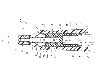
As
shown, septum 40 can included a reinforced portion 100 on its proximal end
102.
Reinforced portion 100 can assist to prevent septum collapse during septum
activation. In general, reinforced portion 100 can include a sidewall 104
having an
increased thickness over the remaining sidewalls 106 of septum 40. Reinforced
portion 100 can include a thickness of between about 25% to 150% thicker than
the
remaining sidewalls 106 of septum 40. As shown in Figure 6, reinforced portion
100
can bulge outwardly from septum 40. Figure 7 shows an embodiment of a septum
40
having a reinforced portion 110 that bulges inwardly.
[0068] Figure 7 further shows an example of a septum 40 having a barrier
member
42 disposed on a proximal end 112 of septum 40. In this configuration, septum
40
does not include a distal cavity (e.g., distal cavity 48 of Figures 1 and 3-
6). Rather, in
such embodiments, septum 40 is retained against probe 54 of septum activator
40
instead of residing within the septum's distal cavity.
-Page 17-
CA 02881451 2015-02-06
WO 2014/031774 PCT/US2013/056034
[0069] The present invention may be embodied in other specific forms
without
departing from its structures, methods, or other essential characteristics as
broadly
described herein and claimed hereinafter. The described embodiments are to be
considered in all respects only as illustrative, and not restrictive. The
scope of the
invention is, therefore, indicated by the appended claims, rather than by the
foregoing
description. All changes that come within the meaning and range of equivalency
of
the claims are to be embraced within their scope.
-Page 18-