Note: Descriptions are shown in the official language in which they were submitted.
CA 02881692 2015-02-10
WO 2014/026698 PCT/EP2012/003461
1
METHOD AND SYSTEM FOR SUBMERGED ARC WELDING
TECHNICAL FIELD
The invention relates to a method for submerged arc welding according to the
preamble
of claim 1 and a submerged arc welding system according to the preamble of
claim 13.
BACKGROUND OF THE INVENTION
Submerged arc welding (SAW) is a welding method characterized by high
productivity
and quality, often used for longer welding seams in thicker materials.
It is well known to use a consumable electrode to conduct a weld current
through a work
piece. The weld current forms an arc between the consumable electrode and the
work
piece to create a weld puddle on the work piece. This consumable electrode is
known
as a hot wire.
Submerged arc welding is characterized in that the melted material and the
arcs are
protected beneath a layer of pulverized flux. The flux melts in part during
the process,
thus creating a protecting layer of slag on the weld puddle. The electrical
current used in
the process is relatively high, usually within 300-1500 Ampere per electrode.
The
electrodes used in submerged arc welding are usually 2.5 ¨ 6 mm in diameter.
Fluxes used in submerged arc welding are granular fusible minerals typically
containing
oxides of manganese, silicon, titanium, aluminium, calcium, zirconium,
magnesium and
other compounds such as calcium fluoride. The flux is specially formulated to
be
compatible with a given electrode wire type so that the combination of flux
and wire
yields desired mechanical properties. All fluxes react with the weld puddle to
produce
the weld metal chemical composition and mechanical properties. It is common
practice
to refer to fluxes as 'active' if they add manganese and silicon to the weld.
The amount
of manganese and silicon added is influenced by the arc voltage and the
welding
current level.
CA 02881692 2015-02-10
WO 2014/026698 PCT/EP2012/003461
2
It is desirable to increase the productivity of a SAW process. This can be
done by
increasing the weld speed and the deposition rate, i.e. the rate at which weld
metal is
actually deposited onto the work piece surface. The heat input should be kept
on a level
that preserves the mechanical properties of the welded parent material and the
weld
should have mechanical properties of a certain level.
Heat input can be calculated as follows:
/xUx60 _3 (1),
Q = risAw _______________________________ 0
v
Where Q (kJ/mm) is heat input, nsAw is an efficiency factor, I (A) is welding
current, U
(V) is arc voltage and v (mm/min) is welding speed.
One way to increase the deposition rate is to use multiple hot wires in a
single weld
puddle. Usually 2-3 hot wires are used, however, usage of up to 6 hot wires is
known.
Using more than one hot wire in a single weld puddle enables increased
deposition
rates and therefore improves economy of welding. It also enables improved weld
quality
due to the possibility of assigning the leading and trailing hot wires with
different tasks.
The hot wires can be arranged in various settings or formations. For instance,
the hot
wires can be positioned shifted out in a transverse direction with respect to
a welding
direction or be positioned at a distance from each other in the welding
direction, or a
combination thereof. In the event two or more hot wires are shifted out in the
transverse
direction, they may be positioned side by side. This is used for surface
welding or
specific joints where a wide joint is needed. Side by side welding leads to
lower
penetration and more width.
Alternatively, the hot wires are positioned at a distance from each other in
the welding
direction. A hot wire located first in the direction of welding is normally
referred to as a
leading hot wire and a hot wire located behind the leading hot wire is
normally referred
to as a trailing hot wire. Normally, the leading hot wire and the trailing hot
wires serve
CA 02881692 2015-02-10
WO 2014/026698 PCT/EP2012/003461
3
different roles in the welding process. It is for instance known to control
the leading hot
wire such that a desired degree of penetration is obtained whereas the
trailing hot wire
controls weld bead appearance, contour and fill.
It is also possible to separate the hot wires far from one another, in which
case the weld
puddle generated by the leading hot wire may solidify before a second hot wire
has
reached the puddle. In this event, the two hot wires more or less perform the
task of two
consecutive welding passes.
Another way to improve the deposition rate is to add one or more consumable
electrodes that melt without formation of arcs. These electrodes are called
cold wires. A
cold wire is continuously fed towards a molten weld puddle in close proximity
to one or
more hot wires, where the cold wire is melted by heat generated by said hot
wires. A
current may be applied to a cold wire for heating thereof.
It is known from, for example, WO 2012/041375 Al to manipulate the cold wire
feed
speed independently from the hot wire feed speed. It is also known from JP
2205267 to
control the feed speed of a filler wire in dependence on the shape of the
groove to
maintain a certain melt pool length.
The introduction of cold wire material into the weld puddle may lead to
improved control
of the composition of the weld alloy, which may lead to improved welds. It is
preferable
to introduce the cold wire in the vicinity of and preferably into an arc
generated by a hot
wire (even more preferably in the vicinity of or into arcs generated by a
plurality of hot
wires). Furthermore, feeding of cold wire material into the weld puddle may
lead to an
increase of productivity of up to 100% with optimized welding parameters. In
other
words, a cold wire allows for higher deposition rates without increasing the
heat input.
A problem associated with cold wires is that they sometimes increase the
welding
process instability when the cold wire is not melted at an even pace, or
strike the parent
material through the melt pool. This can cause weld defects and inclusions in
the weld
metal of unmelted cold wire material.
CA 02881692 2015-02-10
WO 2014/026698 PCT/EP2012/003461
4
A first object of the invention is to provide a method for submerged arc
welding using at
least one cold wire, which method ensures a stable welding process and
improved weld
quality.
A second object of the invention is to provide a submerged arc welding system
adapted
to use at least one cold wire, which system ensures a stable welding process
and
improved weld quality.
BRIEF DESCRIPTION OF THE INVENTION
A hot wire is a consumable electrode connected to a power source to maintain
an arc
between said consumable electrode and a work piece.
A cold wire is a consumable electrode that melts without formation of an arc.
A cold wire
can be connected to a power source for heating of the cold wire; however, the
current
transferred through the cold wire will not generate an arc.
A welding parameter is a welding equipment parameter that has a direct
influence on
the welding process. Examples of welding parameters are welding current, arc
voltage,
welding speed, hot wire feed speed and cold wire feed speed. The term welding
parameter does not cover parameters not directly related to the welding
equipment,
even if said parameters do influence the welding process. Examples of such
parameters
not included in the term welding parameters are the shape and composition of
the
object to be welded.
Some welding parameters are related to one or more hot wires. One example of a
welding parameter related to a hot wire is a hot wire welding parameter. A hot
wire
welding parameter (e.g. welding current, arc voltage, hot wire feed speed and
welding
speed) has a direct influence on the behavior of an arc generated by said hot
wire.
Another example of a welding parameter related to a hot wire is a welding
parameter
that exerts influence on and/or is influenced by a hot wire welding parameter.
These
CA 02881692 2015-02-10
WO 2014/026698 PCT/EP2012/003461
parameters (e.g. motor speed of a hot wire feeding motor) may have an indirect
influence on the behavior of an arc generated by said hot wire.
As mentioned above, a welding parameter may be related to more than one hot
wire.
For example, when two or more hot wires are connected to the same power
source, it
may be sufficient to measure one or more welding parameters related to one of
said hot
wires and assume that the measured parameter values apply to all hot wires.
A parameter related to another parameter is a parameter that, directly or
indirectly, is
influenced by and/or exerts an influence on said other parameter.
An active welding parameter is a welding parameter that is adjusted during
welding in
response to changes in welding conditions (e.g. changes in the distance
between the
end of the hot wire and the work piece). Active welding parameters are
sometimes
adjusted to maintain one or more non-active welding parameters at an
essentially
constant level. Active welding parameters may be adjusted manually or
automatically in
response to detected welding condition variations. Active welding parameters
may also
be related to and adjusted through adjustment of other active welding
parameters. An
active welding parameter as defined herein may also be referred to as a
variable
welding parameter, in contrast to welding parameters that are intended to be
maintained
at an essentially constant level.
An active welding parameter, e.g. welding speed, can be related to more than
one hot
wire.
A welding direction is defined as the direction in which a weld is intended to
run. An
alternative definition of the welding direction is the direction of movement
of a welding
head or a hot wire.
Welding conditions are external factors that influence the welding process.
Examples of
external factors are the shape of the work piece surface and material
properties of the
work piece.
CA 02881692 2015-02-10
WO 2014/026698 PCT/EP2012/003461
6
A variable feed speed is a feed speed that can assume more than one value
above zero
and can be adjusted from one of said values to the other of said values during
welding.
Continuous measurement of an active welding parameter means that active
parameter
values are measured at constant or varying intervals. Normally, welding
parameters are
measured at intervals of about 1 ms. These measured values are filtered for
more
accurate results and the (filtered) active welding parameter values, which are
used to
determine suitable cold wire feed speed target values, are obtained at
intervals having a
length (in average) of between 0-1000 ms, preferably 50-250 ms and most
preferably
75-125 ms.
The method and system according to the invention are intended for use during
welding
and not during start-up or termination of the welding process. The phase
between the
start-up phase (creation of the arc and stabilization of welding parameters)
and the stop
phase (termination of the welding process) will hereinafter be referred to as
the welding
phase. The welding phase is a phase during which welding action is carried
out.
The first object of the invention is achieved with a method for submerged arc
welding as
defined by independent claim 1.
The method for submerged arc welding comprises the step of guiding a first hot
wire
electrode towards a work piece and transferring current to said first hot wire
for arc
generation, e.g. to generate an arc between the first hot wire and the work
piece, to
create a weld puddle. The method further comprises the step of guiding a cold
wire at a
variable feed speed towards said weld puddle. The method also comprises the
steps of
continuously measuring, during a welding phase, at least a first active
welding
parameter related to at least said first hot wire, which first active welding
parameter is
continuously adapted to existing welding conditions, and adjusting the cold
wire feed
speed in dependence on at least first active welding parameter variations, to
maintain
high welding stability and high weld quality.
CA 02881692 2015-02-10
WO 2014/026698 PCT/EP2012/003461
7
The first active welding parameter is continuously measured during the welding
phase.
Continuous measurement of an active welding parameter means that the active
welding
parameter is measured at certain intervals, usually about 1 milliseconds (ms)
long. The
cold wire feed speed may be adjusted in dependence on filtered first active
welding
parameter values, measured at intervals having an average length of 0-1000 ms,
preferable 50-250 ms and most preferably 72-125 ms. The cold wire feed speed
may
also be adjusted in dependence on unfiltered first active welding parameter
values.
The first active welding parameter may be an active hot wire welding
parameter, i.e. an
active welding parameter that has a direct influence on an arc generated by
said hot
wire. The first active welding parameter may also be related to one or more
active hot
wire welding parameters.
The first active welding parameter may be related to more than one hot wire.
The first
active welding parameter may for example be related to two hot wires connected
to a
single power source.
Active welding parameter values are used to determine corresponding target
values for
the cold wire feed speed. A target value for the cold wire feed speed may be
determined
in dependence on more than one active welding parameter value, which values
relate to
different active welding parameters. A target value may also be determined in
dependence on a corresponding, single active welding parameter value. It is
also
possible to determine a target value for the cold wire feed speed in
dependence on a
plurality of active welding parameters values related to a single active
welding
parameter.
When a welding process becomes unstable, a non-adaptive control of the cold
wire feed
speed may result in cold wire feed speeds unsuitable for the current welding
conditions
and increased welding process instability. The cold wire may not melt before
it comes
into contact with the bottom of the weld puddle if the cold wire feed speed is
too high,
and a cold wire feed speed that is too low may result in insufficient
deposition rates.
CA 02881692 2015-02-10
WO 2014/026698 PCT/EP2012/003461
8
This may lead to deposition rate variations, weld defects and inclusions in
the weld
metal of unmelted cold wire.
These problems are avoided when the cold wire feed speed is made dependent on
one
or more active welding parameters, which are adjusted to better suit the
current welding
conditions. The cold wire feed speed is adjusted during welding to the current
welding
conditions and the active hot wire welding parameters. This will improve the
quality of
the weld and the welding process stability.
Adjustment of the cold wire feed speed is preferably but not necessarily
carried out
automatically in response to active welding parameter variations, to ensure a
quick and
precise response to a change in welding conditions.
It is known to adjust at least one active welding parameter to maintain one or
more
welding parameters at a set level also when disturbances, such as stick out
variations
caused by work piece surface irregularities, variations in the welding process
or joint
configurations, are encountered.
An active welding parameter may be related to and adjusted through adjustment
of
another active welding parameter, and the cold wire feed speed can be adjusted
in
dependence on any of these active welding parameters. For example, adjustment
of the
feed speed of a hot wire may change the arc voltage of that hot wire. The cold
wire feed
speed can be adjusted in dependence on any one or both of said parameters.
Maintaining a welding parameter at a set or constant level means that the
welding
parameter is restored, through adjustment of at least one active welding
parameter, to
said set level if it should diverge from said set level, e.g. as a consequence
of an
encountered disturbance. That is, the active welding parameter is adjusted to
restore
said welding parameter to a specific level when the welding parameter assumes
a value
that differs from said level.
CA 02881692 2015-02-10
WO 2014/026698 PCT/EP2012/003461
9
A constant wire feed (CW) process is a welding process during which the hot
wire feed
speed is set at a specific rate and the welding current is automatically
adjusted to
maintain an arc voltage level.
The method according to the invention may comprise the step of adjusting the
cold wire
feed speed in dependence on welding current variations, when the welding
current is an
active hot wire welding parameter. This embodiment makes the method compatible
with
CW welding processes.
A constant amperage (CA) process is a process wherein an arc voltage level is
maintained essentially constant and the welding current is controlled through
adjustment of the hot wire feed speed. A hot wire feed speed increase will
result in a
welding current increase, since the welding current level is related to the
distance
between the electrode end and the work piece. Similarly, a hot wire feed speed
reduction will result in a welding current reduction. Consequently, the
amperage level
can be maintained essentially constant through adjustment of the hot wire feed
speed.
The method according to the invention may comprise the step of adjusting the
cold wire
feed speed in dependence on hot wire feed speed variations, when the hot wire
feed
speed is an active hot wire welding parameter. This embodiment makes the
method
compatible with CA welding processes.
In constant current (CC) processes, the welding current remains essentially
constant
whereas the arc voltage is dependent on the rate at which the hot wire is fed
towards
the work piece.
The method according to the invention advantageously involves the step of
adjusting
the cold wire feed speed in dependence on changes in hot wire feed speed
and/or arc
voltage when the hot wire feed speed and/or the arc voltage are active hot
wire welding
parameters. This embodiment makes the method compatible with CC welding
processes.
_
CA 02881692 2015-02-10
WO 2014/026698 PCT/EP2012/003461
It is possible to link the cold wire feed speed to other active welding
parameters not
mentioned in the specification, on the condition that these parameters are
adaptable to
changing welding conditions and are related to at least one hot wire
electrode.
The cold wire feed speed can also be dependent on the welding power. The
welding
power can be defined as:
P=Ux1 (2),
where P (kJ) is welding power, U (V) is arc voltage and I (A) is welding
current. Less
energy in the welding process means that there is less excessive energy to
melt the
cold wire. Advantageously, the cold wire feed speed is reduced when there is
less
energy in the welding process. More energy means that there is more excessive
energy
to melt the cold wire, and so the cold wire feed speed is advantageously
increased in
response to a detected increase in welding power.
The welding power may constitute an active welding parameter. It is also
possible to
define the welding power as a parameter related to one or more active welding
parameters, e.g. arc voltage and/or welding current.
In some embodiments, the cold wire feed speed is dependent on a plurality of
active
welding parameters related to the same hot wire. This is, for example, the
case when
the welding power is dependent on an arc voltage and a welding current that
change
over time (equation 2). It is also possible to maintain one of the arc voltage
and the
welding current essentially constant over time.
The cold wire feed speed can also be dependent on the heat input. The heat
input can
be defined as:
Q = k -u-L-: x 10-3 (3),
where Q (kJ/mm) is the heat input, k (dimensionless) is the thermal
efficiency, U (V) is
voltage, I (A) is current and v (mm/min) is the welding speed. Here, the
welding speed
CA 02881692 2015-02-10
WO 2014/026698 PCT/EP2012/003461
11
may also be an active welding parameter. The welding speed can be defined as
the
speed at which a welding head or one or more hot wires are moved across a work
piece
surface.
As above, the heat input can be defined as a variable parameter, related to
one or more
active welding parameters, to be used to determine cold wire feed speed
values. The
heat input can also be defined as an active welding parameter.
Sometimes it is desirable to maintain the welding energy at an essentially
constant level
throughout the welding process and vary the amount of electrode material that
is
deposited on the work piece. In this case, an increase in the hot wire feed
speed will
result in an increase in the cold wire feed speed, and correspondingly, a
reduction of the
hot wire feed speed will result in a reduced cold wire feed speed.
There may be alternative definitions of the welding power or heat input and
any
definition is applicable in the present invention.
In one embodiment, the method advantageously comprises and repeats the steps
of
determining a target value for the cold wire feed speed based on at least a
first active
parameter value and adjusting said cold wire feed speed to said target value.
Advantageously, the arc has stabilized before the cold wire feed speed reaches
a target
value higher than its previously measured target value, to ensure that the
cold wire does
not hit the bottom of the weld puddle. For example, the arc may become
unstable
following an increase of the hot wire feed speed.
One way of ensuring that the cold wire feed speed is not increased too much,
too soon,
is to increase the cold wire feed speed in steps until the cold wire has
reached its target
value. The cold wire feed speed is advantageously increased in steps of up to
100
cm/min, advantageously 1-10 cm/min and even more advantageously 4-6 cm/min.
The
cold wire feed speed is not increased as quickly as the corresponding active
welding
CA 02881692 2015-02-10
WO 2014/026698 PCT/EP2012/003461
12
parameter(s), thus providing sufficient time for the arc to stabilize and melt
the end of
the cold wire before the cold wire hits the bottom of the weld puddle.
The time interval between active welding parameter measurements is
advantageously
as short as possible. A suitable time interval is about 1 ms. The measured
values may
be filtered to achieve a more accurate adjustment of the cold wire feed speed.
Active welding parameter values (filtered or unfiltered) used to determine
target values
for the cold wire feed speed are advantageously measured at intervals having a
mean
length of 10-1000 ms, preferably 50-500 ms and most preferably 75-125 ms.
Consequently, the cold wire feed speed may be adjusted in steps having a mean
length
of 10-1000 ms, advantageously 50-500 ms and most preferably 75-125 ms. It is
of
course possible to increase the time interval between the measurements of the
active
welding parameter to up to 1000 ms.
The initiation of the increase of the cold wire feed speed can be delayed with
respect to
the occurrence of the active welding parameter value(s) on basis of which the
target
value for the cold wire feed speed has been determined. The increase may then
be
carried out continuously or in one or more steps, as described above. The
length of said
time delay can, for example, be dependent on the size of said cold wire feed
speed
increase, i.e. the difference between the target value and the previous target
value, or
on the size of said increase in said active hot wire welding parameter.
The length of said delay may be 0-10 seconds and most preferably 0.5-3 seconds
per
1000 mm/min increase in hot wire feed speed or per 100A increase. The delay in
time
can also be set constant at 0-10 seconds, most preferably 0.5-3 seconds,
regardless of
the size of the increase. The time delay can be defined as the time period
between the
occurrence of an active welding parameter value and the initiation of a cold
wire feed
speed increase caused by said active welding parameter value.
CA 02881692 2015-02-10
WO 2014/026698 PCT/EP2012/003461
13
The cold wire feed speed is usually below 120% of the hot wire feed speed, and
advantageously between 60-80% of the hot wire feed speed. A hot wire feed
speed can
assume any value from 1000 mm/min to 10000 mm/min.
Should the hot wire parameter change again before the cold wire feed speed has
reached its target value, then another target value for the cold wire feed
speed is
determined and the cold wire feed speed is adjusted accordingly.
A reduction of the cold wire feed speed is advantageously carried out
instantaneously
with respect to the detection of the active welding parameter value(s) causing
said
reduction, and in a single step. Examples of hot wire parameter variations
causing a
reduction of the cold wire feed speed are: reduction of the hot wire feed
speed, welding
current, arc voltage or welding energy. An instantaneous reduction of the cold
wire feed
speed ensures that the cold wire will melt before it hits the bottom of the
weld puddle
even if the melting rate is reduced. The time delay should be as short as
possible.
Advantageously, the target value for the cold wire feed speed is reached
within 200 ms,
preferably within 100 ms, more preferably within 10 ms and most preferably
within 1 ms
with respect to the occurrence of the corresponding active welding parameter
value
causing said reduction.
It is possible to reduce the cold wire feed speed to a level below the target
value, to
ensure that the arc is given sufficient time to stabilize and that the cold
wire does not hit
the bottom of the weld puddle, and then increase the cold wire feed speed (as
described above with reference to an increase of the cold wire feed speed)
until the
target value is reached. The cold wire feed speed may even be brought to a
halt before
being increased to said target value.
The cold wire feed speed can be increased or reduced in one or more steps. It
is also
possible to adjust the cold wire feed speed continuously according to a curve
having a
constant or changing gradient. The gradient may increase when the cold wire
feed
speed approaches its target value, remain constant throughout said adjustment
of the
CA 02881692 2015-02-10
WO 2014/026698 PCT/EP2012/003461
14
cold wire feed speed or decrease when the cold wire feed speed reaches its
target
value.
The cold wire feed speed may be adjusted in steps and the steps may have
varying
length (ms) and/or height (cm/min). For example, the steps may be shorter and
higher
when the cold wire approaches its target value, or, alternatively, be shorter
and higher
when the cold wire feed speed adjustment is initiated. Of course, the
adjustments of the
cold wire feed speed may also be carried out in steps having a constant length
(ms)
and/or a constant height (cm/min).
An active welding parameter change detected during adjustment of the cold wire
feed
speed will result in a new target value being set for the cold wire feed
speed. The new
target value is applied immediately, i.e. the control unit immediately
instructs the cold
wire feeding means to adjust the cold wire feed speed to the new target value
in
accordance with any method described herein (which may or may not include a
time
delay).
A cold wire feed speed increase is preferably delayed with respect to the
occurrence of
an active welding parameter value causing said increase, and a reduction of
the cold
wire feed speed is preferably instantaneous or delayed with as short a time
period as
possible with respect to an active welding parameter value causing said
reduction.
The method may comprise the steps of guiding more than one hot wire towards
the
work piece and controlling the cold wire feed speed in dependence on a
plurality of
active welding parameters related to one or more of said hot wires. This
ensures
accurate control of the cold wire feed speed.
The cold wire feed speed may be controlled in dependence on all hot wires in
an arc
welding system or in dependence on a subset of hot wires, said subset
comprising one
or more hot wires.
CA 02881692 2015-02-10
WO 2014/026698 PCT/EP2012/003461
The cold wire feed speed may be controlled in dependence on active welding
parameters of the same type or active welding parameters of more than one
type.
The cold wire feed speed may be controlled in dependence on a mean value for a
plurality of active welding parameters of the same type or a weighted mean
value for a
plurality of active welding parameters of the same type. Both solutions ensure
improved
control of the cold wire feed speed; the latter solution when it is desirable
to strengthen
the cold wire feed speeds dependence on a particular subset of active welding
parameters, e.g. active welding parameters related to one or more hot wires
located in
the vicinity of said cold wire or one or more hot wires performing a specific
task.
It is possible to alternate between active welding parameters when determining
target
values for the cold wire feed speed.
It may be advantageous to alternate between hot wires when determining target
values
for the cold wire feed speed. This may, for example, ensure a more accurate
adjustment
of the cold wire feed speed when a plurality of hot wires alternately produce
an arc
between themselves and the work piece, in which case the cold wire feed speed
may
always be controlled in dependence on a hot wire currently producing an arc
between
itself and the work piece.
It is also advantageous to alternate between hot wires when one or more of the
hot
wires switches from DC to AC during welding. For example, a tandem welding
process
may involve a leading welding head provided with direct current (DC) (to
control degree
of penetration) and a trailing welding head provided with alternating current
(AC) (to
control weld bead appearance, contour and fill), wherein the leading welding
head
switches to AC during a second pass. In this case, it may be advantageous to
link the
cold wire feed speed to the trailing electrode during a first pass and to the
leading
and/or the trailing electrode during a second pass, considering that an AC
electrode can
be used to control weld bead appearance and fill. Alternatively, it may be
advantageous
to have the cold wire feed speed dependent on the leading electrode during the
first
pass, considering that a DC electrode generates a more stable arc.
CA 02881692 2015-02-10
WO 2014/026698 PCT/EP2012/003461
16
Obviously, the method may include the step of measuring active hot wire
welding
parameters of different types. It is also possible to use one or more active
welding
parameters related to the same hot wire(s) when determining the target value
for the
cold wire feed speed.
The method advantageously comprises the step of guiding at least a second
consumable hot wire electrode towards the work piece and transferring current
to said
second hot wire for arc generation, e.g. to generate an arc between the second
hot wire
and the work piece. The first and the second hot wires are arranged to create
a
common weld puddle. Of course, it is possible to use more than two hot wires
for
creation of a single weld puddle. The method may further include the steps of
continuously measuring, during a welding phase, at least a second active
welding
parameter related to at least said second hot wire, which second active
welding
parameter is continuously adapted to existing welding conditions, and
adjusting the cold
wire feed speed in dependence on variations in at least said first and second
active
welding parameters, to maintain a high welding stability and high weld
quality.
The second active welding parameter may be an active hot wire welding
parameter or
an active welding parameter related to an active hot wire welding parameter.
Using more than one hot wire increases the productivity of the SAW process and
using
active welding parameters of both hot wires to control the cold wire feed
speed ensures
improved control over the cold wire feed speed adjustment process.
A plurality of hot wires can be mounted in various formations. When the hot
wires are
arranged at a distance from one another along the welding direction, the front
hot wire is
referred to as the leading hot wire and the one or more hot wires following
the leading
hot wire are referred to as trailing hot wires.
Advantageously, the cold wire is located in parallel with and in the
overlapping region
between hot wires. This will ensure that the variation of the magnitude of the
CA 02881692 2015-02-10
WO 2014/026698 PCT/EP2012/003461
17
overlapping region will be reduced and the variation of the deposition rate of
the cold
wire will likewise be reduced.
Optionally, the hot wires lie in a first plane and the cold wire lies in a
second plane
orthogonal to the first plane. This enables a symmetric position of the cold
wire in
relation to the first and second hot wires. A symmetric positioning of the
cold wire with
respect to the hot wires allows for more stable arc plasma conditions at the
location of
the cold wire. Thus a more stable deposition rate of the cold wire can be
achieved.
The active welding parameter can be related to the leading and/or one or more
of the
trailing hot wires.
Each hot wire can be powered via a separate power source. This may be
advantageous
in many applications since the control of power supply to each hot wire is
facilitated.
The magnet interference between hot wires may also be reduced by supplying
phase
shifted welding currents to the hot wires. This may be accomplished by
conventional
Scott coupled power sources or by use of complex power sources, such as high
frequency converters, for instance.
Welding apparatuses using two or more separate power sources tend to be
expensive
and bulky. Hence, for some applications, such as welding in constrained
spaces, it may
be desirable to use a single power source for feeding a welding current to the
hot wires.
An advantage of using more than one hot wire is that the deposition rate may
be
increased for a given amount of power input. The use of more than one hot wire
allows
for a reduction in electrode diameter, which in turn increases the current
density for
each hot wire. The increased current density allows for increased pre-heating
of the
electrode, hence a higher deposition rate can be maintained at less heat
transfer to the
weld puddle.
As mentioned above, leading and trailing hot wires may serve different
purposes. The
leading hot wire is advantageously connected to a DC power source, which
ensures
CA 02881692 2015-02-10
WO 2014/026698 PCT/EP2012/003461
18
high power and high penetration, whereas trailing hot wires usually are
connected to AC
power sources and provides more deposited material at a low current. The
leading hot
wire is usually more stable. Similarly, hot wires received in a leading
welding head may
be connected to single DC power source whereas hot wires received in a
trailing
welding head may be connected to a single AC power source.
The method according to the invention may comprise the step of measuring
active
welding parameters related to said leading hot wire and at least one trailing
hot wire.
It is possible to use more than one cold wire in the welding process. The feed
speed of
each cold wire can be independently determined. This is advantageous when the
cold
wires are exposed to different amounts of heat and subject to different
welding
conditions. It is also possible to apply the same welding speed, determined
through
measurement of one or more active welding parameters, on a plurality of cold
wires.
This makes it possible to reduce the complexity of the welding apparatus (for
example,
it becomes possible to feed more than one cold wire by means of a single cold
wire
feeding means).
The second object of the invention is achieved with a submerged arc welding
system for
carrying out the method according to the invention. The submerged arc welding
system
comprises hot wire feeding means for feeding a first hot wire towards a work
piece and
first contact means for transferring current to said first hot wire for arc
generation, e.g. to
generate an arc between the first hot wire and the work piece, to generate a
weld
puddle. The system further comprises second wire feeding means for feeding a
cold
wire at a variable cold wire feed speed towards said weld puddle and a control
unit for
controlling the second wire feeding means. Additionally, the system comprises
measuring means adapted to continuously measure, during a welding phase, at
least a
first active welding parameter related to at least said first hot wire, which
first active
welding parameter is continuously adapted to existing welding conditions, and
provide
information to said control unit regarding first active welding parameter
values. Said
control unit is adapted to determine targets value for the cold wire feed
speed based on
said information, each target value determined in dependence on at least a
first active
CA 02881692 2015-02-10
WO 2014/026698 PCT/EP2012/003461
19
welding parameter value, and to control said second wire feeding means to
adjust said
cold wire feed speed to said target values.
The system according to the invention ensures that the cold wire feed speed is
adapted
to one or more active welding parameters of one or more hot wires and does not
become too high or too low during the welding process. This will ensure a high
quality
weld and a stable welding process.
A contact means can be any suitable means for transferring a welding current
to a hot
wire. The contact means is suitably adapted to guide the hot wire towards the
work
piece. An example of a suitable contact means is a contact tube adapted to
receive a
hot wire, which contact tube is connected to a power source.
The hot wire feeding means and the cold wire feeding means are arranged so
that they
can provide different wire feed speeds. However, they may form part of a
single wire
feeding unit. They may also be arranged separately from one another.
Measuring means according to the invention are adapted to continuously measure
active welding parameter values and provide information regarding said values
to said
control unit. An active welding parameter related to a hot wire may be an
active hot wire
welding parameter or an active welding parameter related to an active hot wire
welding
parameter. The term active hot wire welding parameter covers, for example, hot
wire
feed speed, welding current and arc voltage.
Information relating to a specific active welding parameter value is
advantageously sent
from the measuring means to the control unit as soon as the value is measured,
to
prevent unnecessary delays in the adjustment of the cold wire feed speed.
Said measuring means may comprise a sensor adapted to measure the rotational
speed of a motor shaft in a motor arranged to feed a hot wire towards a work
piece.
Said measuring means may also comprise a sensor for measuring the diameter of
a hot
wire coil rotated by means of said motor shaft for feeding said hot wire
towards said
CA 02881692 2015-02-10
WO 2014/026698 PCT/EP2012/003461
work piece. It is also possible to calculate or use an estimated value of the
diameter of
the hot wire coil. This information is transferred to said control unit, which
calculates the
hot wire feed speed. These solutions are simple and less expensive.
It is also possible to use one or more sensors that measure the feed speed of
the hot
wire. This solution provides more accurate results.
Said measuring means may also comprise one or more shunts in the power source,
for
measuring the welding current. The shunt is placed in series with a load so
that all of
the current to be measured will flow through it. The voltage drop across the
shunt is
proportional to the current flowing through it and the shunts resistance is
known,
wherefore measuring the voltage allows for determination of the welding
current.
Said measuring means may also comprise one or more means for measuring arc
voltage. Arc voltage is advantageously measured between the work piece and the
closest end of the hot wire to avoid voltage drop.
A control unit according to the invention is any means capable of determining
a target
value for a cold wire feed speed based on information relating to at least one
active
welding parameter. The control unit is arranged to receive information from
one or more
measuring means and based on said information register, determine or calculate
an
active welding parameter value. Obviously, said control unit and said
measuring means
may form part of a single control means. A control means may for example
comprise a
control unit and at least one sensor for registering a hot wire feed speed. A
control
means may also comprise a circuit arrangement for determining arc voltage.
Said
control unit and said measuring means may also be separate from one another.
An active welding parameter does not have to be measured at a corresponding
hot
wire. For example, a weld current can be measured at a power source connected
to the
hot wire.
_
CA 02881692 2015-02-10
WO 2014/026698 PCT/EP2012/003461
21
The control unit and the cold wire feeding means can form part of a single
unit or be
separate entities.
The control unit is arranged to determine target values for the cold wire feed
speed and
control the cold wire feeding means to implement said target values. The
control unit
may also be adapted to determine a suitable time delay for the initiation of
an
adjustment of the cold wire feed speed. The control unit may also be adapted
to
determine suitable lengths and heights for cold wire feed speed adjustment
steps and
gradients for cold wire feed speed adjustment curves. Information regarding
these
adjustments can be provided to the cold wire feed means in the form of
signals.
A plurality of parameters can be used as active welding parameters. Examples
of
suitable active welding parameters are hot wire amperage, arc voltage, welding
current
and welding energy. This makes the system and method compatible with a
plurality of
different welding processes (CA, CW, CC etc.). Alternative active welding
parameters
are hot wire heat input and hot wire welding power. Heat input and welding
power can
also be calculated based on information relating to one or more active welding
parameters.
The system is arranged to ensure that the cold wire feed speed does not rise
too quickly
following the occurrence of an active welding parameter value indicating that
the cold
wire feed speed should be increased. That is, the system ensures that the cold
wire
feed speed does not reach its target value until the arc is stabilized. The
initiation of the
cold wire feed speed increase may be delayed or the increase may be performed
at an
average rate slower than the average change rate of the active parameter
value. It is of
course possible to combine these two alternatives.
The cold wire feed speed may be increased in steps of up to 100 cm/min,
preferably
between 1-10 cm/min and most preferably between 4-6 cm/min, until it reaches
its
target value. It is possible to use smaller steps than 1 cm/min, for example
when the
difference between the target value and the present cold wire feed speed value
is less
than 1 cm/min.
CA 02881692 2015-02-10
WO 2014/026698 PCT/EP2012/003461
22
In some embodiments, the cold wire feed speed is adjusted only if the
difference
between the target value and the present cold wire feed speed exceeds a
predetermined value.
The steps are advantageously executed with intervals of between 10-1000 ms,
preferably between 50-500 ms and most preferably 75-125 ms until the cold wire
feed
speed reaches its target value.
An increase of the cold wire feed speed to a target value does not have to be
executed
in steps of the same height (cm/min) or at constant intervals (ms).
A reduction of the cold wire feed speed is advantageously carried out
instantaneously or
at least within 200 ms, advantageously within 100 ms, more advantageously
within 10
ms and most advantageously within 1 ms with respect to the occurrence of the
active
welding parameter value(s) causing said reduction. A quick reduction of the
cold wire
feed speed ensures that the cold wire will not hit the bottom of the weld
puddle before
the arc has stabilized.
The cold wire feed speed may be reduced to a level below the target value and
then
increased to the target value, to ensure that the arc is stable once the cold
wire feed
speed reaches its target value.
An increase or reduction of the cold wire feed speed may be executed in one or
more
steps. Alternatively, the adjustment of the cold wire feed speed may be
continuous. It is
also possible to use any combination of these two alternatives.
A system according to the invention may comprise at least one welding head
adapted to
receive at least one cold wire and at least one hot wire. Advantageously, the
welding
head is adapted to receive more than two wires, which makes the system more
cornpact.
CA 02881692 2015-02-10
WO 2014/026698 PCT/EP2012/003461
23
Alternatively, the system comprises at least one welding head adapted to
receive one or
more hot wires and means for feeding one or more cold wires towards the weld
puddle.
The system may comprise a single welding head arranged to receive a plurality
of cold
wires or a plurality of welding heads arranged to receive one or more cold
wires. The
hot and cold wires may be received in separate welding heads or wire feeding
units.
The submerged arc welding system can be arranged to feed the hot wires and
cold
wires towards the work piece at different locations relative one another and
in different
directions.
The system according to the invention advantageously comprises hot wire
feeding
means arranged to feed a second consumable hot wire electrode towards the work
piece and second contact means arranged to transfer a current to said second
hot wire
for arc generation, e.g. to generate an arc between the second hot wire and
the work
piece, wherein said first and second first and second contact means are
arranged to
transfer current for generation of a common weld puddle. The system may also
comprise measuring means arranged to continuously measure, during a welding
phase,
at least a second active welding parameter related to at least said second hot
wire,
which second active welding parameter is continuously adapted to existing
welding
conditions. Said measuring means provides information regarding measured
second
active welding parameter values to the control unit as soon as they are
measured. The
control unit is arranged to continuously determine target values for the cold
wire feed
speed based on information relating to said first and second active welding
parameters
and to control said second wire feeding means to adjust said cold wire feed
speed to
said target vales.
The hot wire feeding means for feeding the first hot wire can be separate from
the hot
wire feeding means for feeding the second hot wire. Alternatively, the hot
wire feeding
means for feeding the first and second hot wires may be one and the same.
CA 02881692 2015-02-10
WO 2014/026698 PCT/EP2012/003461
24
The control unit may receive a plurality of active welding parameter values
and weigh
the received values or calculate a mean value of some or all of said values,
using any
suitable approach, before determining the target value for the cold wire feed
speed.
Said first and second contact means may be connected to the same power source
or to
different power sources. In one embodiment, one of the power sources is an AC
power
source whereas the other power source is a DC power source.
The system according to the invention may of course be arranged to receive
more than
one cold wire. Additional cold wires may be separately controlled.
Alternatively, the
same target value for the cold wire feed speed can be applied to all or some
of the cold
wires. This may be suitable when one or more of the cold wires have the same
composition and dimensions. The same active welding parameter values can also
be
used to determine individual cold wire feed speeds for a plurality of cold
wires. The
individual feed speed of a cold wire may be determined in dependence on, for
example,
that cold wires composition and dimensions.
The control unit may employ any suitable function to determine a target value
for the
cold wire feed speed, wherein at least one variable is an active welding
parameter. It is
also possible to use predetermined tables or similar means wherein active
welding
parameter values corresponds to target values for the cold wire feed speed.
For
example, the control unit may be programmed to apply a cold wire feed speed
which is
60-80% of the hot wire feed speed.
The measuring means for measuring an active welding parameter related to said
second hot wire may be the same or separate from the measuring means for
measuring
an active welding parameter related to said first hot wire. A measuring means
according
to the invention may be arranged to measure one or more active welding
parameters
related to one or more hot wires.
A cold wire is advantageously introduced into an overlapping arc zone of more
than one
hot wire, to increase the deposition rate without having to increase the
welding current.
CA 02881692 2015-02-10
WO 2014/026698 PCT/EP2012/003461
It may be preferable to arrange the cold wire in between two hot wires. The
hot wires
may preferably be mounted at an axial distance being less than a cone diameter
of the
arc (normally it is assumed that the arc is present within a cone from the tip
of the hot
wire to the work piece and a normal opening angle is around 300, measured at
the
surface of the weld puddle). With this arrangement, the cold wire will be
introduced in
the outer parts of the arc area defined by the cone of both hot wires which
has shown to
be beneficial for the weld result.
Submerged arc welding can be operated as a fully-mechanised semi-automatic or
automatic process.
The scope of protection covers embodiments wherein a measuring means measures
active welding parameter values, the control means uses said measured values
to
determine other active welding parameter values (e.g. motor speed)
corresponding to
said measured values, and the control means uses said determined active
welding
parameter values to adjust an active welding parameter (e.g. motor speed) and
to
determine corresponding cold wire feed speed values.
BRIEF DESCRIPTION OF THE DRAWINGS
The present invention together with the above-mentioned and other objects and
advantages may best be understood from the following detailed description of
exemplary embodiments of the invention. The detailed description contains
references
to drawings, wherein:
Fig. la shows a twin wire welding apparatus according to the invention
connected
to a single power source;
Fig. lb shows an alternative embodiment of the welding apparatus in Fig.
la;
Fig. 2 shows an arc-welding welding head according to the invention;
Fig. 3 shows the welding head of Fig. 2 turned counter-clockwise by 90 ;
Fig. 4 shows a perspective view or the arc-welding head of Fig. 2;
CA 02881692 2015-02-10
WO 2014/026698 PCT/EP2012/003461
26
Fig. 5 shows a side view of an example embodiment of an arc-welding
welding
head
Fig. 6a-c show different arrangements of hot wires and cold wires;
Fig. 7a-c show different arrangements of two arc welding heads comprising
hot and
cold wires; and
Fig. 8a-8b graphically show possible relations between a cold wire feed speed
and a
variable active welding parameter.
DETAILED DESCRIPTION OF PREFERRED EMBODIMENTS OF THE INVENTION
In the drawings, equal or similar elements are referred to by equal reference
numerals.
The drawings are merely schematic representations, not intended to portray
specific
parameters of the invention. Moreover, the drawings are intended to depict
only typical
embodiments of the invention and therefore should not be considered as
limiting the
scope of the invention.
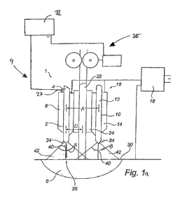
Figure 1a shows portions of a submerged arc welding system 9 comprising a twin
welding apparatus 1. The twin welding apparatus includes a first contact tube
2 for
guiding a first hot wire 4 towards a weld puddle 6. The first contact tube 2
is arranged in
a contact tip 8 in a conventional manner. Welding current is transferred
through said
contact tube 2 to the first hot wire 4. A second contact tube 10 is arranged
in the twin
wire welding apparatus 1 for guiding a second hot wire 12 towards the weld
puddle 6.
The second contact tube 10 is arranged in a contact tip 14 in a conventional
manner.
The first and second contact tips 8, 14 may be arranged in a single body,
which may be
aggregated by parts, or in separate bodies. At the second contact tube 10,
welding
current is transferred to the second hot wire 12.
A single power source 16 is connected to a contact device 18 including the
contact tips
8, 14 and housing the first and second contact tubes 2, 10. The single power
source 16
provides the same potential to the first and second hot wires 4, 12. The power
source
may be of any conventional type operable for twin wire welding, such as a
welding
converter, a welding transformer, a rectifier, a thyristor controlled
rectifier or an inverter.
CA 02881692 2015-02-10
WO 2014/026698 PCT/EP2012/003461
27
The twin wire welding apparatus 1 further includes a feeding arrangement for
feeding a
cold wire 22 into the weld puddle 6. The feeding arrangement includes a tube
24, which
is electrically insulated from the first and second contact tips 8, 14. The
cold wire 22 is
fed via the tube 24. When welding, arcs 40 will be present at the first and
second hot
wires 4, 12, but not at the cold wire 22. The cold wire 22 is melted by
introduction of the
cold wire into areas of the arcs 40. Suitably, the cold wire 22 is not
connected to any
electrical power source and will therefore generally assume a ground
potential.
However, it may be possible to connect the cold wire 22 to a power source for
pre-
heating the cold wire. However, the cold wire 22 will not be connected to a
power
source for the purpose of arc generation. The tube 24 may be a metallic tube
that is
isolated from the first and second contact tips 8, 14, or a ceramic tube.
In submerged arc welding an arc 40 is present between the tip of an electrode
and the
work piece. The arc and the melted material are protected beneath a layer of
pulverized
flux. The flux melts in part during the process, thus creating a protecting
layer of slag on
the weld puddle.
An arc 40 is shown in figure 1a. The contact of the arc 40 at the working
piece will be
moving in a random manner. However, normally it is assumed that the arc 40 is
present
within a cone 42 from a tip 34 of the hot wire to the weld puddle 6. The
opening angle 13
of the cone 42 may vary from welding case to welding case. However, a normal
opening
angle 13 is around 30 . For this reason it is preferable to locate the cold
wire 22 such that
it enters the arc area in an essentially orthogonal direction thereto at an
axial distance D
being less than L*cotan (13/2) from the consumable electrode measured at the
tip 34 of
the consumable electrode. Here L is the arc length, which is the distance from
the
electrode tip 34 to the closes point 36 of the weld puddle.
A flux hopper 11 (see figure 2) is arranged to feed granular flux to a contact
device 160
that holds the hot wires 4, 12 and the cold wire 22. The granular flux is fed
to the
contact device 160 via a nozzle (not shown).
CA 02881692 2015-02-10
WO 2014/026698 PCT/EP2012/003461
28
It may be preferable to arrange the cold wire 22 in between two hot wires 4,
12. The hot
wires 4, 12 are preferably mounted at an axial distance A being less than a
cone
diameter measured at the surface 30 of the weld puddle 6. With this
arrangement, the
cold wire 22 will be introduced into the outer parts of the arc area defined
by the cones
42 of both hot wires 4, 12, which is beneficial for the weld result.
The twin wire welding apparatus 1 further comprises a sensor 27 for measuring
the feed
speed of the first hot wire 4.
Of course, it is possible to employ more than one sensor and to measure the
feed
speed of both hot wires. However, in twin welding, when two hot wires are
connected to
the same power source, the hot wires are often considered as a single hot wire
and only
one sensor is required.
In alternative embodiments, the sensor 27 may be replaced by any suitable
measuring
means adapted to measure other active welding parameters, such as, for
example,
welding current or arc voltage.
The twin wire welding apparatus 1 in figure 1 is adapted to carry out a CA
welding
process. Disturbances, such as varying distance between the hot wire tips 34
and the
work piece, may have a negative effect on the welding process. Consequently,
the twin
wire welding apparatus 1 is adapted to adjust the feed speed of the hot wires
4, 10 to
maintain the amperage at an essentially constant level, to compensate for
disturbances.
The sensor 27 is arranged to continuously with intervals of about 1
millisecond measure
the hot wire 4 feed speed and transfer measured hot wire feed speed values to
a control
unit 31. The control unit 31 filters the received values; the values to be
subsequently
used to control the cold wire 22 feed speed are measured at intervals having a
mean
length of between 75-125 milliseconds. For each filtered value, the control
unit 31
determines a corresponding target value for the cold wire 22 feed speed.
CA 02881692 2015-02-10
WO 2014/026698 PCT/EP2012/003461
29
The control unit 31 also determines whether the target value is higher or
lower than the
current cold wire 22 feed speed. A reduction of the cold wire 22 feed speed is
advantageously carried out as quickly as possible, whereas an increase of the
cold wire
feed speed should be delayed with a time period dependent on the size of said
increase, to ensure that the arcs 40 are stabile before the cold wire 22 feed
speed
reaches its target value.
A signal is sent from the control unit 31 to a cold wire feeding means 35
(described in
detail below) disposed for feeding the cold wire 22 towards the work piece.
The cold
wire feeding means 35 increases or reduces the cold wire 22 feed speed in
accordance
with instructions from the control unit 31.
Figure lb shows an alternative embodiment of the welding apparatus 1 according
to
figure la, wherein the hot wires 4, 12 are connected to separate power sources
16, 17
and may be fed at different feed speeds.
The welding apparatus in figure lb can be programmed to run twice around a
steel tube
(not shown) to weld said steel tube to another steel tube. The first hot wire
4 is the
leading hot wire and the second hot wire 12 the trailing hot wire, as seen in
a welding
direction. The first hot wire 4 is connected to a first power source 16 and
the second hot
wire 12 to a second power source 17.
A second sensor 41 is arranged to measure the feed speed of the second hot
wire 12.
The second sensor 41 is connected to the control unit 31, which is arranged to
receive
information from both sensors 27, 41.
During the first lap, the first power source 16 transfers DC to the first hot
wire 4, which
ensures adequate penetration, whereas the second power source 17 provides the
second hot wire 12 with AC. Thus, the second hot wire 12 has a great influence
on weld
bead appearance, contour and fill. The first power source 16 switches from DC
to AC at
the beginning of the second lap, so that both hot wires 4, 12 will have a
great influence
on weld bead appearance, contour and fill during the second lap.
CA 02881692 2015-02-10
WO 2014/026698 PCT/EP2012/003461
The sensors 27, 41 are arranged to continually measure the feed speeds of the
hot
wires 4, 12 and provide information relating to the hot wire feed speeds to
the control
unit 31.
The control unit 31 is programmed to use hot wire 12 feed speed values
received from
the second sensor 41 to control the cold wire 22 feed speed during the first
lap, and to
use a mean value of the hot wire 4, 12 feed speed values received from the
first and
second sensors 27, 41 during the second lap. This ensures that the cold wire
22 feed
speed is linked to the feed speed of the hot wire(s) 4, 12 that has the
greatest influence
on the filling of the weld puddle 6.
Figures 2 to 4 depict different views of an electric arc-welding welding head
100 for the
twin welding apparatus 1 in the system 9 in figure 1a.
At one end, the welding head 100 comprises a contact device 160, which during
welding is in close proximity to the work piece to be welded. The contact
device 160
holds a wire assembly 170 comprising the wires 4, 22, 12 (only the cold wire
22 is
shown in figure 2). The wires 4, 22, 12 exit the contact device 160 through an
outlet
162 at the lower end of the contact device 160, which lower end faces the work
piece
during the welding operation. The wires 4, 22, 12 may be fed from respective
reservoirs
such as coils (not shown) towards the arc welding head 100.
As mentioned above, the wire assembly 170 comprises two hot wires 4, 12 and a
cold
wire 22 arranged in the contact device 160. The hot wires 4, 12 are arranged
as so
called twin wires, which are fed in parallel as a double wire arrangement.
Above the contact device 160 a feeder means 150 is arranged which feeds the
hot
wires 4, 12 towards the contact device 160. Typically, the feeder means 150
comprises
grooved wheels which move the hot wires 4, 12 towards the contact device 160.
The
feeder means 150 comprises an electrically insulating portion 156 for feeding
through
the cold wire 22. The electrically insulating portion 156 can consist of
feeder wheels with
CA 02881692 2015-02-10
WO 2014/026698 PCT/EP2012/003461
31
an extra insulated groove for the cold wire 22. The cold wire 22 can pass
through the
wire feeding means 150 freely. The feeder wheels are driven by a driving unit
152, e.g.
an electric motor.
The flux hopper 11 feeds granular flux to the contact device 160 via a nozzle
(not
shown).
Besides the driving unit 152 the wire feeding means 150 comprises a gear with
a drive
shaft. On the drive shaft of the gear a feeding wheel 154 (Fig. 5) is
arranged, which can
be pressurized by another wheel (not shown). The feeding wheel 154 drives the
wire
forward in the direction of the contact device 160.
Above the wire feeding means 150 a wire straightening unit 140 is arranged for
straightening the hot wires 4, 12. Two rollers depicted in a foremost position
of the wire
straightening unit 140 are used to exert a pressure on three fixed wheels
arranged
vertically one over the other in the rear part of the wire straightening
device. The
pressure the rollers are exerting on the wheels is adjustable via knobs at the
outside of
the wire straightening unit 140. The pressure of the rollers on the three
wheels is
straightening the wire. The wire straightening unit 140 comprises an
electrically
insulating portion 146 through which the cold wire 22 can pass freely through
the wire
straightening unit 140.
Above the wire straightening unit 140 a separate wire feeding means 35 is
disposed for
feeding the cold wire 22 towards the contact device 160. On the wire feeding
means 35
a driving unit 132, e.g. an electric motor, is arranged which drives feeder
wheels of the
wire feeding means 35. Besides the driving unit 132, the wire feeding means 35
comprises a gear with a drive shaft. On the drive shaft of the gear a feeding
wheel 134
(Fig. 5) is arranged which can be pressurized by another wheel (not shown).
The
feeding wheel 134 drives the wire electrode forward in the direction of the
contact
device 160.
CA 02881692 2015-02-10
WO 2014/026698 PCT/EP2012/003461
32
Above the wire feeding means 35 a separate wire straightening unit 120 is
arranged for
straightening the cold wire 22. Thus, along the longitudinal extension of the
welding
head 100 an electrically insulating duct 180 is provided for guiding the cold
wire 22 from
a wire reservoir such as a wire bobbin (not shown) to the contact nozzle.
Between the
feeder means 150 and 130 and above the wire straightening unit 120 an
electrically
insulated wire conduit can be arranged which receives the cold wire 22.
Particularly, the electrically insulating duct 180 consists of the
electrically insulating
portion 146 of the wire straightening unit 140, the electrically insulating
portion 156 of
the wire feeding means 150 for the non-insulated hot wires 4, 12, and the
electrically
insulated portion of the contact device 160 as well as electrically insulated
wire conduits
between the units 130, 140, 150, 160 and above the wire straightening unit 120
for the
electrically insulated cold wire 22.
A detailed description of suitable contact devices for the hot and cold wires
is provided
in, for example, WO 2012/041375 Al.
As mentioned above, the arc welding apparatus 1 is provided with a sensor 27
(see
figure 1) for measuring the hot wire 4 feed speed. Alternatively, the hot wire
feed speed
can be measured by means of a pulse sensor (not shown) that counts the
rotations of a
hot wire coil. The sensor sends this information to the control unit 31, which
calculates a
hot wire feed speed based on the number of rotations during a predetermined
period of
time and an estimated diameter of the hot wire coil. It is possible to provide
a sensor for
measuring the diameter of the hot wire coil.
Figure 5 is a side view of an arc-welding welding head 100 of virtually the
same layout
as shown in figures 2-4. Above the wire straightening unit 140 two guide tubes
142, 144
are provided for twin wires. The guide tubes 142, 144 are arranged crosswise
to the
longitudinal extension of the welding head 100. Between the wire feeding means
35 for
the cold wire (not shown) and the wire straightening unit 140 for the hot
wires (not
shown) a guide tube 182 for the cold wire is arranged. The driving units 132,
152 can be
equipped with pulse sensors for speed control of the wires. Close to the
contact device
CA 02881692 2015-02-10
WO 2014/026698 PCT/EP2012/003461
33
160 a nozzle 116 for a flux hopper 114 (figures 2-4) is arranged, the nozzle
116 is fixed
to a rod 118 arranged parallel to the longitudinal axis of the contact device
160.
Figures 6a-c display arrangements of hot and cold wires 4, 12, 22 in electrode
assemblies 170 with respect to a welding direction 20.
Figures 6a shows a first variant of an electrode assembly 170 with a first hot
wire 4
arranged behind a cold wire 22, as seen in the welding direction 20.
The cold wire 22 feed speed can be adjusted in dependence on an active welding
parameter related to the first hot wire 4. Examples of suitable active welding
parameters
are hot wire feed speed, welding current and arc voltage. It is also possible
to adjust the
cold wire 22 feed speed in dependence on a plurality of active welding
parameters
related to the first hot wire 4. For example, it is possible to measure
welding current,
welding speed and arc voltage and make the cold wire 22 feed speed dependent
on the
heat input (equation 3).
A second variant of an electrode assembly 170 is shown in figure 6b,
comprising a cold
wire 22 located between two hot wires 4, 12 connected to a common power source
(not
shown).
A sensor (not shown) is suitably provided to measure an active welding
parameter for
only one of the hot wires 4, 12. The identical hot wires 4, 12 are for
measurement
purposes viewed as a single hot wire. The cold wire 22 feed speed is
determined as
described with reference to figure 6a.
A third variant of an electrode assembly 170 is shown in figure 6c, comprising
two hot
wires 4, 12 located in front of a cold wire 22 as seen in the welding
direction 20. The hot
wires are connected to separate power sources (not shown).
The cold wire 22 feed speed can be determined in a plurality of ways. It is
possible to
measure a first active welding parameter related to the first hot wire 4 and a
second
_
CA 02881692 2015-02-10
WO 2014/026698 PCT/EP2012/003461
34
active welding parameter related to the second hot wire 12. The first and
second active
welding parameters are of the same type and each cold wire 22 feed speed
target value
corresponds to a mean value of first and second active welding parameter
values. It is
also possible to weigh the measured active welding parameter values before a
mean
value is calculated. It may, for example, be desirable to increase the
influence of the
second hot wire 12 on the cold wire 22 feed speed when the second hot wire 12
is
connected to an AC power source and the first hot wire 4 is connected to a DC
power
source. Alternatively, one may measure active welding parameters of different
types
and use these to calculate target values for the cold wire 22 feed speed.
Figures 7a to 7c show arrangements of a welding head assembly 200 comprising
two
arc-welding welding heads 100a, 100b. Each welding head 100a, 100b comprises
an
electrode assembly 170a, 170b with a cold wire 22a, 22b and one or more hot
wires 4a,
4b, 12a, 12b.
Figure 7a is a first variant of a welding head assembly 200 wherein each
welding head
100a, 100b comprises one hot wire 4a, 4b and one cold wire 22a, 22b. The cold
wires
22a, 22b are the outermost wires in the welding head assembly 200.
The welding heads 100a, 100b are connected to separate power sources (not
shown).
The feed speed of the cold wire 22a in the first welding head 100a is
dependent on one
or more active welding parameters related to the hot wire 4a in the first
welding head
100a. The feed speed of the cold wire 22b in the second welding head 100b is
dependent on one or more active welding parameters related to the hot wire 4b
in the
second welding head 100b.
A second variant is shown in Fig. 7b, where each welding head 100a, 100b
comprises a
wire assembly 170a, 170b with three wires 4a, 22a, 12a, 4b, 22b, 12b, wherein
each
cold wire 22a, 22b is arranged in the middle between two hot wires 4a, 12a,
4b, 12b.
The second welding head 100b is the leading welding head, as seen in the
welding
direction 20.
CA 02881692 2015-02-10
WO 2014/026698 PCT/EP2012/003461
The first welding head 100a is connected to an AC power source (not shown) and
the
second welding head 100b is connected to a DC power source (not shown). The
feed
speed of the cold wire 22a in the first welding head 100a is advantageously
dependent
on one or more active parameters related to one or both of said first and
second hot
wires 4a, 12a in said first welding head 100a, and the feed speed of the cold
wire 22b in
the second welding head 100b is advantageously dependent on one or more active
parameters related to one or both of said first and second hot wires 4b, 12b
in said
second welding head 100b.
Fig. 7c shows a third variant with three wires 4a, 4b, 12a, 12b, 22a, 22b in
each welding
head 100a, 100b, with the cold wires 22a, 22b being located at the outside of
the
welding head assembly 200. The first welding head 100a is connected to an AC
power
source whereas the second welding head 100b is connected to a power source
arranged to switch from DC to AC during welding.
During the first lap, the feed speeds of the cold wires 22a, 22b are
determined as
described above with reference to figure 7b. During the second lap, active
parameter
values of the same type are measured for all four hot wires 4a, 4b and 22a,
22b and the
cold wire 22a, 22b feed speed target values are adjusted in dependence on
corresponding mean values of said active parameter values.
There are many possible ways to determine target values for one or more cold
wires,
only some of which are described above. The scope of protection is not limited
to the
above described embodiments, which can be combined and modified in many
different
ways without departing from the scope of protection.
Alternative embodiments may also comprise two or more control units and a
plurality of
measuring means in the form of, for example, speed sensors, pulse sensors,
measuring
cables and shunts.
Below follows, with reference to figures 8a, 8b, a description of two
exemplary and
alternative embodiments of a method for controlling a submerged arc welding
process
CA 02881692 2015-02-10
WO 2014/026698 PCT/EP2012/003461
36
or, more specifically, for controlling cold wire feed speed in a submerged arc
welding
process.
For purpose of clarity, the following description shows how the feed speed of
a single
cold wire can be adjusted in dependence on the feed speed of a single hot wire
(see
figure 6a). The hot wire feed speed is adjusted to maintain the arc voltage
essentially
constant (CA). The skilled person appreciates that the principles are general
and apply
also when the feed speeds of one or more cold wires are controlled in
dependence on
one or more active welding parameters (of any type) related to one or more hot
wires.
The skilled person also understands that the principles can be applied to
other types of
welding process, e.g. CW and CC.
The skilled person understands that the curves shown in figures 8a and 8b are
not
exact representations of suitable hot and cold wire feed speed variations.
However, the
curves show the general principles behind the method according to the
invention.
Figure 8a is a diagram that shows how the hot wire feed speed (solid line)
changes over
time. The diagram also shows how the cold wire feed speed (dashed line)
follows the
hot wire feed speed.
The hot wire feed speed is continuously measured and the measured values are
filtered
in the control unit. For each filtered value, the control unit determines a
corresponding
feed speed target value for the cold wire and the cold wire feeding means
adjusts the
cold wire feed speed to said target value. The control unit also compares said
target
value to the current cold wire feed speed value. As will now be shown, the
procedure for
adjustment of the cold wire feed speed depends on the outcome of said
comparison.
Initially, the hot wire feed speed is essentially constant (to-ti). Then there
is a
disturbance, and the welding current transferred through the hot wire drops,
e.g. as a
consequence of an increased distance between the tip of the hot wire and the
work
piece. In order to restore the welding current to its previous value, the
welding
apparatus increases the hot wire feed speed (t1) and the distance between the
hot wire
CA 02881692 2015-02-10
WO 2014/026698 PCT/EP2012/003461
37
end and the work piece is reduced. Shortly thereafter (t2) there is another
disturbance
that causes an increase of the welding current. Consequently, the hot wire
feed speed
is reduced, as before to restore the welding current to its previous value.
Then the
welding current is reduced again and the welding current is increased (t3), so
that the
welding current is maintained at an essentially constant level over time.
The dashed line shows how the cold wire feed speed follows the variations in
hot wire
feed speed. At ti, the hot wire feed speed sensor measures a hot wire feed
speed value
and this value is transferred to the control unit. The control unit calculates
a
corresponding target value for the cold wire feed speed and compares said
target value
to the current cold wire feed speed value. An upcoming increase of the cold
wire feed
speed is recognised and the control unit determines a suitable gradient for
the increase
of the cold wire feed speed. Thereafter, the control unit sends a signal to
the cold wire
feeding means, which slowly increases the cold wire feed speed (t1-t4) to its
target
value. The time delay (t04) ensures that the arc is stabile when the cold wire
reaches
its target feed speed. The sensor continues to measure and transfer hot wire
feed
speed values to the control unit and after a while (t2) the control unit
registers a sudden
reduction of the hot wire feed speed. The new hot wire feed speed corresponds
to a
target value for the cold wire feed speed lower than the current cold wire
feed speed.
The control unit directs the cold wire feeding means to immediately reduce the
cold wire
feed speed to the determined target value, to prevent the cold wire from
hitting the
bottom of the weld puddle. Soon thereafter (t3), the control unit identifies
yet another
increase of the hot wire feed speed and the cold wire feed speed is adjusted
accordingly, slowly increasing until it reaches its new target value (t5).
Alternatively, the sensor may be adapted to measure the current and the
current values
are used to determine new feed speed values for both the hot wire and the cold
wire.
The hot wire feed speed curve in figure 8b is, for the most part (to-t2),
identical to the hot
wire feed speed curve in figure 8a. However, the hot wire feed speed remains
at the
reduced level following the reduction thereof (t2).
CA 02881692 2015-02-10
WO 2014/026698 PCT/EP2012/003461
38
The cold wire feed speed is increased in steps (t144) having a length (ms) and
height
(cm/min) determined by the control unit. When the hot wire feed speed drops
(t3), the
cold wire feed speed is first reduced to a value below the cold wire feed
speed target
value and remains at this level for a period of time (tA), determined by the
control unit,
before it is increased to its target value (t5) in a single step.
In alternative embodiments, the cold wire feed speed may be increased in steps
following the reduction of the cold wire feed speed. It is also possible to
delay the
initiation of the increase of the first cold wire feed speed increase. Any
combination of
the embodiments described above is covered by the scope of protection provided
by the
claims.
The sensor measures the hot wire feed speed at predetermined intervals.
Advantageously, should the sensor, during an increase or reduction of the cold
wire
feed speed, register a new hot wire feed speed value that differs from the
last detected
hot wire feed speed value, then the control unit determines a new target value
for the
cold wire feed speed. The new target value replaces the current target value.
That is,
the cold wire feeding means is immediately instructed to adjust the cold wire
feed speed
to the new target value (of course, there may be a delay, as shown in figures
8a, 8b,
before the cold wire feed speed reaches its new target value). The control
unit may also
determine a new gradient for an increase of the cold wire feed speed as well
as new
time delays and heights and lengths of any adjustment steps.
The scope of protection provided by the claims is not limited to the
embodiments
described above. Embodiments and features can be combined in many ways without
falling outside the scope of protection. For example, the system 9 shown in
Fig. 1 may
comprise means for measuring arc voltage. The control unit shown in Fig. 1 may
also
be adapted to control more than one cold wire. Fig. 8a and 8b can be adapted
to show
the relationship between arc voltage and cold wire feed speed. The increase in
cold
wire feed speed in Fig. 8a may be delayed by a period of time determined by
the control
unit.