Note: Descriptions are shown in the official language in which they were submitted.
CA 02881790 2015-02-11
WO 2014/028439
PCT/US2013/054653
DEVICES APPLICABLE TO TISSUE(S) WHICH FACILITATES CONFOCAL
MICROSCOPY, OPTICAL MICROSCOPY, SPECTROSCOPY AND/OR IMAGING
CROSS-REFERENCE TO RELATE!) APPLICATIONS
[0001] This application relates to and claims priority from U.S. Patent
Application No.
61/682,407, filed on August 13, 2012, the entire disclosure of which is
incorporated herein by
reference.
STATEMENT OF FEDERAL SUPPORT
[0002] The present disclosure was made with U.S. Government support under
grant numbers
R01EB002715 and RO1 EB012466 from the National Institute of Health. Thus, the
Government has certain rights to the disclosure described and claimed herein.
FIELD OF THE DISCLOSURE
[0003] Exemplary embodiments of the present disclosure relate to imaging and
application of
microscopy to anatomical structures, and more particular to devices applicable
to any type of
tissue(s) which can facilitate confocal microscopy, optical microscopy and/or
imaging.
BACKGROUND INFORMATION
[0004] A complete and accurate surgical excision of cancers, while preserving
as much of the
surrounding normal tissue as intact as possible, can be guided by the
examination of
pathology for residual cancer margins. flos,vever, a. preparation of the
pathology can be
labor-intensive, and can be time- consuming. The processing of excised tissue
and
preparation of thin sections for pathology can take hours (e.g., for frozen
sections) or days
(e.g., for fixed sections), which can result in insufficient sampling of
tissue, and inaccurate
and/or incomplete removal of cancer. Consequently, a large number (e.g.,
between about
CA 02881790 2015-02-11
WO 2014/028439
PCT/US2013/054653
20% and 70%, depending on the setting) of patients undergo re- excision (e.g.,
repeat
surgery) and/or chemotherapy and/or radiotherapy.
100041 Confocal microscopy can image nuclear and cellular morphology in living
tissues,
either in vivo or in freshly excised, or biopsied, tissue ex vivo, without the
need for processing
-- tissue or preparation of thin sections. A detection of residual cancer
margins can be made
possible in fresh tissue within minutes. Rapid mosaicking, for example,
acquisition and
stitching together of a large number of images, can facilitate imaging over
large areas.
[0005] Accordingly, there may be a need to address and/or overcome at least
some of the
above-described deficiencies and limitations, and to provide exemplary
embodiments of
-- devices according to the present disclosure as described in further details
herein.
SUMMARY OF EXEMPLARY EMBODIMENTS OF THE DISCLOSURE
[0006] Indeed, one of the objects of certain exemplary embodiments of the
present disclosure
can be to address the exemplary problems described herein above, and/or to
overcome the
I S -- exemplary deficiencies commonly associated with the prior art as, for
example, described
herein. Accordingly, for example, provided and described herein are certain
exemplary
embodiments of exemplary devices according to the present disclosure which can
be
applicable to tissue(s) which facilitates confocal microscopy, optical
microscopy and/or
imaging.
-- [0007] Due to the three-dimensional ("3D") topography and irregular shapes
and sizes of
fresh surgically excised, or biopsied, tissue, mounting the tissue for imaging
large areas with
a scanning confocal microscope, or other modalities, as mentioned above, can
be challenging
due to the following problems:
- 2 -
CA 02881790 2015-02-11
WO 2014/028439
PCT/US2013/054653
a. Sag, for example, bending of the desired tissue surface (e.g., imaging
plane) to be
imaged.
b. Tissue stability during imaging and mosaicing procedures.
c. Uniform tissue flatness -for the surface to be imaged.
d. Constant hydration of tissue since it is fresh and living.
e. Orthogonality of the desired tissue surface (e.g., imaging plane)
relative to optic
axis of objective, for example, desired tissue surface to be imaged must be
parallel
to the "object plane" of the microscope.
[0008] Confocal mosaicing microscopy, and possibly other emerging/competing
optical
imaging modalities, such as optical coherence tomography, multiphoton
microscopy, etc. can
facilitate technologies for rapid pathology at the bedside in large amounts of
fresh tissue.
One of the important factors to image a large area of the fresh tissue can be
that the entire
imaging surface should be parallel to the imaging plane.
[0009] According to an exemplary embodiment of the present disclosure, it can
be preferable
to provide a technology platform, which can be called "confocal mosaicing
microscopy," to
facilitate a rapid pathology at the bedside. According to such exemplary
embodiment, it can
be beneficial to mount surgically-excised tissue in a microscope. A device
according to a
certain exemplary embodiment of the present disclosure can be provided for
mounting fresh
tissue from surgery. While the exemplary embodiment described herein can be
directed to
the use of a fresh tissue from surgical excisions for use in surgical
settings, such exemplary
device can also be used for biopsies in clinical settings.
[0010] For example, with respect to a diverse range of tissues (e.g., skin,
breast, head-and-
neck or oto.laryngologie, urologic, brain or neurologic, etc.) and wide range
of settings sizes
and shapes (e.g., large excisions, thin excisions, shave biopsies, punch
biopsies, needle core
biopsies, flue needle aspirations, etc.), it can be possible to utilize and/or
apply exemplary
, 3
CA 02881790 2015-02-11
WO 2014/028439
PCT/US2013/054653
embodiments of such device to various targets and/or tissues. Further, the
exemplary
embodiments of the device, according to the present disclosure, can also be
used with other
present and future optical imaging modalities, such as optical coherence
tomography,
reflectography, scanning electrochemical microscopy, multiphoton microscopy,
etc.
[0011] These and other objects of the present disclosure can be achieved by
provision of an
exemplary apparatus for facilitating an analysis a sample(s), which can
include a first
arrangement(s) which can be configured to receive the sample(s) thereon, and a
second
arrangement which can be configured to apply a force on a portion(s) of the
sample(s) such
that a surface(s) of the sample(s) can be flattened against a section(s) of
the first
arrangement(s). The second arrangement(s) can be configured to apply the force
to an area of
the portion(s) that can be located on a further surface that can be
approximately opposite to
the surface(s). The second arrangement(s) can include an inflatable
arrangement(s), a
piston(s), a cassette lid(s), and/or a plurality of pins. The second
arrangement(s) can also
include a flexible tissue holding arrangement(s) and a vacuum arrangement(s).
The flexible
tissue holding arrangement(s) can include a silicon bag(s).
[0012] In some exemplary embodiments of the present disclosure, a third
arrangement can be
configured to directly or indirectly secure the sample(s) in a position to
maintain the
surface(s) in a flat manner against the section(s). A fourth arrangement(s)
can be configured
to obtain data regarding a portion(s) of the sample(s) from below the
flattened surface(s).
The fourth arrangement can include a microscope arrangement, and the data can
include
image information regarding the portion(s) of the sample(s).
[0131 In another embodiment of the present disclosure can be a method for
facilitating an
analysis of a sample(s), which can include providing an arrangement(s) so as
to receive the
sample(s) thereon, providing the sample(s) on the arrangement(s), and causing
a force to be
applied on a portion(s) of the sample(s) such that a surface(s) of the
sample(s) can be
- 4
CA 02881790 2015-02-11
WO 2014/028439
PCT/US2013/054653
flattened against a section(s) of the arrangement(s). The force can be applied
using a further
arrangement(s), which can include an inflatable arrangement(s). The further
arrangement(s)
can include an inflatable arrangement holder(s) and a piston(s). The
inflatable
arrangement(s) can be inflated, and the piston(s) can be screwed into the
inflatable
arrangement holder(s) to cause the inflatable arrangement(s) to apply the
force to the
sample(s). In some exemplary embodiments of the present disclosure, the
further
arrangement can include a cassette lid(s). The inflatable arrangement(s) can
be inflated, and
the cassette lid(s) can be closed to cause the inflatable arrangement(s) to
apply the force to
the sample(s). The further arrangement(s) can include a plurality of pins.
[0014] In certain exemplary embodiments of the present disclosure, the further
arrangement(s) can includes a flexible tissue holding arrangement(s) and a
vacuum
arrangement(s). The sample(s) can be placed in the flexible tissue holding
arrangement(s),
and the air can be vacuumed from the flexible tissue holding arrangement(s)
using the
vacuum(s) to apply the flexible tissue holding arrangement(s). The flexible
tissue holding
arrangement(s) can include a silicon bag(s).
[0015] These and other objects, features and advantages of the exemplary
embodiment of the
present disclosure will become apparent upon reading the following detailed
description of
the exemplary embodiments of the present disclosure, when taken in conjunction
with the
appended claims.
BRIEF DESCRIPTION OF :THE DRAWINGS
[0016] For a more complete understanding of the present disclosure and its
advantages,
reference is now made to the following description, taken in conjunction with
the
accompanying drawings, in which:
- 5 -
CA 02881790 2015-02-11
WO 2014/028439
PCT/US2013/054653
[0017] Figure 1 is a side cross-sectional view of an exemplary tissue-mounting
device for
fresh tissue, with no force applied to a bladder, in accordance with a first
exemplary
embodiment of the present disclosure;
100181 Figure 2 is a side cross-sectional view of the exemplary tissue-
mounting device of
Figure 1 with an inserted piston, during operation thereof according to an
exemplary
embodiment of the present disclosure;
[0019] Figure 3 is a side cross-sectional view of the exemplary tissue-
mounting device of
Figure 1 installed in an exemplary microscope according to an exemplary
embodiment of the
present disclosure;
10020] Figure 4 is a perspective isometric (e.g., 3D) view of the exemplary
tissue-mounting
device of Figure 1, with separate exemplary components illustrated therein
according to an
exemplary embodiment of the present disclosure;
[0021] Figure 5 is a side cross-sectional view of another exemplary embodiment
of the
exemplary tissue-mounting device for fresh tissue, with no force applied to
the bladder
according to a second exemplary embodiment of the present disclosure;
[0022] Figure 6 is a side cross-sectional view of the exemplary tissue-
mounting device of
Figure 5, with the exemplary cassette closed, during operation thereof
according to an
exemplary embodiment of the present disclosure;
[0023] Figure 7 is a side cross-sectional view of the exemplary tissue-
mounting device of
Figure 5 installed in an exemplary microscope according to an exemplary
embodiment of the
present disclosure;
[0024] Figure 8 is a perspective isometric (e.g., 3D) view of the exemplary
tissue-mounting
device of Figure 5, with separate exemplary components illustrated therein
according to an
exemplary embodiment of the present disclosure;
- 6 -
CA 02881790 2015-02-11
WO 2014/028439
PCT/US2013/054653
[0025] Figure 9 is another perspective isometric (e.g., 3D) view of the
exemplary tissue-
mounting device of Figure 5, with further separate exemplary components
illustrated therein
according to an exemplary embodiment of the present disclosure;
[0026] Figure 10 is a side cross-sectional view of another exemplary tissue-
mounting device
for fresh tissue using a plurality of exemplary pins according to a third
exemplary
embodiment of the present disclosure;
[0027] Figure 11 is a side cross-sectional view of still another tissue-
mounting device for
fresh tissue using an exemplary silicon bag and an exemplary vacuum according
to a fourth
exemplary embodiment of the present disclosure;
[0028] Figure 12A is a side view of a possible result when the tissue is not
flattened
according to an exemplary embodiment of the present disclosure;
[0029] Figure 12B is a side view of a possible result when the tissue is
flattened using one or
more exemplary devices according to the present disclosure according to an
exemplary
embodiment of the present disclosure;
[0030] Figures 13A-16 are exemplary images of an exemplary embodiments of the
exemplary tissue-mounting device in various stages of an exemplary operation
according to
an exemplary embodiment of the present disclosure;
[0031] Figure 17 is an exemplary flow diagram for flattening the exemplary
tissue according
to an exemplary embodiment of the present disclosure;
[0032] Figure 18 is an exemplary flow diagram for flattening the exemplary
tissue according
to another exemplary embodiment of the present disclosure;
[0033] Figure 19 is an exemplary flow diagram for flattening the exemplary
tissue according
to the third exemplary embodiment of the present disclosure; and
[0034] Figure 20 is an exemplary flow diagram for flattening the exemplary
tissue according
to the fourth exemplary embodiment of the present disclosure.
,
CA 02881790 2015-02-11
WO 2014/028439
PCT/US2013/054653
[0035] Throughout the figures, the same reference numerals and characters,
unless otherwise
stated, are used to denote like features, elements, components or portions of
the illustrated
embodiments. Moreover, while the subject disclosure will now be described in
detail with
reference to the figures, it is done so in connection with the illustrative
embodiments and is
not limited by the particular embodiments illustrated in the figures and the
accompanying
claims. It is intended that changes and modifications can be made to the
described
embodiments without departing from the true scope and spirit of the subject
disclosure and
the accompanying claims.
DETAILED DESCRIPTION OF EXEMPLARY EMBODIMENTS
[0036] In order to image a large area of the tissue with nuclear and cellular
level resolution,
the tissue can be scanned in a two-dimensional ("2D") "object plane" (e.g., a
plane that can
be approximately perpendicular to an optical axis of an objective lens) in the
microscope.
However, surgically excised, and biopsied, tissue can have a 3D topography
with varying
shape and size. Thus, it can be preferable that the tissue, especially the
surface to be imaged,
be flattened into a 2.D plane that can conform to the object plane of the
microscope, as shown
in Figures 12A and 12B.
[0037] To that end, an exemplary embodiment of the tissue-mounting device
according to the
present disclosure can be provided to perform such exemplary procedure, as
shown in Figures
1-4.
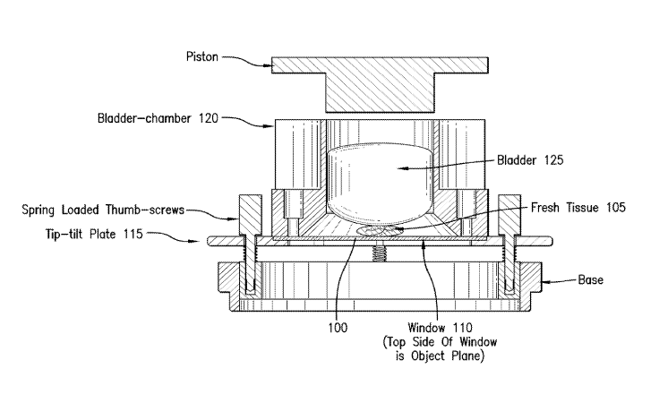
[00381 In particular, Figure 1 illustrates a side cross-sectional view of an
exemplary
embodiment of the tissue-mounting device 100, with no force applied to a
bladder 125, which
can perform an exemplary procedure shown in Figure 17. To flatten the desired
(e.g., lower)
surface of the tissue 105, a user can place the tissue 105 at the center of a
window 110 of
such exemplary tissue-mounting device 100 (e.g., procedure 1705 in Figure 17).
Then, the
- 8 -
CA 02881790 2015-02-11
WO 2014/028439
PCT/US2013/054653
user can apply a surgical lubricant on the top surface of the window 110
(e.g., the surface
where the tissue can be placed) around the sample, for example, approximately
5 mm outside
a border of the sample (e.g., procedure 1710 in Figure 17). Then, the window
110 can be
placed on a tip-tilt plate 115 (e.g., procedure 1715 in Figure 17) followed by
installation of a
polycarbonate bladder-chamber 120 on the tip-tilt plate 115 (e.g., procedure
1720 in Figure
17). The exemplary tissue-mounting device 100 for fresh tissue 105 shown in
Figure 1 can
have no force applied to the bladder 125. Under this nominal condition, the
tissue surface
(e.g., a lower surface of tissue 105), which can be imaged, may not be
flattened on to the
object plane.
100391 Figure 2 shows a side cross-sectional view of the exemplary tissue-
mounting device
100 of Figure 1 with an inserted piston 205, during operation thereof. In
particular, as shown
in Figure 4, which illustrates a perspective isometric (e.g., 3D) view of the
exemplary tissue-
mounting device 100 of Figure 1, with separate exemplary components
illustrated therein, a
polycarbonate piston 205 can be inserted into the bladder-chamber 120 of the
tissue-
mounting device 100 of Figure 1 (e.g., procedure 1725 in Figure 17), and
pressed down
gently to apply pressure on the bladder 125 (e.g., procedure 1730 in Figure
17). This
operation and ii-oce can flatten a lower surface of the tissue 105 against the
window 110, and
thus provide the tissue 105 into a desired 2D plane. The exemplary
system/apparatus, which
can. be used to facilitate such flattening of the tissue, is illustrated in
Figure 4, which can
facilitate the use of a microscope to analyze the flattened surface of the
tissue.
[0040] According to an exemplary embodiment of the present disclosure,
position and
orientation on a 2D plane in terms of tip and tilt, relative to the optical
axis of the
microscope, can be provided as shown in Figure 3, which illustrates a side
cross-sectional
view of the exemplary tissue-mounting device 100 of Figure 1 installed in a
microscope 300,
which can be adjusted with spring-loaded thumbscrews 405 shown in Figure 4.
This can
CA 02881790 2015-02-11
WO 2014/028439
PCT/US2013/054653
facilitate an exemplary adjustment of the window 110 so that it can be
parallel to the "object
plane" of the microscope. Such exemplary system and method, according to an
exemplary
embodiment of the present disclosure can facilitate a desired surface of the
tissue 105 to
conform to the object plane of the microscope 300, to facilitate accurate and
repeatable
imaging and m.osaicing over large areas. The exemplary embodiment and
implementation of
the mounting device can be robust to facilitate a repeatable operation during
extended periods
of time. Thus, the use of such fresh tissue mounting devices in confocal
mosaicing
microscopy, can enable rapid pathology at the bedside in diverse settings
(e.g., for detection
of residual cancer margins to guide surgery in surgical settings, and for
screening/diagnosis
of cancers to guide the examination of biopsies in clinical settings).
[0041] The exemplary flattening procedure illustrated in Figure 18 can also be
accomplished
with another mounting device according to a further exemplary embodiment of
the present
disclosure, as illustrated in Figures 5-9. Thus, for example, as an initial
step for the
exemplary procedure to flatten the desired (e.g., lower) surface of the tissue
505, the user can
place the tissue 505 at a center of the cassette 510 (e.g., procedure 1805 of
Figure 18),
followed by placing the bladder 515 on the sample (e.g., procedure 1810 of
Figure 18), which
is shown in Figure 5. Such placement can also be done automatically by an
automatic device,
such as, for example, a robotic device, etc. Then, the user and/or the
automatic device can
close the cassette lid 520 (e.g., procedure1815 of Figure 18). Such exemplary
closure of the
lid 520 can apply pressure on the bladder 515 which can flatten the lower
surface of the tissue
505 against the bottom surface of the cassette 510 into the desired 2D plane,
as shown in
Figure 6. Then, as also illustrated in Figure 6, the cassette 510 can be
placed on the tip-tilt
plate 525, and locked down with the holding clamps 605 (e.g., procedure 1020
of Figure 18).
10042] The 2D plane's position and orientation in terms of tip and tilt,
relative to the optical
axis of the microscope, can be adjusted with spring-loaded thumbscrews 530.
This can
- 10-
CA 02881790 2015-02-11
WO 2014/028439
PCT/US2013/054653
facilitate an adjustment of the window so that it can be parallel to the
object plane or the
image plane 705, or approximately perpendicular to the optical axis of the
microscope 710, as
shown in Figure 7.
[0043] Figure 8 is a perspective isometric (e.g., 3D) view of the exemplary
tissue-mounting
device of Figure 5, with separate exemplary components illustrated therein.
Figure 9
provides another perspective isometric (e.g., 3D) view of the exemplary tissue-
mounting
device of Figure 5, with such separate exemplary components illustrated
therein.
[0044] The exemplary flattening procedure illustrated in Figure 19 can also be
accomplished
with another mounting device according to a further exemplary embodiment of
the present
disclosure, as illustrated in Figure 10. To flatten the desired (e.g., lower)
surface, the user can
place the fresh tissue 1005 on the glass imaging window 1010 (e.g., procedure
1905 of Figure
19) and then placing the micro-pin array 1015 on the tissue 1005 (e.g.,
procedure1910 of
Figure 19). Then, the user can apply a force on the pin array 1015 to flatten
the lower surface
of the tissue 1005 against the top surface of the imaging window 1010 into the
desired 2D
plane (e.g., procedureI915 of Figure 19). An imaging device 1030, which can
include an
objective lens 1020 and a laser beam 1025, can be used to image to fresh
tissue 1005 (e.g.,
procedure 1920 of Figure 19).
[0045] The exemplary flattening procedure illustrated in Figure 20 can also be
accomplished
with another mounting device according to a further exemplary embodiment of
the present
disclosure, as illustrated in Figure 11. To flatten the desired (e.g., lower)
surface the user can
place the fresh tissue 1105 on the imaging window 1110 followed by placing the
tissue/glass
window in a bag (e.g., a thin silicon bag) 1115 (e.g., procedure 2005 of
Figure 20). Then, the
user can apply a vacuum 1120 to the silicon bag 1115 (e.g., procedure 2010 of
Figure 20).
This can apply atmospheric pressure, flattening the tissue 1105 against the
top surface of the
imaging window 110 into the desired 21) plane (e.g,, procedure 2015 of Figure
20).
-11-
CA 02881790 2015-02-11
WO 2014/028439
PCT/US2013/054653
10046] Figure 12A shows a side view of an exemplary illustration of a result
of the tissue that
may not be flattened, and thus, the object plane 1205 can likely not be
parallel to the image
plane 1210, and the optical axis may not be orthogonal to the image plane.
Figure 123
provides a side view of a possible result when the tissue can be flattened
using one or more
exemplary devices according to the present disclosure, thus making the object
plane parallel
to the image plane and the optical axis orthogonal to the image plane.
100471 Tissue fixturing can be utilized when acquiring large number of images
for mosaicing.
Indeed, the exemplary desired tissue surface (e.g., to be imaged) can
preferably be flattened,
and positioned and oriented so as to be held approximately parallel to the
microscope
objective lens' object (e.g., focal) plane. Thus, when the tissue can be
translated in, for
example, two dimensions, the surface can remain at least approximately in the
lens' focal
plane. If the tissue surface can be tilted, then the lens' focal plane (e.g.,
imaging) can either
"sink into" or "lift off' the tissue surface.
100481 Figures 13A-16 show various illustrations of exemplary embodiments of
the
exemplary tissue-mounting devices in various stages of an exemplary operation.
For
example, Figure 13A illustrates the exemplary tissue mounting device betbre an
exemplary
sample is placed thereon. Figure 133 illustrates the exemplary tissue mounting
device
having an exemplary slide/window 1305 placed thereon, Figure 13C illustrates
the
exemplary tissue mounting device having an exemplary plate 1310 placed on the
exemplary
slide/window 1305. Figure 13D has an exemplary bladder chamber 1315 placed on
the
exemplary plate 1310. Figure 13E illustrates the exemplary tissue mounting
device having an
exemplary piston holder 1320 placed on the exemplary bladder holder 1315.
Figures 13F and
14 illustrate the exemplary tissue mounting, device having an exemplary tissue
sample 1325
placed inside of the exemplary bladder chamber 1315. Figures 15A-15C
illustrate the
exemplary tissue mounting device having an exemplary bladder 1305 placed
inside of the
12
CA 02881790 2015-02-11
WO 2014/028439
PCT/US2013/054653
exemplary bladder chamber 1315. Figure 15D illustrates the exemplary tissue
mounting
device having a ball bearing ring 1510 placed inside of the bladder chamber
1315. Figure
15E illustrates the exemplary tissue mounting device having a cover 1515
placed thereon.
Figure 16 illustrates the exemplary tissue mounting device being used to image
an exemplary
tissue sample 1325.
[0049] The foregoing merely illustrates the principles of the disclosure.
Various
modifications and alterations to the described embodiments will be apparent to
those skilled
in the art in view of the teachings herein. It will thus be appreciated that
those skilled in the
art will be able to devise numerous systems, arrangements, and procedures
which, although
not explicitly shown or described herein, embody the principles of the
disclosure and can be
thus within the spirit and scope of the disclosure. In addition, all
publications and references
referred to above can be incorporated herein by reference in their entireties.
It should be
understood that the exemplary procedures described herein can be stored on any
computer
accessible medium, including a hard drive, RAM, ROM, removable disks, CD-ROM,
memory sticks, etc., and executed by a processing arrangement and/or computing
arrangement which can be and/or include a hardware processors, microprocessor,
mini,
macro, mainframe, etc., including a plurality and/or combination thereof. In
addition, certain
terms used in the present disclosure, including the specification, drawings
and claims thereof,
can be used synonymously in certain instances, including, but not limited to,
for example,
data and information. It should be understood that, while these words, and/or
other words
that can be synonymous to one another, can be used synonymously herein, that
there can be
instances when such words can be intended to not be used synonymously.
Further, to the
extent that the prior art knowledge has not been explicitly incorporated by
reference herein
above, it can be explicitly being incorporated herein in its entirety. All
publications
referenced can be incorporated herein by reference in their entireties.
- 13