Note: Descriptions are shown in the official language in which they were submitted.
CA 02881892 2015-02-11
= H8323311CA
SELF-PROPELLED AGRICULTURAL MACHINE WITH DUAL DRIVING MODES
CROSS REFERENCE TO RELATED APPLICATION
[0001] This application claims the benefit of U.S. Provisional
Application No.
61/938,257, filed February 11, 2014, which is hereby incorporated by reference
in its
entirety.
BACKGROUND OF THE INVENTION
Field of Invention
[0002] The present disclosure is generally related to
agricultural machines and,
more particularly, self-propelled windrowers.
Description of Related Art
[0003] Self-propelled windrowers utilize a dual-path steering
system to achieve
maximum maneuverability while cutting crops in the field. However, this
steering system
is not ideal for high speed transport due to the machine's inherent
instability. In
addition, the machine is not suited for pulling a towed implement, such as a
header with
a transport kit installed, due to a zero radius turning that the machine is
capable of via
the dual-path steering functionality. Such a maneuver, even if unintentional,
may result
in the windrower and towed implement becoming "jack-knifed."
OVERVIEW OF THE INVENTION
[0004] In one embodiment, the invention is directed a windrower
machine
operable in two steering modes selectable by an operator of the machine, the
dual
steering modes being a dual-path steering mode and a tailwheel steering mode,
the two
steering modes being mutually exclusive. The machine includes a chassis and an
engine mounted on the chassis. The machine also includes plural drive wheels
coupled
to the chassis and a ground drive system having plural wheel motors and plural
hydraulic wheel propel pumps coupled to a respective one of the plural drive
wheels, the
hydraulic wheel propel pumps being powered by the engine and each wheel motor
being
powered by its respective hydraulic wheel propel pump. The machine also has
plural
tailwheel caster assemblies coupled to opposing sides of the chassis, each
tailwheel
caster assembly having a tailwheel caster, a sensor, and a steering cylinder
configured
to operably control a steering position of the tailwheel caster when in the
tailwheel
1
CA 02881892 2015-02-11
H8323311CA
steering mode. The machine also has a user interface with a steering wheel and
a
forward-neutral-reverse (FNR) lever operable to control the ground drive
system, the
FNR lever having a forward position, a neutral position and a reverse
position. The
machine also has a controller configured to selectably operate the ground
drive system
in either the dual path steering mode or in the tailwheel steering mode. The
ground
drive system drives the plural drive wheels in either the same direction or in
the opposite
direction of rotation relative to each other depending on the position of the
steering
wheel and FNR lever and the position of tailwheel casters are not controlled
by the
steering cylinders but are permitted unconstrained rotation while in the dual-
path
steering mode. The ground drive system drives the plural drive wheels
concurrently
only in the same direction of rotation and being incapable of counter
rotation, and the
steering cylinder provides controlled and limited steer-rotation of the
tailwheel caster
based in part on tailwheel caster steer position information received from the
sensor in
the tailwheel steering mode.
[0005] In another embodiment, the invention is directed to a method
implemented in a machine including in a first steering mode, causing a left
drive wheel
and a right drive wheel to concurrently rotate, wherein the rotation of the
left drive wheel
is in a direction opposite that of the rotation of the right drive wheel; and
in a second
steering mode non-overlapping in operation with the first steering mode,
causing the left
drive wheel and the right drive wheel to rotate concurrently in only a same
direction.
[0006] These and other features and advantages of this invention are
described
in, or are apparent from, the following detailed description of various
exemplary
embodiments of the systems and methods according to this invention.
BRIEF DESCRIPTION OF THE DRAWINGS
[0007] Many aspects of the disclosure can be better understood with
reference
to the following drawings. The components in the drawings are not necessarily
to scale,
emphasis instead being placed upon clearly illustrating the principles of the
present
disclosure. Moreover, in the drawings, like reference numerals designate
corresponding
parts throughout the several views.
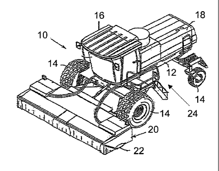
[0005] FIG. 1 is a schematic diagram that illustrates, in front
perspective view,
an example machine in which an embodiment of a dual mode steering system may
be
implemented.
2
CA 02881892 2015-02-11
H8323311CA
[0006] FIG. 2 is a schematic diagram that illustrates, in top fragmentary
plan
view, an embodiment of an example windrower equipped with an embodiment of an
example dual mode steering system.
[0007] FIG. 3 is a schematic diagram that illustrates, in top fragmentary
plan
view, an embodiment of an example windrower operating in a dual-path steering
mode.
[0008] FIG. 4 is a schematic diagram that illustrates, in top fragmentary
plan
view, an embodiment of an example windrower operating in a tailwheel steering
mode.
[0009] FIG. 5A is a flow diagram that illustrates an embodiment of an
example
dual-path steering mode method.
[0010] FIG. 5B is a flow diagram that illustrates an embodiment of an
example
tailwheel steering mode method.
[0011] FIG. 6A is a block diagram of an embodiment of an example dual
mode
steering system.
[0012] FIG. 6B is a block diagram of an embodiment of an example
controller
used in an embodiment of an example dual mode steering system.
[0013] FIG. 7 is a flow diagram that illustrates an embodiment of an
example
dual mode steering method.
DESCRIPTION OF EXAMPLE EMBODIMENTS
[0014] Certain embodiments of a dual mode steering system and method are
disclosed that enable a self-propelled machine, such as a self-propelled
windrower, to
operate in two distinct steering modes: a dual-path steering mode and a
tailwheel
steering mode. In the dual-path steering mode, the windrower drives and
operates like
a typical windrower in the sense that all steering is accomplished through
differential
wheel speeds and one or more tailwheel casters are free to rotate. In the
tailwheel
steering mode, the tailwheel casters are directly controlled by steering
cylinders through
a fixed angle of steer-rotation, and plural hydraulic wheel propel pumps are
reconfigured
by a controller to enable only forward and reverse machine travel. In effect,
the
tailwheel steering mode enables the windrower to steer similarly to a combine,
forage
harvester, or other rear wheel steered machines.
[0015] By contrast, in some conventional windrowers, the rear wheels are
controlled by the steering wheel, but not according to a directly sensed,
closed loop
feedback mechanism, and only beyond a certain speed. Some conventional
windrowers
3
CA 02881892 2015-02-11
H8323311CA
reverse the operator station and drive the machine with the caster wheels in
front,
enabling a towing capability yet not addressing, at least sufficiently, the
risk of jack-
knifing of the combined machines. In short, neither of these conventional
systems is
capable of a true rear steering mode, and both have shortcomings resulting
from
operations of the dual-path manner of operation. Certain embodiments of a dual
mode
steering system, through its closed loop feedback system in tailwheel steering
mode
and reconfiguration of the ground drive system, provides for stable operation
and
minimized risk of jack-knifing the windrower.
[0016] Having summarized certain features of a dual mode steering system
of
the present disclosure, reference will now be made in detail to the
description of the
disclosure as illustrated in the drawings. While the disclosure will be
described in
connection with these drawings, there is no intent to limit it to the
embodiment or
embodiments disclosed herein. For instance, though emphasis is placed on a
machine
in the agricultural industry, and in particular, a self-propelled windrower,
certain
embodiments of a dual mode steering system may be beneficially deployed in
other
machines (in the same or other industries) where stable operation in transport
operations is desired and/or where zero radius turn functionality is
implemented.
Further, although the description identifies or describes specifics of one or
more
embodiments, such specifics are not necessarily part of every embodiment, nor
are all
of any various stated advantages necessarily associated with a single
embodiment. On
the contrary, the intent is to cover all alternatives, modifications and
equivalents included
within the spirit and scope of the disclosure as defined by the appended
claims. Further,
it should be appreciated in the context of the present disclosure that the
claims are not
necessarily limited to the particular embodiments set out in the description.
[0017] Note that references hereinafter made to certain directions, such
as, for
example, "front", "rear", "left" and "right", are made as viewed from the rear
of the
windrower looking forwardly.
[0018] Reference is made to FIG. 1, which illustrates an example
agricultural
machine where an embodiment of a dual mode steering system may be implemented.
One having ordinary skill in the art should appreciate in the context of the
present
disclosure that the example agricultural machine, depicted in FIG. 1 as a self-
propelled
windrower 10, is merely illustrative, and that other machines and/or
components with
like functionality may deploy certain embodiments of a dual mode steering
system. The
self-propelled windrower 10 is operable to mow and collect standing crop in
the field,
4
CA 02881892 2015-02-11
=
H8323311CA
condition the cut material as it moves through the machine to improve its
drying
characteristics, and then return the conditioned material to the field in a
windrow or
swath. In some implementations, the windrower 10 may tow an implement (not
shown).
The windrower 10 may include a chassis or frame 12 supported by wheels 14
(although
tracks may be used in some embodiments, or other configurations in the number
and/or
arrangement of wheels may be used in some embodiments) for movement across a
field to be harvested. The chassis 12 carries a cab 16, within which an
operator may
control certain operations of the windrower 10, and a rearwardly spaced
compartment
18 housing a power source (not shown) such as an internal combustion engine.
The
chassis 12 also supports a ground drive system that, in one embodiment, when
powered
by the engine, causes differential rotation of the wheels according to a dual
path
steering mechanism as is known in the art.
[0019] A coupled working implement, depicted in FIG. 1 as a
harvesting header
20, is supported on the front of the chassis 12 in a manner understood by
those skilled
in the art. The header 20 may be configured as a modular unit and consequently
may
be disconnected for removal from the chassis 12. As is also known in the art,
the
header 20 has a laterally extending crop cutting assembly 22 in the form of a
low profile,
rotary style cutter bed located adjacent the front of the header 20 for
severing crop from
the ground as the windrower 10 moves across a field. However, one skilled in
the art will
understand that other types of crop cutting assemblies 22, such as sickle
style cutter
beds, may also be used in some embodiments.
[0020] The windrower 10 also includes a dual mode steering system 24,
which
may in one embodiment include one or more controllers, a ground drive system,
a
tailwheel caster system, and a plurality of sensors that monitor, in real
time, positions of
one or more machine navigation controls and a respective steering position of
each
tailwheel caster, as further described below. The dual mode steering system 24
enables
switching between, and mutually exclusive operation of, dual-path steering and
tailwheel
steering modes.
[0021] During a harvesting operation, the windrower 10 (with or
without a towed
implement) moves forward through the field with the header 20 lowered to a
working
height. The steering modes may be selected by an operator (e.g., residing in
the cab 16
or located remotely in some embodiments), or the dual mode steering system 24
may
transition the windrower 10 between modes automatically (e.g., at a defined
ground
speed and/or based on other parameters or conditions).
CA 02881892 2015-02-11
H8323311CA
[0022]
Referring now to FIG. 2, shown in fragmentary, overhead plan view is the
example windrower 10 of FIG. 1. It should be appreciated, within the context
of the
present disclosure, that the example construction of the windrower 10 depicted
in FIG. 2
is merely illustrative of a type of environment in which an embodiment of a
dual mode
steering system 24 may be implemented, and that other designs or machines may
likewise provide a suitable environment with beneficial effect. As shown (with
certain
well-known features omitted for brevity and clarity), the windrower 10 is
depicted with
the header 20 and the chassis 12, which is coupled to the header 20 and to the
wheels
14 (including rear tailwheel casters 14A, where "A" signifies a rear tailwheel
or caster as
opposed to a front drive wheel). While the tailwheel casters 14A are described
as being
in the rear of the windrower 10 as directed to the Figures, one skilled in the
art will
understand that the windrower 10 may be operated in both directions such that
the
tailwheel casters 14A may lead the drive wheels 14 in certain driving
conditions such as
high-speed, on-road operations. In one embodiment, the dual mode steering
system 24
comprises a tailwheel caster system 26, a ground drive system 28, and one or
more
controllers, such as controllers 30A and 30B (as described further below).
[0023] In one embodiment, the tailwheel caster system 26 comprises a manifold
32 and
two(2) tailwheel caster assemblies 34 (left rear) and 36 (right rear). In
some
embodiments, a different quantity of tailwheel caster assemblies 34, 36 and/or
manifolds
32 may be used, and in some embodiments, the tailwheel caster assemblies 34
and 36
integrate functionality of the manifold 32. The manifold 32 comprises one or
more
control valves proportional valves and/or pilot valves that control the flow
of hydraulic
fluid into and out of the tailwheel caster assemblies 34 and 36. The manifold
32 is
operably coupled to the controller 30B, the latter providing commands to the
manifold 32
based on input from one or more machine navigation controls, as described
further
below. In some embodiments, functionality of the controller 30B may be
integrated with
the controller 30A, such that commands are provided to the manifold 32 via the
controller 30A. In some embodiments, the controller 30B may provide commands
to
steering cylinders that integrate functionality of the manifold 32. Focusing
on the
tailwheel caster assembly 34 (with the same or similar applicability to the
tailwheel
caster assembly 36, the description of the same omitted here for brevity), in
one
embodiment, the tailwheel caster assembly 34 comprises a steering cylinder 38,
a rod
40, a pivot arm 42, hydraulic fluid lines 44, a sensor 46 (represented
schematically by a
triangle in FIG. 2), and the rear or tailwheel caster 14A. Note that some
embodiments of
6
CA 02881892 2015-02-11
H8323311CA
the tailwheel caster assembly 34 may include additional, fewer, and/or
different
components, in the same or different arrangement. Certain portions of, or
associated
with, the tailwheel caster assemblies 34 and 36 and/or the chassis 12 are
shown in
fragmentary view to avoid obfuscating operations with known structures. The
steering
cylinder 38 houses a piston (or plural pistons in some embodiments) that
slides back
and forth within the interior of the steering cylinder 38 based on hydraulic
fluid
displacement, as triggered and controlled by the control valves of the
manifold 32 and
conveyed over the fluid lines 44 as would be understood by one skilled in the
art. In one
embodiment, the control valves enable hydraulic fluid on both sides of the
piston to be at
the same pressure when in the dual-path steering mode such that the steering
cylinder
38 freely moves as dictated by rotation of the tailwheel caster 14A. The
steering
cylinder 38 is coupled to the rod 40 that is coupled to, and moves
synchronously with,
the internal piston, which directly causes the pivot arm 42 to pivot or rotate
(e.g.,
pivoting along a vertical or near vertical axis, enabling rotation to the left
and right) the
tailwheel caster 14A in the tailwheel steering mode. In the tailwheel steering
mode, the
sensor 46 senses the position of the left tailwheel caster 14A (e.g., the
steer-position),
providing feedback to the controller 30B. The
controller 30B, in turn, provides
commands to the control valve(s) of the manifold 32 based on the feedback,
enabling
precise adjustment of the fluid displacement over the hydraulic fluid lines 44
into and out
of the steering cylinder 38 to enable a controlled (e.g., constrained to less
than 360
degrees of steer rotation) adjustment of the steering position of the left
tailwheel caster
14A.
[0024]
Continuing, the windrower 10 comprises an engine 48, the ground drive
system 28, and a header drive system that comprises a header drive pump 50
that is
fluidly coupled to header drive motors 52 and 54 via hydraulic fluid lines,
such as
hydraulic fluid line 56, as is known. The ground drive system 28 is powered by
the
engine 48, which is mounted to the chassis 12. The ground drive system 28
comprises
a pump drive gearbox 58 that is coupled to the engine 48. The ground drive
system 28
further comprises a left wheel propel pump 60 coupled to the pump drive
gearbox 58,
and further coupled to a left wheel drive motor 62 via hydraulic fluid lines,
such as
hydraulic fluid line 64. The ground drive system 28 also comprises a right
wheel propel
pump 66 coupled to the pump drive gearbox 58, and further coupled to a right
wheel
drive motor 68 via hydraulic fluid lines, such as hydraulic fluid line 70.
Although depicted
as comprising a by-wire system, other hydraulic mechanisms may be used to
facilitate
7
CA 02881892 2015-02-11
H8323311CA
ground transportation in some embodiments, and hence are contemplated to be
within
the scope of the disclosure.
[0025] In
dual-path steering mode operation, in one embodiment, software in the
controller 30A provides for control of the ground drive system 28. Sensors are
located
on or proximal to the machine navigation controls, or generally, a user
interface 72 (e.g.,
which includes a steering wheel and a forward-neutral-reverse (FNR) lever) in
the cab
16 (FIG. 1), where operator manipulation of the steering wheel and/or FNR
lever causes
movement of the same that is sensed by the sensors. These sensors feed signals
to
the controller 30A, which in turn provide control signals to the propel pumps
60 and 66
to achieve the requested speed and travel direction. The signaling from the
controller
30A causes a change in fluid displacement in the respective propel pumps 60
and 66,
each displacement in turn driving the respective wheel drive motors 62 and 68
via
hydraulic fluid lines 64 and 70. With continued reference to FIG. 2, attention
is directed
to FIG. 3, which illustrates the dual-path steering mode using select
components of the
windrower 10 depicted in FIG. 2 for illustration. The dual-path steering mode
generally
comprises the traditional dual-path steering that most self-propelled
windrowers operate
under, where all steering for the windrower is accomplished through
differential speeds
of the two drive wheels. In this mode, the tailwheel casters 14A are free to
rotate, as
required by the movement of the windrower 10. As to the drive wheels 14,
rotating the
steering wheel may increase the speed of one drive wheel 14 (e.g., left) while
slowing
the speed of the other drive wheel 14 (e.g., right) by the same amount. In
other words,
steering for the windrower 10 may be achieved by increasing the speed of one
drive
wheel 14 while decreasing the speed of the opposite drive wheel 14 by the same
amount (yet, when both drive wheels 14 are rotating, they rotate in the same
direction).
Using some example values for illustration, if the windrower 10 is traveling
at 5 miles per
hour (MPH) forward, a steering command may result in the left drive wheel 14
driven at
a speed of 6 MPH and the opposing right drive wheel 14 driven at a speed of 4
MPH,
resulting in a right hand turn. As another example, if the windrower 10 is
traveling
forward at 1 MPH, the same steering command may result in the left drive wheel
14
being driven at 2 MPH forward and the opposing right drive wheel 14 driven to
a
complete stop (or equivalently, permitted to stop), with the magnitude of the
difference
in each case (e.g., 2 MPH) between the two drive wheels 14 being the same. At
slower
ground speeds in the dual-path steering mode, the drive wheels 14 may counter-
rotate
(as depicted by the dual-headed arrows adjacent each drive wheel 14, where one
drive
8
CA 02881892 2015-02-11
H8323311CA
wheel 14 is driven in the forward direction and the opposing drive wheel 14 is
driven in
reverse), causing the windrower 10 to spin in a zero radius turn. The zero
radius turn is
enabled during the neutral position of the FNR lever, and as described above,
involves
the drive wheels 14 rotating in opposite directions (e.g., while the left
front drive wheel
14 is rotating in a clockwise direction, for instance, the right front drive
wheel 14 is
rotating in a counter-clockwise direction). Stated otherwise, for the zero
radius turn
function, the front drive wheels are driven (e.g., via the propel pumps 60 and
66 and
wheel drive motors 62 and 68, as commanded or signaled by the controller 30A)
in
opposite directions (respectively forward and reverse).
Continuing the illustrative
examples described above, for a similar steering command and operation in
neutral, the
command results in the left drive wheel 14 driven at a speed of 1 MPH forward
and the
right drive wheel 14 driven 1 MPH in reverse (causing the windrower 10 to
counter
rotate to the right). The zero radius turn is a typical field operation used
to achieve
maximum maneuverability. Because of the manner of operation in the dual-path
steering mode, it is noted that the windrower 10 steers backwards when
traveling in
reverse (e.g., rotating the steering wheel to the left while backing up causes
the
windrower 10 to turn to the right, referred to as "S-steering."). At the same
time, as
noted above, the tailwheel casters 14A, which are un-driven, are free to
rotate (e.g.,
without constraint or limitation) in known manner in the dual-path steering
mode, as
depicted by the 360 degree arrowed circles representing the steer-rotation of
the
tailwheel caster 14A.
[0026] In
tailwheel steering mode operation, in one embodiment, software in the
controller 30A provides for control of the ground drive system 28, and
software in the
controller 30B provides control for the tailwheel caster system 26. In
general, the
tailwheel casters 14A operate according to a steer-rotation that is positively
controlled,
and the propel system of the ground drive system 28 is reconfigured to be
incapable of
counter rotation (e.g., the zero radius turn). Referring to FIGS. 2 and 4, the
controller
30A drives the ground drive system 28 in similar manner to that of the dual-
path steering
mode, except the controller 30A prevents counter-rotation of the front drive
wheels 14,
as depicted by the "X" through the dual-arrows located adjacent the wheels 14
in FIG. 4.
It is noted that for a by-wire system as depicted in FIG. 4, this
reconfiguration of the
hydrostatic propel system may be achieved in part or entirely within software,
though in
some embodiments, such as operating under a mechanically controlled drive
system,
the reconfiguration may involve physical and/or hydraulic changes as should be
9
CA 02881892 2015-02-11
H8323311CA
appreciated by one having ordinary skill in the art. In the tailwheel steering
mode, when
the machine is in neutral (e.g., the position of the FNR lever), rotation of
the steering
wheel only affects the angle of the tailwheel casters 14A and does not result
in the
machine operating according to a zero radius turn as it does in the dual-path
steering
mode. The ground drive system 28 enables drive wheel speeds to differ only
enough to
provide a differential effect, which results in the front drive wheel
rotation, when
concurrently driven, only in the same direction (e.g., either both rotating
forward or both
rotating in reverse). In reverse, the steering effect is the same or similar
to that
achieved for any wheel steered machine. For the tailwheel caster system 26,
the
controller 30B and each tailwheel caster assembly 34 and 36, respectively,
cooperate as
a closed loop feedback control system, wherein the steer-rotation of each
tailwheel
caster 14A is based on sensor input (e.g., from sensor 46 for the left
tailwheel caster
14A, and in one embodiment, using a sensor similarly configured for the right
tailwheel
caster wheel) and user interface input (e.g., from user interface 72), causing
the
steering cylinders (e.g., steering cylinder 38) to control the steer-rotation
of the tailwheel
casters 14A to limit the steer-rotation to a defined arc, as depicted in FIG.
4 by the dual-
arrows for each tailwheel caster 14A in less than the 360 degree arc that is
enabled
during the dual-path mode.
[0027]
Attention is now directed to FIGS. 5A and 5B (with continued reference to
FIG. 2), which are flow diagrams that illustrate methods 74 and 76 for the
dual-path
steering mode (FIG. 5A) and the tailwheel steering mode (FIG. 5B),
respectively. It
should be appreciated that the methods 74 and 76 illustrated in FIGS. 5A and
5B are
merely illustrative, and that in some embodiments, other and/or a different
quantity of
steps of the associated algorithm may be implemented. Referring to FIG. 5A,
user
interface inputs comprising steering wheel position 78 and FNR lever position
80 are
received by a dual mode steering module 82A. The dual mode steering module 82A
may be hardware, and/or software (e.g., including firmware in some
embodiments)
executed by one or more processors, such as embodied in the controller 30A.
The dual
mode steering module 82A determines a left (L) propel command (e.g., for the
left wheel
propel pump 60, FIG. 2) and a right (R) propel command (e.g., for the right
wheel propel
pump 66, FIG. 2). For instance, the left propel command equals the received
FNR lever
position 80 plus the steering wheel position 78, and the right propel command
equals
the received FNR lever position 80 minus the steering wheel position 78. The
dual
mode steering module 82A then outputs the left propel command 84 and the right
propel
CA 02881892 2015-02-11
H8323311CA
command 86 to enable differential wheel speeds (including zero radius turns
that involve
one of the drive wheels 14 rotating in a direction opposite to that of the
other drive wheel
14).
[0028]
Referring to FIG. 5B, the method 76 for the tailwheel steering mode
similarly comprises receiving an FNR lever position 80 and a steering wheel
position 78.
A dual mode steering module 82B receives the FNR lever position 80 and
determines
whether the FNR lever is positioned in the neutral (N) position. If so
("Yes"), the dual
mode steering module 82B outputs a zero (0) value for the left and right
propel
commands 83. In other words, the dual mode steering module 82B prevents
opposing
direction drive wheels in the tailwheel steering mode (but steering based on
the steering
wheel movement is still enabled, as described below). If the detected position
of the
FNR lever is not neutral ("No" to 82B), then calculation of the propel
commands may be
performed based on additional data as described in the following. A dual mode
steering
module 82C receives the steering wheel position 78 and calculates a turning
radius
(herein also referred to as a requested or target or targeted turning radius)
based on the
steering wheel position 78. A dual mode steering module 82D receives the
calculated
turning radius and the FNR lever position 80, and determines the left and
right propel
commands. In other words, the dual mode steering module 82D calculates the
left and
right propel commands based on the FRN lever position 80 and the requested
turning
radius, and outputs a left propel command 88 and a right propel command 90 to
cause
differential drive wheel rotation. A dual mode steering module 82E (e.g., as
implemented
in the controller 30B, though in some embodiments, the module 82E may be
implemented in the controller 30A) calculates left and right rear wheel
steering angles
required to achieve the requested turning radius. Also, the dual mode steering
module
82E receives left and right wheel (caster 14A) angle positions 92 and 94,
respectively,
which enables the dual mode steering module 82E to provide for precise control
of the
steering angles (e.g., the steer-rotation) based on input from the sensors 46
(e.g.,
position sensors) to output commands to the control valves of the manifold 32
(FIG. 1).
For instance, the dual mode steering module 82E outputs a signal to a left
rear wheel
(caster) steering valve 96 to cause (via fluid displacement) the steering
cylinder 38 to
steer-rotate the left tailwheel caster 14A, and outputs a signal to a right
rear wheel
(caster) steering valve 98 to achieve a similar affect on the right tailwheel
caster 14A
(FIG. 4). As noted above, the dual mode steering modules 82A-82E may be
implemented in a single controller (e.g., 30A or 30B), or divided among plural
controllers
11
CA 02881892 2015-02-11
H8323311CA
(e.g., modules 82A-82D in controller 30A and module 82E in controller 30B,
where the
controllers 30A and 30B are in wireless or wired communication with each
other).
[0029] Having
described some example operations of a dual mode steering
system 24, attention is directed to FIG. 6A, which illustrates an embodiment
of a dual
mode steering system 24. It should be appreciated within the context of the
present
disclosure that some embodiments may include additional components or fewer or
different components, and that the example depicted in FIG. 6A is merely
illustrative of
one embodiment among others. Further, in some embodiments, the dual mode
steering
system 24 may be distributed among plural machines. For
instance, sensing
functionality may reside locally with the windrower 10 (FIG. 1) whereas the
control of
machine steering and/or selection of modes may be administered remotely (e.g.,
via a
remote control server). The dual mode steering system 24 comprises one or more
controllers, such as the controllers 30A and 30B. The controllers 30A and 30B
are
coupled via one or more networks, such as network 100 (e.g., a CAN network or
other
network, such as a network in conformance to the ISO 11783 standard, also
referred to
as "Isobus"), to the ground drive system 28, the tailwheel caster system 26,
plural
sensors 102 (which may include sensor 46 of the tailwheel caster system 26, as
well as
other sensors of the windrower 10), the user interface 72, and a network
interface 104.
Note that dual mode steering system architecture depicted in FIG. 6A involves
the
sharing by the controllers 30A and 30B of the same bus(es), though in some
embodiments, other architectures may be used, such as the controllers 30A and
30B
daisy-chained such that all information (e.g., sensor input, etc.) is relayed
to the
controller 30B serving in a slave function via the controller 30A serving in a
master
function (or vice versa), or in some embodiments, the controllers 30A and 30B
may
function in a peer-to-peer relationship, where input from the tailwheel caster
system 26
and the associated sensors (e.g., 46) communicate solely with the controller
30B,
whereas the ground drive system 28 communicates only with the controller 30A.
These
and/or other variations in the architecture may be implemented, and hence are
contemplated to be within the scope of the disclosure.
[0030] With
continued reference to FIG. 2, the ground drive system 28 includes
the various components to enable the windrower 10 to traverse a field, such as
the
propel pumps 60 and 66, the wheel drive motors 62 and 68, and the hydraulic
fluid lines
64 and 70. The tailwheel caster system 26 comprises the various components
that
12
CA 02881892 2015-02-11
H8323311CA
enable controlled steering in the tailwheel steering mode, and includes the
tailwheel
caster assemblies 34 and 36. The sensors 102 include the position sensors of
the user
interface 72 (e.g., FNR lever and steering wheel), as well as the sensor 46 of
each of
the tailwheel caster assemblies 34 and 36 that monitor the left and right
tailwheel caster
angle positions (among other sensors, such as those used to monitor speed of
travel,
engine load, etc.). The sensors 102 may be embodied as non-contact (e.g.,
imaging,
Doppler, acoustic, terrestrial or satellite based, among other wavelengths,
inertial
sensors, etc.) and/or contact-type sensors (e.g., pressure transducers, speed
sensors,
Hall effect, position sensors, strain gauge, etc.), all of which comprise
known
technology. The user interface 72 may include one or more of a keyboard,
mouse,
microphone, touch-type display device, joystick, steering wheel, FNR lever, or
other
devices (e.g., switches, innmersive head set, etc.) that enable input and/or
output by an
operator (e.g., to respond to indications presented on the screen or aurally
presented)
and/or enable monitoring of machine operations. The network interface 104
comprises
hardware and/or software that enable wireless connection to one or more
remotely
located computing devices over a network (e.g., wireless or mixed wireless and
wired
networks). For instance, the network interface 104 may cooperate with browser
software or other software of the controllers 30A and/or 30B to communicate
with a
server device over cellular links, among other telephony communication
mechanisms
and radio frequency communications, enabling remote monitoring or control of
the
windrower 10 (FIG. 2). The network interface 104 may comprise MAC and PHY
components (e.g., radio circuitry, including transceivers, antennas, etc.), as
should be
appreciated by one having ordinary skill in the art.
[0031] In one
embodiment, the controllers 30A and/or 30B are configured to
receive and process information from the sensors 102, and communicate with the
ground drive system 28 and the tailwheel caster system 26 to cause desired
navigational movement of the windrower 10 (FIG. 1) based on the input of
information
from the sensors 102 (e.g., as prompted by sensed movement of components of
the
user interface 72, which may be prompted by an operator or occur
automatically). In
some embodiments, the controllers 30A and/or 30B may provide feedback of any
automatic or operator-invoked switch between dual-path mode and tailwheel
steering
mode via a display and/or aurally.
13
CA 02881892 2015-02-11
H8323311CA
[0032] FIG. 6B further illustrates an example embodiment of the
controller 30A.
The description associated with FIG. 6A for the controller 30A may similarly
apply to the
controller 30B. For instance, as set forth above, functionality of the dual
mode steering
modules 82A-82E (e.g., executable code) may reside within a single controller
(e.g.,
controller 30A or 30B), or be distributed among separate controllers 30A and
30B that
are in communication with each other. One having ordinary skill in the art
should
appreciate in the context of the present disclosure that the example
controller 30A is
merely illustrative, and that some embodiments of controllers may comprise
fewer or
additional components, and/or some of the functionality associated with the
various
components depicted in FIG. 6B may be combined, or further distributed among
additional modules, in some embodiments. It should be appreciated that, though
described in the context of residing in the windrower 10 (FIG. 1), in some
embodiments,
the controller 30A, or all or a portion of its corresponding functionality,
may be
implemented in a computing device or system located external to the windrower
10.
Referring to FIG. 6B, with continued reference to FIG. 6A, the controller 30A
is depicted
in this example as a computer system, but may be embodied as a programmable
logic
controller (PLC), field programmable gate array (FPGA), application specific
integrated
circuit (ASIC), among other devices. It should be appreciated that certain
well-known
components of computer systems are omitted here to avoid obfuscating relevant
features of the controller 30A. In one embodiment, the controller 30A
comprises one or
more processors (also referred to herein as processor units or processing
units), such
as processor 106, input/output (I/O) interface(s) 108, and memory 110, all
coupled to
one or more data busses, such as data bus 112. The memory 110 may include any
one
or a combination of volatile memory elements (e.g., random-access memory RAM,
such
as DRAM, and SRAM, etc.) and nonvolatile memory elements (e.g., ROM, hard
drive,
tape, CDROM, etc.). The memory 110 may store a native operating system, one or
more native applications, emulation systems, or emulated applications for any
of a
variety of operating systems and/or emulated hardware platforms, emulated
operating
systems, etc.
[0033] In the embodiment depicted in FIG. 6B, the memory 110 comprises an
operating system 114 and dual mode steering software 82. In one embodiment,
the dual
mode steering software 82 comprises one or more of the modules 82A-82E (FIGS.
3A-
3B). For the controller 30B (FIG. 2), the dual mode steering software 82 may
only
14
= CA 02881892 2015-02-11
H8323311CA
include module 82E, or in some embodiments, one or more of modules 82A-82D in
addition to module 82E. It should be appreciated that in some embodiments,
additional
or fewer software modules (e.g., combined functionality) may be deployed in
the
memory 110 or additional memory. In some embodiments, a separate storage
device
may be coupled to the data bus 112, such as a persistent memory (e.g.,
optical,
magnetic, and/or semiconductor memory and associated drives).
[0034] The dual mode steering software 82 receives input
corresponding the
steering wheel position 78, the FNR lever position 80, and in some embodiments
(e.g.,
when implementing functionality associated with software module 82E), the left
and right
wheel (caster) angle positions 92 and 94, respectively (see, e.g., FIGS. 3A-
3B). The
dual mode steering software 82 uses at least some of the information to
control
operation of the drive wheels 14. The dual mode steering software 82 further
determines
whether the neutral position is selected by the operator (e.g., corresponding
to the FNR
lever) to determine whether to enable zero radius functionality (in dual-path
steering
mode) or not (in tailwheel steering mode). The dual mode steering software 82
also
determines a turning radius based on the steering wheel position 78 according
to
mechanisms well-known in the art. In embodiments where the dual mode steering
software 82 includes module 82E, the dual mode steering software 82 calculates
left
and rear wheel (caster) steering angles needed to achieve the requested
turning radius,
based on feedback from the left and right wheel (caster) angle positions 92
and 94.
[0035] Execution of the dual mode steering software 82 may be
implemented by
the processor 106 under the management and/or control of the operating system
114.
In some embodiments, the operating system 114 may be omitted and a more
rudimentary manner of control implemented. The processor 106 may be embodied
as a
custom-made or commercially available processor, a central processing unit
(CPU) or
an auxiliary processor among several processors, a semiconductor based
microprocessor (in the form of a microchip), a macroprocessor, one or more
application
specific integrated circuits (ASICs), a plurality of suitably configured
digital logic gates,
and/or other well-known electrical configurations comprising discrete elements
both
individually and in various combinations to coordinate the overall operation
of the
controller 30A.
[0036] The I/O interfaces 108 provide one or more interfaces to the
network 100
and other networks. In other words, the I/O interfaces 108 may comprise any
number of
CA 02881892 2015-02-11
H8323311CA
interfaces for the input and output of signals (e.g., analog or digital data)
for conveyance
of information (e.g., data) over the network 100. The input may comprise input
by an
operator (local or remote) through the user interface 72 and input from
signals carrying
information from one or more of the components of the dual mode steering
system 24,
such as the sensors 102 and/or the network interface 104, among other devices.
[0037] When certain embodiments of the controller 30A (and controller
30B) are
implemented at least in part with software (including firmware), as depicted
in FIG. 6B, it
should be noted that the software (e.g., such as the modules 82) can be stored
on a
variety of non-transitory computer-readable medium for use by, or in
connection with, a
variety of computer-related systems or methods. In the context of this
document, a
computer-readable medium may comprise an electronic, magnetic, optical, or
other
physical device or apparatus that may contain or store a computer program
(e.g.,
executable code or instructions) for use by or in connection with a computer-
related
system or method. The software may be embedded in a variety of computer-
readable
mediums for use by, or in connection with, an instruction execution system,
apparatus,
or device, such as a computer-based system, processor-containing system, or
other
system that can fetch the instructions from the instruction execution system,
apparatus,
or device and execute the instructions.
[0038] When certain embodiment of the controller 30A (and controller 30B)
are
implemented at least in part with hardware, such functionality may be
implemented with
any or a combination of the following technologies, which are all well-known
in the art: a
discrete logic circuit(s) having logic gates for implementing logic functions
upon data
signals, an application specific integrated circuit (ASIC) having appropriate
combinational logic gates, a programmable gate array(s) (PGA), a field
programmable
gate array (FPGA), etc.
[0039] In view of the above description, it should be appreciated that
one
embodiment of a dual mode steering method 116, depicted in FIG. 7, comprises:
in a
first steering mode, causing a left drive wheel and a right drive wheel to
concurrently
rotate, wherein the rotation of the left drive wheel is in a direction
opposite that of the
rotation of the right drive wheel (118); and in a second steering mode non-
overlapping in
operation with the first steering mode, causing the left drive wheel and the
right drive
wheel to rotate concurrently in only a same direction. In other words, when
the left and
16
CA 02881892 2015-02-11
H8323311CA
right drive wheels do rotate concurrently, the rotation is only in the same
direction (and
not permitted in the reverse direction).
[0040] Any process descriptions or blocks in flow diagrams should be
understood as representing modules, segments, or portions of code which
include one
or more executable instructions for implementing specific logical functions or
steps in
the process, and alternate implementations are included within the scope of
the
embodiments in which functions may be executed out of order from that shown or
discussed, including substantially concurrently or in reverse order, depending
on the
functionality involved, as would be understood by those reasonably skilled in
the art of
the present disclosure.
[0041] In this description, references to "one embodiment", "an
embodiment", or
"embodiments" mean that the feature or features being referred to are included
in at
least one embodiment of the technology. Separate references to "one
embodiment", "an
embodiment", or "embodiments" in this description do not necessarily refer to
the same
embodiment and are also not mutually exclusive unless so stated and/or except
as will
be readily apparent to those skilled in the art from the description. For
example, a
feature, structure, act, etc. described in one embodiment may also be included
in other
embodiments, but is not necessarily included. Thus, the present technology can
include
a variety of combinations and/or integrations of the embodiments described
herein.
Although the control systems and methods have been described with reference to
the
example embodiments illustrated in the attached drawing figures, it is noted
that
equivalents may be employed and substitutions made herein without departing
from the
scope of the disclosure as protected by the following claims.
17