Note: Descriptions are shown in the official language in which they were submitted.
= CA 02881994 2015-02-13
WO 2014/046720
PCT/US2013/027909
SYSTEM AND METHOD FOR ADDRESSING A PNEUMATIC
EMERGENCY IN A HELPER LOCOMOTIVE
BACKGROUND OF THE INVENTION
Field of the Invention
[0001] The present invention relates to a system and method for addressing a
pneumatic
emergency initiated in a helper locomotive and, more particularly, to a system
and method of
improving braking safety and reducing brake system recovery time in an
electronically
controlled pneumatic (ECP)-equipped train after transmission of a brake pipe
emergency
dump command message by the helper locomotive associated with the train,
Description of Related Art
[0002] The air brake system on a train includes a brake pipe which extends the
length of
the train. The pressure is maintained in the brake pipe by the lead locomotive
except when
the engineer in the lead locomotive applies the brakes by releasing air
pressure. The drop in
air pressure propagates down the brake pipe causing brakes to be applied by
the locomotives
and all the cars in the train. With the advent of two-way end-of-train (EOT)
units, an
emergency braking event can be initiated by the engineer by causing air
pressure to be vented
simultaneously at the front and back of the train. The EOT unit is mounted on
a coupler of
the last car of the train, and specific coupler mounts have been designed to
allow a helper
locomotive to couple to the last train without damaging the EOT unit.
[0003] A helper locomotive may provide additional braking or motive power to
the train.
For example, in a train a mile long, a consist having three locomotives may
provide sufficient
power for a run along average grade terrain. However, a run over an above-
average grade
may require additional power in the fonn of a helper locomotive being attached
to the end of
the train just before traversing the increased grade. Once the train has
cleared the increased
grade, the helper locomotive is disconnected and may return to its point of
origin. Current
brake pipes of helper locomotives are connected to the train in one of two
manners: a direct
physical connection or a virtual connection. With a physical connection, the
brake pipe hose
of a helper locomotive has a connection to the train. This makes the brakes of
the helper
locomotive respond like any other car in the train, thus giving control of the
brakes to the
engineer in the lead locomotive. Coupling and uncoupling of the brake hose of
the helper
locomotive to the train is accomplished manually. Both operations expose
railroad personnel
to risk of serious injury. With a virtual connection, the brake pipe hose of
the helper
locomotive is connected 10 special radio-based helper equipment and the brake
pipe pressure
CA 02881994 2015-02-13
WO 2014/046720 PCT/US2013/027909
is con-ununicated between the train and the helper locomotive via the existing
radio system.
Therefore, a safer alternative in adding braking functionality to the helper
locomotive that
uses a virtual connection is found in electronically controlled pneumatic
(ECP) trains.
[0004] An ECP-equipped train relies on electronic signals, rather than changes
in brake
pipe air pressure, to activate brake valves on individual freight cars.
Because signal
propagation from the first to last car is instantaneous, the rate of brake
cylinder pressure
buildup can be increased. With conventional pneumatic brakes, brake cylinder
pressure
buildup time is carefully retarded to prevent the last cars in a train, where
the brakes have not
yet applied, from running into the first cars with fully developed brake
cylinder pressure.
With ECP, cylinder pressure buildup is about 6 to 7 psi/second for both
emergency and
service brake applications. The brakes can be applied, partially released, and
then reapplied
as often as necessary, within the 'ability of the locomotive compressors to
replenish reservoirs
on the cars of a long train.
[0005] In the context of a helper locomotive with a virtual brake pipe
connection, ECP-
equipped trains do not require that a physical brake pipe connection be made
between the
train and the helper locomotive. Specifically, a system is provided for
forming a virtual
brake pipe connection between the head-end-unit (HEU) of the helper locomotive
and the
HOT unit of the train. Thus, the EOT unit reads ECP braking commands from the
ECP
trainline and translates them into radio messages, which are sent to the
helper locomotive.
The system then sets the braking on the helper locomotive to match that of the
ECP braking
application on the train. A commercial system that implements the
aforementioned
functionality is known as HelperLinkrm by Wabtec Railway Electronics.
[0006] As is known in the art, the aforementioned system may also initiate
braking in the
context of issuing an emergency brake application to the associated train
based on a
pneumatic emergency experienced on the helper locomotive or if the engineer of
the helper
locomotive is aware of a situation affecting the train that would require an
emergency brake
application. In such an instance, thc emergency brake application involves the
transmission
of a brake pipe emergency dump cominand from the helper locomotive to the EOT
unit.
Upon receipt of the brake pipe emergency dump command, the EOT unit would open
the
brake pipe dump valve, which results in immediate discharge of the brake pipe
of the train,
and an immediate application of the brakes on all cars to an emergency level.
This sudden
and non-graduated removal of air from the brake pipe increases in-train forces
and results in
depletion of all air, which requires a lengthy recharging and testing of the
entire brake system
bethre the train may continue its travel.
2
= CA 02881994 2015-02-13
WO 2014/046720 PCTPUS2013/027909
[0007] Thus, there is a need for a system and method that overcomes or
addresses some or
all of the limitations of the existing ECP train systems and arrangements.
SUMMARY OF THE INVENTION
[0008] Generally, the present invention provides a system and method for
addressing a
pneumatic emergency in a helper train that address some or all of the
deficiencies and
drawbacks associated with existing electronically controlled pneumatic (ECP)-
equipped
trains and components.
[0009] Accordingly, in one preferred and non-limiting embodiment, provided is
a method
for improving braking safety and reducing brake system recovery time in an
electronically
controlled pneumatic (ECP)-equipped train after transmission of a brake pipe
emergency
dump command message by a helper locomotive associated with the train having
multiple
cars. This method includes: (a) receiving the brake pipe emergency dump
command message
at an end-of-train (EOT) unit associated with the train; (b) transmitting an
ECP emergency
brake request message from the EOT unit to at least one car in the train and a
head-end-unit
(HEU) of the train; (c) waiting a predetermined period of time after
transmitting the ECP
emergency brake request message, for receipt of an ECP head-of-train (HOT)
brake
command message transmitted by the HEU (e.g., indicating that the ECP
emergency brake
command has been received by the HEU); and (d) opening a brake pipe dump valve
if the
ECP HOT brake command message has not been issued to the at least one car in
the train
within the predetermined period of time. The ECP emergency brake request
message is a
message that requests that the train be stopped and/or a message that
identifies that the helper
locomotive has gone into a pneumatic emergency.
[0010] The brake pipe dump valve may be in fluid communication with a brake
pipe of the
train. The helper locomotive may be a pusher locomotive coupled to an end of
the train
without a physical connection to the brake pipe of the train. The
predetermined period of
time may be from about 1 to about 10 seconds, and preferably from about 3 to
about 5
seconds. The ECP HOT brake command message may be: an emergency train brake
command (TBC), or as is known in the art, a TBC=120% command; or some lesser
or
reduced brake command. Receipt of the brake pipe emergency dump command
message may
occur on an EOT radio network, and the EOT transmission of the ECP emergency
brake
request to the cars and to the ECP HEIJ, and receipt of the ECP HOT brake
command
message may occur on an ECP messaging network,
3
CA 02881994 2015-02-13
WO 2014/046720
PCT/US2013/027909
[0011] In a further preferred and non-limiting embodiment, provided is
directed to an EOT
unit for use in improving braking safety and reducing brake system recovery
time in an ECP-
equipped train after transmission of a brake pipe emergency dump command
message by a
helper locomotive associated with the train. This unit includes: a brake pipe
dump valve; an
EOT radio receiver for receiving the brake pipe emergency dump command
message; an ECP
transmitter for transmitting an ECP emergency brake request message; an ECP
trainline
receiver for receiving an ECP HOT brake command message; and a processor for
determining if the ECP HOT brake command message has been received within a
predetermined period of time after transmitting the ECP emergency brake
request message,
where, if a determination is made that the ECP HOT brake command message has
not been
received within the predetermined period of time, causing the brake pipe dump
valve to be
opened.
100121 In a further preferred and non-limiting embodiment, provided is a
system for
improving braking safety and reducing brake system recovery time in an ECP-
equipped train
after transmission of a brake pipe emergency dump command message by a helper
locomotive associated with the train. The system includes: an EOT radio
network; a helper
locomotive equipped with a virtual brake pipe connection, wherein the helper
locomotive is
configured to transmit the brake pipe emergency dump command message on the
EOT radio
network; an EOT unit situated on the train, wherein the EOT unit is configured
to receive the
brake pipe emergency dump corm-nand message from the EOT radio network, and in
response
thereto, transmit an ECP emergency braking request message on an ECP messaging
network,
wherein the EOT unit includes a brake pipe dump valve, and wherein at least
one car in the
train is configured to respond to an ECP emergency braking request message
from the ECP
messaging network from the EOT; and an HEU situated on the train, wherein the
HEU of the
train is configured to transmit an ECP HOT brake command message on the ECP
messaging
network, and wherein the EOT unit is further configured to open the brake pipe
dump valve if
the ECP HOT brake command message has not been received within a predetermined
period
of nine after transmitting the ECP emergency brake request message.
[0013] By utilizing an ECP EOT emergency brake command request to activate the
brakes
on the cars corresponding to an emergency braking command (e.g., TBC¨I 20%
command)
or corresponding to a lesser or reduced TBC brake command, as opposed to a
traditional EOT
brake pipe emergency dump command at the EOT unit, the benefits associated
with an ECP-
equipped train are realized. Specifically, the cars responding directly to the
ROT without
waiting for a command from the ECP HOT command yields a shorter stopping
distance; a
4
CA 02881994 2015-02-13
=
WO 2014/046720
PCT/US2013/027909
reduction of in-train forces; reduced wheel, brake shoe, and draft gear wear;
and a reduction
in the amount of brake system air utilized to recover from the brake
application, thereby
minimizing down-time.
[0014] With existing systems, a pneumatic emergency on the helper locomotive
would
result in the EOT activating its dump valve, and the brake pipe of the train
being exhausted.
All of the cars in the train would apply their brakes to an emergency level,
but not at the same
time. The cars nearest the EOT would apply their brakes the quickest.
Eventually a few cars
would broadcast that they were in a pneumatic emergency state, and the rest of
the cars
would apply their brakes to an emergency level, During the time when the brake
pipe was
exhausted, the reservoir levels on the car would remain constant at the
equalization level, and
would not rise. Any nominal pneumatic leaks on the cars, as is common to some
level, would
cause the reservoir levels to slowly drain down.
[00151 Recovery from the pneumatic emergency requires that the brake pipe be
fully
charged, and that all of the reservoirs on the cars be replenished. Depending
on the length of
the train, this recovery may take more than 1 5 minutes. By implementing the
system and
method of the present invention, the ECP EOT would hold-off activating the
dump valve in
lieu of transmitting an ECP EOT emergency brake request message over the ECP
network
that causes all of the cars to immediately activate their brakes. The
activation of the brakes
on the car will occur faster than with existing systems, resulting in a
shorter stopping
distance. Assuming the ECP HEU received the ECP EOT emergency brake request
message
and responded with an ECP EOT brake command message, the ECP EOT will refrain
from
activating the EOT dump valve and the brake pipe will remain charged. Since
the brake pipe
remains charged, all of the reservoirs on the cars in the train will pull air
from the brake pipe
and fully charge their reservoirs. Any nominal pneumatic leaks on the cars, as
is common to
some level, will be replenished with air from the brake pipe. Recovery from
the helper
emergency can occur as soon as the ECP logic allows it, without having to wait
for either the
brake pipe or the reservoirs on the ears in the train, to recharge.
Accordingly, the present
invention provides certain benefits and iinprovements for addressing pneumatic
emergencies
in helper locomotives.
[0016] These and other features and characteristics of the present invention,
as well as the
methods of operation and functions of the related elements of structures and
the combination
of parts and economies of manufacture, will become more apparent upon
consideration of the
following description and the appended claims with reference to the
accompanying drawings,
all of which form a part of this specification, wherein like reference
numerals designate
CA 02881994 2015-02-13
WO 2014/046720
PCT/US2613/027909
corresponding parts in the various figures. It is to be expressly understood,
however, that the
drawings are for the purpose of illustration and description only and are not
intended as a
definition of the limits of the invention. As used in the specification and
the claims, the
singular form of "a", "an", and "the" include plural referents unless the
context clearly
dictates otherwise.
BRIEF DESCRIPTION OF THE DRAWINGS
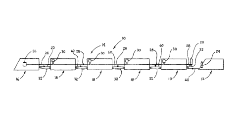
[0017] FIG. 1 is a schematic of one embodiment of a system for addressing a
pneumatic
emergency initiated by a helper locomotive associated with a train, in
accordance with the
principles of the present invention;
[0018] FIG. 2 is a schematic of one embodiment of an EOT unit, in accordance
with the
present invention; and
[0019] FIG. 3 is a flowchart outlining the one preferred operational sequence,
in
accordance with the principles of the present invention.
DETAILED DESCRIPTION OF THE INVENTION
[0020] For purposes of the description hereinafter, the terms "end", "upper",
"lower",
"right", "left", "vertical", "horizontal", "top", "bottom", "lateral",
"longitudinal" and
derivatives thereof shall relate to the invention as it is oriented in the
drawing figures.
However, it is to be understood that the invention may assume various
alternative variations
and step sequences, except where expressly specified to the contrary. It is
also to be
understood that the specific devices and processes illustrated in the attached
drawings, and
described in the following specification, are simply exemplary embodiments of
the invention.
Hence, specific dimensions and other physical characteristics related to the
embodiments
disclosed herein are not to be considered as limiting. Further any of the
steps, functions, or
determinations can be made by any suitable computing arrangement or processor,
whether a
standalone computer or a programming interface, module, software, firmware, or
other code
integrated with or implemented on an existing computing device or processor of
any of the
units discussed hereinafter.
[0021 I FIG. 1 depicts a schematic of one preferred and non-limiting
embodiment of a
system 10 for addressing a pneumatic emergency initiated by a helper
locomotive 12
associated with a train 14. The train 14 includes a locomotive 16 and one or
more cars 18
sequentially coupled thereto. The last car 18 includes an end-of-train (E0T)
unit 20 and the
locomotive 16 includes an electronically controlled pneumatic (ECP) head-end-
unit (HEU)
6
26, all communicatively connected via an electronically controlled pneumatic
(ECP)
messaging network (whether in hard-wired or wireless form). The HOT locomotive
16 is
mechanically coupled (via mechanical coupler 60) to the first car 18, adjacent
cars 18 are
mechanically coupled together, and the helper locomotive 12 is mechanically
coupled to the
last car 18 (and has a physical separation of the brake pipe). The helper
locomotive 12
preferably includes radio-based helper equipment 24 that communicates over an
EOT radio
network (preferably in wireless form) to the EOT unit 20 mounted on the last
car 18. It is to
be understood that functionality incorporated in the head-of-train HEU 26 may
be facilitating
or encompassed by respective separate components connected to and/or
configured to
interface with the HEU 26.
[0022] The train 14 includes an ECP trainline 28 communicatively connecting an
ECP
controller 30 of each car 18 to the ECP messaging network and, thereby, the
HEU controller
26. The train 14 also includes a brake pipe 32 running the length of the train
14, which
connects each car 18 with an adjacent car 18, and is terminated with the EOT
unit 20 at the
last car 18. The helper locomotive 12 may be a pusher locomotive coupled to an
end of the
train 14 without a physical connection to the brake pipe 32 of the train 14.
[0023] The radio-based helper equipment 24 of the helper locomotive 12 is
configured to
transmit a brake pipe emergency dump request message on the ECP messaging
network. It is
noted that ECP messages preferably occur only on the wired ECP network, while
messages
from the helper locomotive 12 occur over the radio-based EOT network. The HEU
26 of the
HOT locomotive 16 is configured to receive an ECP emergency brake request
message
(which is a message or includes content that requests that the train 14 be
stopped and/or that
identifies that the helper locomotive 12 has gone into a pneumatic emergency).
The HEU 26
of the HOT locomotive 16 is also configured to, in response to receipt of the
ECP emergency
brake request message, transmit an ECP HOT brake command message on the ECP
messaging network to at least one, and preferably, each ECP controller 30 and
the EOT unit
20. One example of an ECP HOT brake command message is a train brake command
of
120%, or a TBC=120% command. As is known in the art, a TBC= 120% command
corresponds to an ECP emergency brake application, as is discussed in
publication AAR
S4200: ECP (Cable-Based Brake System Performance Requirements), the contents
of which
may be referred to. However, it is to be understood that other suitable
degrees of braking
may be associated with the ECP HOT brake command message. It is further to be
understood that existing HEU 26 may be programmed to provide the
aforementioned
functionality.
7
CA 2881994 2018-02-01
100241 FIG. 2 is a schematic of one preferred and non-limiting embodiment of
the EOT
unit 20. According to this embodiment, the EOT unit 20 includes a housing 34
containing a
processor 36, a transmitter 37, and a receiver 38, all communicatively
connected to an
antenna 39. It is to be understood that the EOT unit 20 may include the
necessary
components (e.g., storage medium, circuitry, interface, software/firmware, and
the like) for
providing the fundamental functionality of any existing EOT unit. Existing EOT
units and
associated components are described in one or more of U.S. Patent Nos.:
4,487,060;
4,885,689; 5,016,840; 5,190,359; 5,235,849; 5,267,473; 5,383,717; and
5,873,638, all of
which may be referred to in their entirety. The EOT unit 20 also includes a
brake pipe dump
valve 40 in fluid communication with the brake pipe 32 of the train 14. The
EOT unit 20
may be connected to the ECP trainline 28, as shown in FIG. 1. As is known in
the art, receipt
of an appropriate signal at the EOT unit 20 results in appropriate mechanisms
opening the
brake pipe dump valve 40, resulting in release of the air along the entire
brake pipe 32 of the
train 14.
[0025] The receiver 38 and associated hardware are configured to receive a
brake pipe
emergency dump command message and to send the information to the processor
36. The
processor 36 and associated software are configured to send an ECP HOT brake
request
message over the ECP trainline 28 to the cars (e.g., the ECP controllers 30 of
each car) and to
the ECP HEU 26. Further, the processor 36 and associated software operating
thereon are
configured to determine if the ECP HOT brake request message has been received
within a
predetermined period of time after transmission of the ECP emergency brake
request
message.
[0026] In one preferred and non-limiting embodiment, the predetermined period
of time
may be in the range of about 1 second to about 10 seconds, and preferably in
the range of
about 3 seconds to about 5 seconds. However, it is to be understood that any
suitable time in
any suitable time measuring unit may be used in connection with the present
invention. It is
to be further understood that a suitable time would preferably be a time
period in which it is
likely or determined that an ECP HOT brake command message should have already
been
transmitted and been received. The predetermined period of time may be pre-
programmed in
the EOT unit or may be dynamically modified or programmed based on a per-
situation basis
before or during train operation, based on certain conditions, such as train
parameters,
operational conditions, environmental conditions, computer logic assessments,
etc. The
processor 36 and associated software are also configured to open the brake
pipe dump valve
8
CA 2881994 2018-02-01
CA 02881994 2015-02-13
WO 2014/046720 PCT/US2013/027909
40 if a deten-nination is made that the ECP HOT brake command message has not
been
received within the predetermined period of time.
[0027] A method for improving braking safety and reducing brake system
recovery time in
the ECP-equipped train 14 after transmission of a brake pipe emergency dump
command
message by the helper locomotive 12 associated with the train 14 will now be
discussed in
accorthuice with one preferred and non-limiting embodiment of the present
invention. With
continued reference to FIGS. 1 and 2, FIG. 3 depicts a flowchart for
illustrating the
operational steps in implementing one embodiment of the present invention, If
the engineer
on the helper locomotive 12 is aware of a situation affecting the train 14
that would require
an emergency brake application, the engineer initiates a brake pipe emergency
dump
command. Specifically, the radio-based helper equipment 24 of the helper
locomotive 12
transmits the brake pipe emergency dump command message to the EOT unit 20 of
the car 18
of the train 14, as shown in step 50. The EOT unit 20 receives the brake pipe
emergency
dump command message at step 51 and, in response thereto, transmits the ECP
emergency
brake request message to the HEU 26 of the locomotive 16 of the train 14, as
shown in step
52.
100281 Thereafter, as shown in step 53, the ROT unit 20 waits a predetermined
period of
time after transmitting the ECP emergency brake request message. Appropriate
logic in the
EOT unit 20, as provided for by the processor 36 and associated software
operating thereon,
determines whether or not the ECP HOT brake command message (e.g., TBC-120% or
some
lesser or reduced brake command) has been received at the EOT unit 20 within
the
predetermined period of time, as shown in step 54. As shown in step 55, if the
ECP HOT
brake command message was received by the EOT unit 20 within the predetermined
period
of time, the EOT unit 20 does not open the brake pipe dump valve 40 because
the processor
36 has received confirmation that F,C.13 braking (e.g., TBC-120% or some
lesser or reduced
brake command) has been initiated by the locomotive 16. This results only in a
partial
depletion of the quantity of air in the car reservoirs needed to apply the
brakes, as opposed to
depletion of the air in the brake pipe 32. Further, while in an ECP brake
application, the car
reservoirs will begin to charge back to their full capacity fi-om the charged
brake pipe 32.
[0029] In contrast, as shown in step 56, if the ECP HOT brake command message
was not
received by the EOT unit 20 within the predeten-nined period of time, the EOT
unit 20 opens
the brake pipe dump valve 40 because it is under the assumption that the
locomotive 16 did
not receive the ECP emergency braking request message or could not initiate
ECP braking.
This results in a traditional EOT brake pipe emergency dump command to be
executed at the
9
= CA 02881994 2015-02-13
WO 2014/046720
PCT/US2013/027909
EOT unit 20, causing all air in the brake pipe 32 to be exhausted to
atmosphere, and
associated car reservoirs to equalize with the brake cylinder. In this case,
the car reservoirs
will not begin to recharge until the brake pipe is recharged by the operator.
[0030] In this manlier, the present invention provides a system and method for
improving
braking safety and reducing brake system recovery tine in an ECP-equipped
train after
transmission of a brake pipe emergency dump conunand message by a helper
locomotive
associated with the train.
[0031] Although the invention has been described in detail for the purpose of
illustration
based on what is currently considered to be the most practical and preferred
embodiments, it
is to be understood that such detail is solely for that purpose and that the
invention is not
limited to the disclosed embodiments, but, on the contrary, is intended to
cover modifications
and equivalent arrangements that are within the spirit and scope of the
appended claims. For
example, it is to be understood that the present invention contemplates that,
to the extent
possible, one or more features of any embodiment can be combined with one or
more features
of any other embodiment.