Note: Descriptions are shown in the official language in which they were submitted.
FLOW PROFILING TECHNIQUES BASED ON
MODULATED MAGNETIC-ELECTRICAL IMPEDANCE TOMOGRAPHY
BACKGROUND OF THE INVENTION
1. Field of Invention
The present invention relates to techniques for determining a flow analysis of
a fluid flowing in a pipe, tank, vessel or container; and more particularly to
techniques for determining a flow analysis of a fluid flowing in a pipe, tank,
vessel or
container using tomographic techniques.
2. Description of Related Art
Magnetic flow meters are known in the art. By way of example, Figure la
shows a process flow pipe having such a magnetic flowmeter arranged thereon
with
two diametrically opposed magnet coils and two diametrically opposed
electrodes.
Consistent with that shown in Figure la, the application of a magnetic field,
B, to a
conducting, flowing fluid creates a potential across the flow, perpendicular
to the field
vector B (Faraday's Law), which is the standard operating principle of a mag
meter.
Electrodes to monitor the potential are normally placed at diametrically
opposing
points across the flow stream, orthogonal to the magnetic field direction.
Alternatively, Figure lb shows a process flow pipe having a magnetic
flowmeter arranged thereon with two diametrically opposed magnet coils and
multiple pairs of diametrically opposed electrodes. Consistent with that shown
in
Figure lb, placing multiple electrodes around the pipe allows the flow to be
measured in different 'planes' within the flow, which provides an ability to
segment
the flow and provide flow profiling across the flow stream. Voltage developed
across
1
CA 2882286 2018-06-19
electrodes (la, 1 b, lc, id, le and 2a, 2b, 2c, 2d, 2e) is proportional to the
magnetic
field strength (B) and the flow velocity V in the "a-a plane", "b-b plane", "c-
c plane",
"d-d plane" and "e-e plane" of the flowmeter. This multi-electrode magmeter
approach provides an ability to 'profile' the flow rate (e.g., 5 planes in as
shown).
In view of the aforementioned understanding, there is a need in the industry
for a different and better way to determine a flow analysis of a fluid
flowing, e.g., in a
pipe, tank, cell or vessel.
SUMMARY OF THE INVENTION
In summary, and according to some embodiments of the present invention, a
technique is provided by placing two pairs of magnetic field generating coils
in
orthogonal directions, so a magnetic field can be steered or swept
continuously.
- Combined with the multi-electrodes, this allows profiling of the flow in
multiple orientations; and
- Deconvolution of this data using tomographic processing algorithms
provides a detailed analysis of the flow profile in the full X-Y (Horz ¨ Vert)
planes.
Examples of Particular Embodiments
According to some embodiments, the present invention may include, or take
the form of, apparatus featuring a signal processor or processing module
configured
at least to:
receive signaling containing information about an application of a
rotating magnetic field across a fluid flowing in a pipe, tank, cell or
vessel; and
determine a flow analysis across the fluid flowing in the pipe, tank, cell
or vessel, based at least partly on the signaling received.
2
CA 2882286 2018-06-19
According to some embodiments of the present invention, the signal
processing module may also be configured to provide corresponding signaling
containing information about the flow analysis across the fluid flowing in the
pipe,
tank, cell or vessel; and this signaling may be used by another device, e.g.,
for
displaying, printing out, or further processing the flow analysis determined.
The present invention may also include one or more of the following features
alone or in combination, as follows:
The application of the rotating magnetic field across the fluid flowing in the
pipe may be generated by orthogonal magnetic coil pairs configured in relation
to the
pipe, so as to allow an effective magnetic vector to be steered or swept
continuously.
The orthogonal magnetic coil pairs may respond to quadrature drive currents
that allow for the generation of the rotating magnetic field.
The rotating magnetic field may have a substantially constant strength and
rotational speed (w).
The signal processing module may be configured to receive the signaling from
multiple electrode pairs configured in relation to the pipe, e.g., so as to
allow profiling
of the fluid flowing in the pipe in multiple orientations.
The rotating magnetic field may also produce electrical potential across the
multiple electrode pairs, including every pair of the multiple electrode
pairs.
Each electrode pair may also sample a rate of the fluid flowing in the pipe
for
a respective plane.
The multiple electrode pairs may include corresponding electrode pairs that
are diametrically opposed, or that are in vertical planes, or that are in
horizontal
planes, or that are diametrically offset, so as to allow the fluid flowing in
the pipe to
be measured in different planes.
3
CA 2882286 2018-06-19
The flow analysis determined may also include either a segment of the fluid
flowing in the pipe, or a flow profiling across the fluid flowing in the pipe.
The signal processing module may also be configured to determine the flow
analysis based at least partly on using a deconvolution of data received in
the
signaling using one or more tomographic processing algorithms, e.g., including
modulated magnetic-electrical impedance tomography, and determine a detailed
analysis of a flow profile in full X-Y planes.
The apparatus may comprise orthogonal magnetic coil pairs configured in
relation to the pipe to provide the application of the rotating magnetic field
across the
fluid flowing in the pipe, so as to allow an effective magnetic vector to be
steered.
Each electrode pair may also be configured to sample a rate of the fluid
flowing in the pipe for a respective plane.
The multiple electrode pairs may comprise corresponding electrode pairs that
are diametrically opposed, or that are in vertical planes, or that are in
horizontal
planes, or that are diametrically offset, so as to allow the fluid flowing in
the pipe to
be measured in different planes.
The signal processing module may also be configured with at least one
processor and at least one memory including computer program code, the at
least
one memory and computer program code configured, with the at least one
processor. The signal processing module may also be configured to determine
the
flow analysis across the fluid flowing in the pipe, based at least partly on
using
tomography, including using a method or technique of producing a three-
dimensional
image of the fluid flowing in the pipe by sensing and recording differences in
the
effects on the passage of waves of energy impinging on the fluid flowing in
the pipe.
4
CA 2882286 2018-06-19
The Method
According to some embodiments, the present invention may include, or take
the form of, a method or process that includes steps for receiving in a signal
processing module signaling containing information about an application of a
rotating
magnetic field across a fluid flowing in a pipe; and determining in the signal
processing module a flow analysis across the fluid flowing in the pipe, based
at least
partly on the signaling received.
According to some embodiments of the present invention, the method may
also include providing corresponding signaling containing information about
the flow
analysis across the fluid flowing in the pipe.
The method may also include one or more of the features set forth herein,
according to some embodiments of the present invention.
Means-Plus-Function Apparatus
According to some embodiment, the present invention may include, or take
the form of: apparatus comprising a signal processing module that may be
configured at least with:
means for receiving signaling containing information about an
application of a rotating magnetic field across a fluid flowing in a pipe,
tank,
cell or vessel; and
means for determining a flow analysis across the fluid flowing in the
pipe, tank, cell or vessel, based at least partly on the signaling received.
The signal processing module may also be configured at least with means for
providing corresponding signaling containing information about the flow
analysis
across the fluid flowing in the pipe.
5
CA 2882286 2018-06-19
BRIEF DESCRIPTION OF THE DRAWING
The drawing includes Figures 1-4d, which are not necessarily drawn to scale,
as follows:
Figure la shows a process flow pipe having a magnetic flowmeter arranged
thereon with two diametrically opposed magnet coils and two diametrically
opposed
electrodes that is known in the art.
Figure lb shows a process flow pipe having a magnetic flowmeter arranged
thereon with two diametrically opposed magnet coils and multiple pairs of
diametrically opposed electrodes that is known in the art.
Figure 2 is a block diagram of apparatus having a signal processor or
processing module configured to implement some embodiments of the present
invention.
Figure 3a shows a process flow pipe having a multi-axis magmeter arranged
thereon with two pairs of diametrically opposed magnet coils for providing
orthogonal
magnetic fields Bv, Bri, that may form part of some embodiments of the present
invention.
Figure 3b shows a process flow pipe having a multi-axis magmeter arranged
thereon with two pairs of diametrically opposed magnet coils, consistent with
that
shown in Figure 3a, for responding to an application of quadrature drive
currents,
and providing a rotating magnetic field Be, (where Be = Bv + Bh), that may
form part of
some embodiments of the present invention.
Figure 3c shows a process flow pipe having a rotating field magmeter with two
pairs of diametrically opposed magnet coils, consistent with that shown in
Figure 3a
and 3b, for responding to an application of quadrature drive currents (ib
sin(wt), ib
6
CA 2882286 2018-06-19
cos(wt)), and providing a rotating magnetic field Be (where Be = Bv + Bh) with
an
angular rate of w, according to some embodiments of the present invention.
Figure 3d shows a process flow pipe having a multi-axis magmeter arranged
thereon with having two pairs of diametrically opposed magnet coils,
consistent with
that shown in Figures 3a, 3b and 3c, for responding to an application of
quadrature
drive currents (lb sin(wt), lb cos(wt)), and providing a rotating magnetic
field Be
(where Be = Bv + Bh) with an angular rate of w, and multiple pairs of
diametrically
opposed electrodes for responding to the rotating magnetic field Be, and
providing
signaling containing information about the same, according to some embodiments
of
the present invention.
Figure 4a shows a process flow pipe having multiple pairs of electrodes (el,
e2, e3, e12)
arranged thereon and configured for sensing in diametrically opposed
planes (e.g., el - e7; e2 - ea; e3 - ea; ea - eio; ea - ell; ea - e12), that
may form part of
some embodiments of the present invention.
Figure 4b shows a process flow pipe having multiple pairs of electrodes (e.g.,
e2, e3, e12)
arranged thereon and configured for sensing in vertical planes
(e.g., ei - e7; e2 - ea; e3 - ea; ea - e12; eo - eii), that may form part of
some
embodiments of the present invention.
Figure 4c shows a process flow pipe having multiple pairs of diametrically
opposed electrodes (e.g., ei, e2, e3, e12) arranged thereon and configured
for
sensing in horizontal planes (e.g., e2 - e12; e3 - ea - eio;
ea - es; ea - ea), that may
form part of some embodiments of the present invention.
Figure 4d shows a process flow pipe having multiple pairs of diametrically
opposed electrodes (e.g., el, e2, e3, e12)
arranged thereon and configured for
7
CA 2882286 2018-06-19
sensing in diametrically-offset planes (e.g., el - e12; e2 - e3 - elo; ea -
e9; es - e8;
es - e7), that may form part of some embodiments of the present invention.
DETAILED DESCRIPTION OF BEST MODE OF THE INVENTION
Figure 2: The Basic Apparatus 10
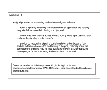
By way of example, Figure 2 shows apparatus 10 having a signal processor
or processing module 10a for implementing the basic signal processing
functionality
according to some embodiments of the present invention. The signal processor
or
processing module 10a may be configured at least to:
receive signaling containing information about an application of a
rotating magnetic field across a fluid flowing in a pipe; and
determine a flow analysis across the fluid flowing in the pipe, based at
least partly on the signaling received.
The signal processor or processing module 10a may also be configured to
provide corresponding signaling containing corresponding information about the
flow
analysis across the fluid flowing in the pipe; and this signaling may be used
by
another device, e.g., for displaying, printing out, or further processing the
flow
analysis determined. The scope of the invention is not intended to be limited
to the
type or kind of use of the corresponding signaling containing information
about the
flow analysis of the fluid flowing in the pipe, including types or kinds of
uses either
now known or later developed in the future.
Further, the scope of the invention is not intended to be limited to the type
or
kind of container, piping or apparatus in which the fluid may be placed or
flowing.
For example, the scope of the invention is intended to include, and
embodiments are
envisioned in which, the signaling received contains information about an
application
8
CA 2882286 2018-06-19
of a rotating magnetic field across a fluid placed, contained or flowing in a
pipe, tank,
cell or vessel.
Furthermore, the scope of the invention is not intended to be limited to the
type or kind of fluid contained, processed or flowing in the pipe. For
example, the
scope of the invention is intended to include processing fluids that are
either now
known or later developed in the future. Moreover still, the scope of the
invention is
not intended to be limited to the type or kind of industrial process of which
the fluid is
being processed, including a process or processes that is or are either now
known or
later developed in the future.
Furthermore still, the apparatus 10 may also include other circuits,
components or modules 10b to implement the functionality of the signal
processor or
processing module 10a either now known or later developed in the future, e.g.,
including memory modules, input/output modules, data and busing architecture
and
other signal processing circuits, wiring or components, consistent with that
known by
a person skilled in the art, and/or consistent with that set forth herein.
Figure 3a to 3c: The Multi-axis Mag meter
By way of example, Figures 3a to 3c show an implementation of an
embodiment for generating a rotating magnetic field in a multi-axis magmeter,
according to some embodiments of the present invention.
For example, Figure 3a shows a process flow pipe P having the multi-axis
magmeter arranged thereon with two pairs of diametrically opposed magnet
coils,
including magnet coils labeled 1A, 1B, 2A and 2B, configured for providing
orthogonal magnetic fields Bv, Bh, that may form part of some embodiments of
the
present invention.
9
CA 2882286 2018-06-19
Figure 3b shows the process flow pipe P having the multi-axis magmeter
arranged thereon with the two pairs of diametrically opposed magnet coils
labeled
1A, 1B, 2A and 2B, consistent with that shown in Figure 3a, configured for
responding to an application of quadrature drive currents, and providing a
rotating
magnetic field Be (where Be = Bv + Bh), that may form part of some embodiments
of
the present invention.
Figure 3c shows the process flow pipe P having the rotating field magmeter
with the two pairs of diametrically opposed magnet coils labeled 1A, 1B, 2A
and 2B,
consistent with that shown in Figure 3a and 3b, configured for responding to
the
application of quadrature drive currents (e.g., labeled ib sin(wt), ib
cos(wt)), as
shown, and providing the rotating magnetic field Be (where Be = Bv + Bh) with
an
angular rate of w, according to some embodiments of the present invention. The
arrow labeled A indicates the direction of rotation of the magnetic field,
which is
shown by way of example, as being clockwise. In effect, the application of
magnetic
fields via the orthogonal coil pairs allows the effective magnetic vector to
be
rotationally steered, based at least partly on the vector summation: Be = Bh+
B.
By way of example, the application of the quadrature drive currents (e.g.,
using sine and cosine functionality) to the magnetic coils labeled 1A, 1B, 2A
and 2B
allows for the generation of the rotating magnetic field Be, according to some
embodiments of the present invention.
Figure 3d: Multi-Coil Magmeter:
By way of example, Figure 3d shows an implementation of an embodiment for
sensing a rotating magnetic field in a multi-axis magmeter, according to some
embodiments of the present invention.
CA 2882286 2018-06-19
For example, Figure 3d shows a process flow pipe having a multi-axis
magmeter arranged thereon with two pairs of diametrically opposed magnet coils
labeled 1A, 1B, 2A and 2B, consistent with that shown in Figures 3a, 3b and
3c, for
responding to the application of quadrature drive currents (e.g., ib sin(wt),
lb cos(wt)),
and providing the rotating magnetic field Be (e.g. where Be = Bv + Bh) with an
angular
rate of w, as well as multiple pairs of diametrically opposed electrodes
(e.g., el, e2,
e3, e12) for responding to the rotating magnetic field Be, and providing
signaling
containing information about the same, according to some embodiments of the
present invention.
In operation, the application of quadrature drive currents (e.g., using sine
and
cosine functionality) to the orthogonal coil pairs labeled 1A, 1B, 2A and 2B
allows for
the generation of the rotating magnetic field Be of substantially constant
strength and
rotational speed co. Combining the rotating field with the multi-electrode
concept
produces a device that provides for a detailed flow profile analysis. The
rotating
magnetic field produces electric potentials across pairs of electrodes (e.g.,
the 12
electrode examples shown), and each electrode pair "samples" the flow rate for
a
particular "plane" in the flow stream.
Figures 4a to 4d
Figure 4a shows a process flow pipe having multiple pairs of electrodes (e.g.,
e2, e3, e12) arranged thereon and configured for sensing in
diametrically
opposed planes (e.g., el - e7; e2 - es; e3 - e9; e4 - eio; e5 - ell; es -
e12), that may form
part of some embodiments of the present invention.
Figure 4b shows a process flow pipe having multiple pairs of electrodes (e.g.,
ei, e2, e3, e12) arranged thereon and configured for sensing in vertical
planes
11
CA 2882286 2018-06-19
(e.g., ei -e7; e2 - es; e3 - es; es - e12; e9 - ell), that may form part of
some
embodiments of the present invention.
Figure 4c shows a process flow pipe having multiple pairs of diametrically
opposed electrodes (e.g., el, e2, e3, e12) arranged thereon and configured
for
sensing in horizontal planes (e.g., e2 - ei; e3 - ell; ea - eio; es - e9; es -
es), that may
form part of some embodiments of the present invention.
Figure 4d shows a process flow pipe having multiple pairs of diametrically
opposed electrodes (e.g., ei, e2, e3, e12) arranged thereon and configured
for
sensing in diametrically-offset planes (e.g., ei - e12; e2 - es - eio; ea -
e9; es - e8;
es - e7), that may form part of some embodiments of the present invention.
Signal Processor or Signal Processing Module 10a
By way of example, and consistent with that described herein, the
functionality
of the signal processor or processing module 10a may be implemented to receive
the signaling, process the signaling, and/or provide the corresponding
signaling,
using hardware, software, firmware, or a combination thereof, although the
scope of
the invention is not intended to be limited to any particular embodiment
thereof. In a
typical software implementation, the signal processor or processing module 10a
may
include, or take the form of, one or more microprocessor-based architectures
having
a microprocessor, a random access memory (RAM), a read only memory (ROM),
input/output devices and control, data and address busing architecture
connecting
the same. A person skilled in the art would be able to program such a
microprocessor-based implementation to perform the functionality set forth
herein, as
well as other functionality described herein without undue experimentation.
The
scope of the invention is not intended to be limited to any particular
implementation
12
CA 2882286 2018-06-19
using technology either now known or later developed in the future. Moreover,
the
scope of the invention is intended to include a signal processor, device or
module
10a as either part of the aforementioned apparatus, as a stand alone module,
or in
the combination with other circuitry for implementing another module.
Techniques for receiving signaling in such a signal processor or processing
module 10a are known in the art, and the scope of the invention is not
intended to be
limited to any particular type or kind thereof either now known or later
developed in
the future. Based on this understanding, a person skilled in the art would
appreciate,
understand and be able to implement and/or adapt the signal processor or
processing module 10a without undue experimentation, e.g., so as to receive
signaling containing information about an application of a rotating magnetic
field
across a fluid flowing in a pipe, tank, cell or vessel, consistent with that
set forth
herein.
Techniques, including techniques based on tomography or tomographic
processing techniques, for determining information based on analyzing or
processing
signaling received in such a signal processor or processing module 10a are
also
known in the art, and the scope of the invention is not intended to be limited
to any
particular type or kind thereof either now known or later developed in the
future.
Based on this understanding, a person skilled in the art would appreciate,
understand and be able to implement and/or adapt the signal processor or
processing module 10a without undue experimentation to determine a flow
analysis
across the fluid flowing in the pipe, tank, cell or vessel, based at least
partly on the
signaling received, e.g., using a tomographic processing technique, consistent
with
that set forth herein.
13
CA 2882286 2018-06-19
It is also understood that the apparatus 10 may include one or more other
modules, components, processing circuits, or circuitry 10b for implementing
other
functionality associated with the underlying apparatus that do not form part
of the
underlying invention, and thus is not described in detail herein. By way of
example,
the one or more other modules, components, processing circuits, or circuitry
may
include random access memory, read only memory, input/output circuitry and
data
and address buses for use in relation to implementing the signal processing
functionality of the signal processor, or devices or components, etc.
Tomography or Tomographic Processing Techniques
Tomography or tomographic processing techniques, e.g., including modulated
magnetic-electrical impedance tomography, are known in the art, and generally
understood to refer to imaging by sections or sectioning, through the use of
some
kind of penetrating wave. A device used in tomography is called a tomograph,
while
the image produced is a tomogram. Such methods or techniques may be used,
e.g.,
in radiology, archeology, biology, geophysics, oceanography, materials
science,
astrophysics, quantum information and other sciences. In most cases, such
methods or techniques may be based on the mathematical procedure called
tomographic reconstruction. Tomographic reconstruction algorithms are known in
the art for determining the imaging by sections or sectioning, through the use
of any
kind of penetrating wave. By way of example, the reader is referred to U.S.
Patent
Nos. 6,078,397; 5,181,778; 4,386,854; and 4,328,707, which all relate to
tomographic techniques. The scope of the invention is not intended to be
limited to
the type or kind of tomographic reconstruction algorithms, e.g., including
those
14
CA 2882286 2018-06-19
based at least partly on using ultrasonic waves, either now known or later
developed
in the future.
By way of example, see also the aforementioned PCT applications referred to,
including PCT application no. PCT/US12/52074 (712-2.358-1 (CCS-0069W0), filed
23 August 2012, as well as PCT application no. PCT/US12/60811 (712-2.363-1
(CCS-0068/70/62W0), filed 18 October 2012, which disclose applications based
at
least partly on using a tomography or tomographic processing technique, which
were
developed and is owned by the assignee of the instant patent application.
Moreover, embodiments are envisioned, and the scope of the invention is
intended to include, using other types or kinds of tomography or tomographic
processing technique either now known or later developed in the future.
Finally, the
scope of the invention is not intended to be limited to any particular type or
kind of
tomography or tomographic processing technique either now known or later
developed in the future.
A person skilled in the art without undue experimentation would be able to
adapt one or more of the aforementioned tomography or tomographic processing
technique in order to implement the present invention, including to configure
a signal
processing module at least to receive signaling containing information about
an
application of a rotating magnetic field across a fluid flowing in a pipe,
tank, cell or
vessel; and determine a flow analysis across the fluid flowing in the pipe,
tank, cell or
vessel, based at least partly on the signaling received.
CA 2882286 2018-06-19
Magnetic Coils and Electrodes
Magnetic coils and electrodes like those shown in the drawing of the present
application herein are known in the art, and the scope of the invention is not
intended
to be limited to any particular type or kind thereof either now known or later
developed in the future.
Moreover, techniques for coupling or arranging such magnetic coils and
electrodes, e.g., to, or in relation to, a pipe, tank, cell or container are
known in the
art, and the scope of the invention is not intended to be limited to any
particular
manner of way of so coupling or arranging the same, e.g., including manners
and
ways either now known or later developed in the future.
Applications
By way of example, the present invention may be used in, or form part of, or
used in conjunction with, industrial processes like a mineral extraction
processing
system for extracting or separating minerals in a fluidic medium that are
either now
known or later developed in the future, including any mineral process, such as
those
related to processing substances or compounds that result from inorganic
processes
of nature andfor that are mined from the ground, as well as including either
other
extraction processing systems or other industrial processes, where the
extraction, or
separating, or sorting, or classification, of product by size, or density, or
some
electrical characteristic, is critical to overall industrial process
performance.
16
CA 2882286 2018-06-19
The Scope of the Invention
While the invention has been described with reference to an exemplary
embodiment, it will be understood by those skilled in the art that various
changes
may be made and equivalents may be substituted for elements thereof without
departing from the scope of the invention. In addition, may modifications may
be
made to adapt a particular situation or material to the teachings of the
invention
without departing from the essential scope thereof. Therefore, it is intended
that the
invention not be limited to the particular embodiment(s) disclosed herein as
the best
mode contemplated for carrying out this invention.
17
CA 2882286 2018-06-19