Note: Descriptions are shown in the official language in which they were submitted.
CA 02882605 2015-08-31
-1-
Heat exchanger for cooling a switch cabinet and
corresponding cooling arrangement
The invention relates to a heat exchanger for cooling a
switch cabinet and to a corresponding cooling
arrangement. A generic heat exchanger has a first line
system for a first coolant and a second line system,
separated fluidically from the first line system, for a
second coolant, the first and the second line system
being coupled thermally to one another for heat
exchange.
A printing machine assembly cabinet which has a heat
exchanger with the above-mentioned features is known
from DE 200 08 411 Ul. Similar heat exchangers are also
described in DE 10 2007 054 724 Al, in
DE 10 2008 059 023 Al, in US 6,053,238 A and in
US 6,039,111 A.
A persistent problem in switch cabinet cooling is that
the ambient temperatures of the switch cabinet over the
course of the year and also the power losses and
accompanying waste heat of the components accommodated
in the switch cabinet may be exposed to pronounced
fluctuations, while, independently of these
fluctuations, the air temperature prevailing in the
switch cabinet interior has to be kept below a specific
value, in order to avoid the situation where the
components accommodated in the switch cabinet are
damaged. The cooling apparatuses used for switch
cabinet cooling, whether they be passive or active
apparatuses, always have, however, a narrow cooling
capacity range within which they can operate in an
energy-efficient way. For example, compressor-driven
cooling apparatuses work in the most energy-efficient
way in continuous operation. However, the maximum
cooling capacity of the compressor-driven cooling
circuit which can be achieved in continuous operation
has to be adapted to maximum ambient temperatures and
CA 02882605 2015-02-20
- 2 -
maximum power losses of the components accommodated in
the switch cabinet, so that sufficient cooling can be
ensured even in extreme situations. As a result of
this, the compressor-driven cooling circuit always runs
in on/off operation over the course of the year, with
the corresponding disadvantages with regard to energy
consumption.
In principle, to increase the energy efficiency of the
cooling apparatus, it is desirable to keep the time
duration in which the compressor-driven cooling circuit
is in operation as short as possible.
In order to address this problem, combined cooling
apparatuses are known from the prior art, which have in
addition to an active cooling circuit, such as a
compressor-driven cooling circuit or a cold water set,
a passive cooling circuit or a passive cooling element,
for example in the form of an air/air heat exchanger.
Such cooling apparatuses are also designated later on
in the application as "hybrid cooling apparatuses".
Active cooling circuits have a refrigerating machine or
a cold water set, introduce the cold into the system
and serve, as a rule, for cooling a cooling medium. The
refrigerating machine may have, for example, a
compressor. The cold water set may in the simplest case
have a cold water reservoir, and in this context a
person skilled in the art would understand that "water"
in cooling applications is not to be interpreted
restrictively, but is used merely as a synonym for the
coolants or refrigerants known from the prior art,
generally designated as "cooling medium". Passive
cooling circuits accordingly have no refrigerating
machine or cold water source. Active cooling of a
cooling medium does not take place.
These cooling apparatuses are designed in such a way
that the necessary cooling of the switch cabinet
interior can be provided solely in a passive way via
CA 02882605 2015-08-31
- 3 -
the air/air heat exchanger over as broad an ambient
temperature range of the switch cabinet as possible and
for the highest possible power losses of the components
accommodated in the switch cabinet, so that the active
cooling circuit, that is to say, for example, the
compressor-driven cooling circuit, has to be put into
operation as backup only when the cooling capacity
achievable with the aid of the air/air heat exchanger
is not sufficient.
Due to the fact that the structural set-up of a cooling
apparatus based on an air/air heat exchanger differs
fundamentally from that of a cooling apparatus based on
a compressor-driven cooling circuit, in the cooling
apparatuses known from the prior art it has not been
possible hitherto, or has been possible only at high
outlay, for the cooling circuit based on the air/air
heat exchanger to be operated in parallel with the
compressor-driven cooling circuit. Furthermore, in the
known cooling apparatuses, to change over between the
cooling processes mentioned, it is always necessary for
structural changes to have to be carried out inside the
cooling apparatus. For example, air routing has to be
adapted to the desired cooling process by altering the
pivoting of flaps and the like. This requires
corresponding actuating mechanisms and the use of
servomotors which reduce the reliability of the system
and increase its complexity. This is critical
especially in light of the fact that the failure of the
cooling apparatus may cause the system composed of
electronic components and accommodated in the switch
cabinet interior to fail or even to be destroyed.
An object of the invention, therefore, is to provide a
heat exchanger for cooling a switch cabinet and a
corresponding switch cabinet, which ensure the energy-
efficient and reliable cooling of the switch cabinet,
while, furthermore, these should allow the especially
flexible adaptation of the cooling apparatus to the
CA 02882605 2015-08-31
-4-
individual conditions, such as the power loss of the switch
cabinet components and the ambient temperature of the
switch cabinet.
This object is achieved, according to the invention, by
means of a heat exchanger having the features described
herein.
According to an aspect of the present invention, there is
provided a heat exchanger for cooling a switch cabinet,
with a first line system for a first coolant and with at
least one second line system, separated fluidically from
the first line system, for a second coolant, the first and
the second line system being coupled thermally to one
another, characterized in that the heat exchanger has a
plurality of lamellae, adjacent lamellae forming between
them an air flow duct through the heat exchanger, and the
first and the second line system being coupled thermally to
one another via the plurality of lamellae.
According to another aspect of the invention, there can be
provided the heat exchanger described herein, in which the
lamellae are oriented parallel to one another.
According to another aspect of the invention, there can be
provided the heat exchanger described herein, in which the
first and the second line system are disposed directly or
indirectly one behind the other in the air flow direction
through the heat exchanger.
According to another aspect of the invention, there can be
provided the heat exchanger described herein, in which the
first and the second line system have in each case a
connection for a coolant forward flow and a connection for
a coolant return flow.
CA 02882605 2015-08-31
-4a-
According to another aspect of the invention, there can be
provided the heat exchanger described herein, in which at
least one of the line systems is routed in a meander-shaped
manner, so that the formation of siphons is prevented.
According to another aspect of the present invention, there
is provided a cooling arrangement with a switch cabinet and
with a cooling apparatus which has a first and a second
heat exchanger as described herein, the first heat
exchanger being disposed in a first air passage with a first
air inlet and with a first air outlet, which are open to
the surroundings of the switch cabinet, and the second heat
exchanger being disposed in a second air passage with a
second air inlet and with a second air outlet, which are
open to an interior of the switch cabinet, the first line
system of the first heat exchanger forming with the first
line system of the second heat exchanger a first closed
coolant circuit, and the second line system of the first
heat exchanger forming with the second line system of the
second heat exchanger a second closed coolant circuit.
According to another aspect of the present invention, there
can be provided the cooling arrangement described herein,
in which the first heat exchanger is disposed at least
partially above the second heat exchanger, at least one of
the two coolant circuits being a passive circuit.
According to another aspect of the present invention, there
can be provided the cooling arrangement described herein,
in which one of the two coolant circuits is a passive
coolant circuit and the other an active coolant circuit,
the first heat exchanger being disposed in the first air
passage and the second heat exchanger being disposed in the
second air passage, in such a way that the line system of
the passive coolant circuit is disposed upstream of the
line system of the active coolant circuit in the air flow
direction.
CA 02882605 2015-08-31
-4b-
According to another aspect of the present invention, there
is provided a cooling arrangement with a switch cabinet and
with a cooling apparatus which has a first and a second
heat exchanger as described herein, the first heat
exchanger being disposed in a first air passage with a first
air inlet and with a first air outlet, which are open to
the surroundings of the switch cabinet, and the second heat
exchanger being disposed in a second air passage with a
second air inlet and with a second air outlet, which are
open to an interior of the switch cabinet, in which either
1. the first and the second line system of the first
heat exchanger are connected in series, the
series-connected line systems forming either
with the first or with the second line system of
the second heat exchanger a closed coolant
circuit, and a coolant flowing through that line
system of the second heat exchanger which is not
an integral part of the closed coolant circuit;
or
2. the first and the second line system of the
second heat exchanger are connected in series,
the series-connected line systems forming either
with the first or with the second line system of
the first heat exchanger a closed coolant
circuit, and a coolant flowing through that line
system of the first heat exchanger which is not
an integral part of the closed coolant circuit.
According to another aspect of the present invention, there
can be provided the cooling arrangement described herein,
in which the first heat exchanger is disposed at least
partially above the second heat exchanger, the closed
coolant circuit being a passive coolant circuit and the
line system through which the coolant flows being an
integral part of an active, preferably pump- or compressor-
driven cooling circuit.
CA 02882605 2015-08-31
-4c-
According to another aspect of the present invention, there
can be provided the cooling arrangement described herein,
in which the heat exchanger which has the line system
through which the coolant flows is an evaporator or an
air/water heat exchanger of the active cooling circuit and
at the same time, when the line system through which the
coolant flows is an integral part of the first heat
exchanger, is a condenser of the passive cooling circuit
or, when the line system through which the coolant flows
is an integral part of the second heat exchanger, is an
evaporator of the passive cooling circuit.
According to another aspect of the present invention, there
can be provided the cooling arrangement described herein,
in which one of the two coolant circuits is a passive
coolant circuit and the other is a compressor-driven
coolant circuit, a compressor and an expansion means of the
active coolant circuit in each case either being bridged
via a selectively openable and closable bypass line or being
capable of assuming a state in which a coolant can pass
through them with insignificant or essentially without
pressure loss.
According to another aspect of the present invention, there
is provided a heat exchanger for cooling a switch cabinet,
with a first line system for a first coolant and with at
least one second line system, separated fluidically from
the first line system, for a second coolant, the first and
the second line systems being coupled thermally to one
another, wherein the heat exchanger has a plurality of
lamellae, adjacent lamellae forming between them an air
flow duct through the heat exchanger, and the first line
system and the at least one second line system being coupled
thermally to one another via the plurality of lamellae.
According to another aspect of the present invention, there
is provided a cooling system with a switch cabinet and with
a cooling apparatus which has a first and a second heat
exchanger as described herein, the first heat exchanger
CA 02882605 2015-08-31
-4d-
being disposed in a first air passage with a first air inlet
and with a first air outlet, which are open to the
surroundings of the switch cabinet, and the second heat
exchanger being disposed in a second air passage with a
second air inlet and with a second air outlet, which are
open to an interior of the switch cabinet, wherein the first
line system of the first heat exchanger forms with the first
line system of the second heat exchanger a first closed
coolant circuit, and the at least one second line system
of the first heat exchanger forming with the at least one
second line system of the second heat exchanger a second
closed coolant circuit.
According to another aspect of the present invention, there
is provided a cooling system with a switch cabinet and with
a cooling apparatus which has a first and a second heat
exchanger as described herein, the first heat exchanger
being disposed in a first air passage with a first air inlet
and with a first air outlet, which are open to the
surroundings of the switch cabinet, and the second heat
exchanger being disposed in a second air passage with a
second air inlet and with a second air outlet, which are
open to an interior of the switch cabinet, wherein
the first line system and the at least one second line
system of the first heat exchanger are connected in series,
the series-connected line systems forming with the first
line system or with the at least one second line system of
the second heat exchanger a closed coolant circuit, and a
coolant flowing through the line system of the second heat
exchanger which is not an integral part of the closed
coolant circuit; or
the first line system and the at least one second line
system of the second heat exchanger are connected in series,
the series-connected line systems forming with the first
line system or with the at least one second line system of
the first heat exchanger a closed coolant circuit, and a
coolant flowing through the line system of the first heat
exchanger which is not an integral part of the closed
coolant circuit.
-4e-
According to another aspect of the present invention there
is provided a cooling arrangement with a switch cabinet and
with a cooling apparatus, which has a first and second heat
exchanger for cooling the switch cabinet, with a first line
system for a first coolant and with at least one second line
system for a second coolant, separated fluidically from the
first line system, wherein the first and the second line
system are coupled thermally to one another, wherein the
heat exchanger comprises a plurality of lamellae, and
adjacent lamellae form between them an air flow duct through
the heat exchanger, and the first and second line system are
coupled thermally to one another via the plurality of
lamellae,
wherein the first heat exchanger is disposed in a first
air passage with a first air inlet and with a first air
outlet, which are open to the surroundings of the switch
cabinet,
wherein the second heat exchanger is disposed in a
second air passage with a second air inlet and with a second
air outlet, which are open to an interior of the switch
cabinet,
wherein the first line system of the first heat
exchanger forms with the first line system of the second
heat exchanger a first closed coolant circuit,
wherein the second line system of the first heat
exchanger forms with the second line system of the second
heat exchanger a second closed coolant circuit, and
wherein one of the cooling circuits is an active
coolant circuit and the other coolant circuit is a passive
coolant circuit.
According to another aspect of the present invention there
is provided a cooling arrangement with a switch cabinet and
with a cooling apparatus which has a first and second heat
exchanger for cooling the switch cabinet, with a first line
system for a first coolant and with at least one second line
CA 2882605 2018-09-27
-4f-
system for a second coolant, separated fluidically from the
first line system, wherein the first and the second line
system are coupled thermally to one another, wherein the
heat exchanger comprises a plurality of lamellae, and
adjacent lamellae form between them an air flow duct through
the heat exchanger, and the first and second line system are
coupled thermally to one another via the plurality of
lamellae,
wherein the first heat exchanger is disposed in a first
air passage with a first air inlet and with a first air
outlet, which are open to the surroundings of the switch
cabinet,
wherein the second heat exchanger is disposed in a
second air passage with a second air inlet and with a second
air outlet, which are open to an interior of the switch
cabinet, in which either:
(i) the first and the second line system of the first
heat exchanger are connected in series, the series-connected
line systems form either with the first or with the second
line system of the second heat exchanger a closed coolant
circuit, and a coolant is able to flow through that line
system of the second heat exchanger which is not an integral
part of the closed coolant circuit; or
(ii) the first and second line system of the second
heat exchanger are connected in series, the series-connected
line systems form either with the first or with the second
line system of the first heat exchanger a closed coolant
circuit, and a coolant is able to flow through that line
system of the first heat exchanger which is not an integral
part of the closed coolant circuit;
wherein the closed coolant circuit is a passive coolant
circuit and the line system through which the coolant is
able to flow is an active cooling circuit.
CA 2882605 2018-09-27
-4g-
According to the invention, the heat exchanger has a
plurality of lamellae oriented preferably parallel to
one another, adjacent lamellae forming between them an
air flow duct through the heat exchanger, and the firs':
and the second line system being coupled thermally to
one another via the plurality of lamellae for heat
exchange. The lamellae serve for coupling thermally to
one another the line systems of the heat exchanger
which are basically formed independently of one
another, in particular are separated fluidically from
one another, so that there is heat exchange between the
first and the second line system whenever the
temperature difference between the coolants held in
reserve in the two line systems is unequal to zero.
The heat exchanger according to the invention is
therefore, in principle, an air-cooled lamellar heat
exchanger which allows heat exchange between the air
flowing through it and a coolant of the first line
system and/or a further coolant of the second line
system. One of the line systems may in this case be,
for example, an integral part of an active cooling
process, for example an integral part of a compressor-
driven cooling circuit, while the other line system is
75 incorporated, for example, into a passive cooling
circuit. The heat exchanger according to the invention
is also distinguished precisely in that it affords high
variability in terms of the implemented cooling process
CA 2882605 2018-09-27
CA 02882605 2015-02-20
- 5 -
when it is used for setting up a cooling apparatus for
switch cabinet cooling. In principle, however, the heat
exchanger according to the invention is not restricted
to switch cabinet cooling applications, but on the
contrary it may be used in the most diverse possible
industrial cooling applications or else for domestic
purposes.
Preferably, the first and the second line system are
disposed one behind the other in the air flow direction
through the heat exchanger. If one of the two line
systems is an integral part of a passive cooling system
and the other line system is an integral part of an
active cooling system, it is expedient that the line
system of the passive cooling circuit is disposed
upstream of the line system of the active cooling
circuit in the air flow direction.
The heat exchanger according to the invention should be
a modular component which can serve in one and the same
embodiment for the configuration of the most diverse
possible cooling apparatuses for switch cabinet air
conditioning. In order to allow the flexible
integration of said heat exchanger into a switch
cabinet cooling apparatus, in one embodiment of the
invention there is provision whereby the first and the
second line system have in each case a connection for a
coolant forward flow and a connection for a coolant
return flow.
The switch cabinet according to the invention comprises
a cooling apparatus which has a first and a second heat
exchanger of the abovementioned type, the first heat
exchanger being disposed in a first air passage with a
first air inlet and with a first air outlet, which are
open to the surroundings of the switch cabinet, and the
second heat exchanger being disposed in a second air
passage with a second air inlet and with a second air
outlet, which are open to an interior of the switch
CA 02882605 2015-02-20
- 6 -
cabinet, the first line system of the first heat
exchanger forming with the first line system of the
second heat exchanger a first closed coolant circuit,
and the second line system of the first heat exchanger
forming with the second line system of the second heat
exchanger a second closed coolant circuit.
In one embodiment of the invention, the cooling
apparatus is a wall-mounted cooling apparatus fastened
to a vertical wall of the switch cabinet. In this case,
preferably, the first heat exchanger is disposed at
least partially above the second heat exchanger, at
least one of the two coolant circuits being a passive
circuit. If the heat exchangers are disposed as
described above, and one of the two coolant circuits is
a closed passive circuit, in the case of switch cabinet
temperatures lying above the ambient temperature of the
switch cabinet, when the passive coolant circuit is
filled at least partially with a coolant, the coolant
held in reserve in the passive coolant circuit in the
region of the second heat exchanger will change from
the liquid to the gaseous state of aggregation on
account of the heat of the switch cabinet air, will
rise into the first heat exchanger, will be cooled
there by the cooler ambient air and will therefore
condense, in order thereupon, driven by gravity, to
flow back again into the second heat exchanger.
While the coolant is absorbing heat in the second heat
exchanger upon evaporation, it discharges this same
heat quantity again upon condensation in the first heat
exchanger. The coolant extracts this heat quantity in
the second heat exchanger precisely from the switch
cabinet air flowing through the second heat exchanger
and, upon condensation in the first heat exchanger,
discharges it into the ambient air. A net heat flux
from the second air passage into the first air passage
therefore takes place.
CA 02882605 2015-02-20
7 -
In the preferred embodiment, one of the two coolant
circuits is a passive circuit and the other is an
active circuit, preferably a compressor- or pump-driven
circuit, the first heat exchanger being disposed in the
first air passage and the second heat exchanger in the
second air passage in such a way that the line system
of the passive coolant circuit is disposed upstream of
the line system of the active coolant circuit in the
air flow direction. The active coolant circuit may in
this case be configured in many different ways. It may,
for example, be a compressor circuit, with a
compressor, with a condenser, with an expansion valve
and with an evaporator, the condenser and the
evaporator being provided precisely by the first and
the second heat exchanger. It may, however, also be a
cold water circuit, in which heat transport takes place
via the circulation of a liquid coolant, preferably
water. The liquid coolant flowing through the second
heat exchanger in the second air passage may in this
case be provided with the aid of an external cold water
source or via the first heat exchanger disposed in the
first air passage.
An alternative switch cabinet according to the
invention has a first and a second heat exchanger
according to the invention, once again the first heat
exchanger being disposed in a first air passage with a
first air inlet and with a first air outlet, which are
open to the surroundings of the switch cabinet, and the
second heat exchanger being disposed in a second air
passage with a second air inlet and with a second air
outlet, which are open to an interior of the switch
cabinet, in which case either:
1. the first and the
second line system of the first
heat exchanger are connected in series, the
series-connected line systems forming either with
the first or with the second line system of the
second heat exchanger a closed coolant circuit,
CA 02882605 2015-08-31
- 8 -
and a coolant flowing through that line system of
the second heat exchanger which is not an integral
part of the closed coolant circuit; or
2. the first and the second line system of the second
heat exchanger are connected in series, the
series-connected line systems forming either with
the first or with the second line system of the
first heat exchanger a closed coolant circuit, and
a coolant flowing through that line system of the
first heat exchanger which is not an integral part
of the closed coolant circuit.
In this case, there may be provision whereby the first
heat exchanger is disposed at least partially above the
second heat exchanger, the closed coolant circuit being
a passive circuit, and the line system through which
the coolant flows being an integral part of an active,
preferably pump- or compressor-driven cooling circuit.
In a further embodiment of the invention, the heat
exchanger which has the line system through which the
coolant flows is an evaporator or an air/water heat
exchanger of the active cooling circuit and at the same
time, when the line system through which the coolant
flows is an integral part of the first heat exchanger,
a condenser of the passive cooling circuit or, when the
line system through which the coolant flows is an
integral part of the second heat exchanger, an
evaporator of the passive cooling circuit.
In one embodiment of the invention, one of the coolant
circuits is a passive circuit and the other is a
compressor-driven coolant circuit, a compressor and an
expansion means of the active coolant circuit being in
each case either bridged via a selectively openable and
closable bypass line or being capable of assuming a
state in which a coolant screen can be passed through
substantially without pressure loss. In this embodiment,
CA 02882605 2015-08-31
- 9 -
the hybrid cooling apparatus has four different
operating modes. In a first operating mode, the first
coolant circuit is operated actively and the second
coolant circuit is deactivated. In a second operating
mode, the first coolant circuit is operated passively
and the second coolant circuit is deactivated. In a
third operating mode, the first coolant circuit is
operated actively and the second coolant circuit
passively. In a fourth operating mode, both the first
and the second coolant circuit are operated passively.
The first coolant circuit therefore has to be operated
actively only when the sum of the cooling capacities of
the first and of the second cooling circuit, when the
first coolant circuit is also operated passively in
addition to the second, is not sufficient.
Instead of the bypass lines, there may also be
provision whereby the expansion means or the compressor
can assume a state in which they cause the coolant to
pass through substantially without pressure loss. Thus,
in the case of expansion means which are designed, for
example, as expansion valves with a needle valve, the
valve can be brought into an open position in which the
coolant can pass, substantially unimpeded, through the
expansion valve. It is likewise conceivable that the
compressor either has an integrated bypass line or can
assume an operating position in which the coolant can
pass, unimpeded, through it.
Further details of the invention are explained with
reference to the following figures in which:
figure 1 shows an embodiment of the heat exchanger
according to the invention in which, for
greater clarity, the lamellae have been
partially omitted;
figure 2 shows a diagrammatic cross-sectional view of
a hybrid cooling apparatus for wall mounting,
CA 02882605 2015-02-20
- 10 -
which combines a heat pipe with a compressor-
driven cooling circuit;
figure 3 shows a cooling apparatus according to the
invention which has only a heat pipe;
figure 4 shows a hybrid cooling apparatus according to
the invention which has a cold water set in
the inner circuit;
figure 5 shows a variant of the embodiment according
to figure 4, in which a cold water set is
disposed in the outer circuit;
figure 6 shows a hybrid cooling apparatus for roof
mounting, in which a cold water set is
disposed in the outer circuit;
figure 7 shows a variant of the cooling apparatus
according to figure 6, in which a cold water
set is disposed in the outer circuit; and
figure 8 shows a hybrid cooling apparatus in which the
active cooling circuit can be selectively
switched to passive via bypasses.
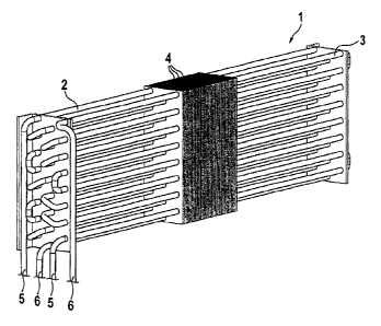
The heat exchanger 1 according to figure 1 has a first
line system 2, in which a first coolant is routed, and
a second line system 3, in which a second coolant is
routed. The line systems 2, 3 are composed in each case
of parallel pipe tracks which extend between two
longitudinal ends of the heat exchanger 1. The parallel
pipelines are connected to one another at the
longitudinal ends in such a way that the coolant is
routed between a respective coolant forward flow 5 and
a coolant return flow 6. The heat exchanger 1
illustrated in figure 1 is designed to have a gas, for
example air, flowing through its longitudinal sides,
vertical in the illustration. The heat exchanger 1 has
CA 02882605 2015-02-20
- 11 -
a plurality of lamellae 4, adjacent lamellae forming
between them in each case an air flow duct through the
heat exchanger. Furthermore, the lamellae 4, which may
also be designed as plates corresponding to a plate
heat exchanger, have the task of coupling the first and
the second line system 2, 3 thermally to one another
for heat exchange. In the above-described flow
direction of the air flowing through the heat exchanger
1, the first and the second line system 2, 3 are
disposed one behind the other in the air flow
direction. If the first line system 2 is an integral
part of a passive cooling circuit and the second line
system 3 is an integral part of an active cooling
circuit, and if, furthermore, there is provision
whereby the cooling of the air flowing through the heat
exchanger 1 preferably takes place via the passive
cooling process, there may be provision whereby the
active cooling process is activated only when the
cooling capacity provided by the passive cooling
circuit is not sufficient. Since the two cooling
circuits are implemented independently of one another,
it is not necessary for the passive cooling circuit to
be interrupted or even completely deactivated in order
to switch on the active cooling circuit. When the
active cooling circuit is deactivated and cooling is
therefore to take place via the passive cooling
circuit, the pipelines of the line system of the active
cooling circuit in the first heat exchanger 1 serve for
increasing the cooling capacity of the line system of
the passive cooling circuit by virtue of the heat
coupling implemented with the aid of the lamellae 4.
Even when the active cooling circuit is thus
deactivated, its line system in the heat exchanger 1 is
not useless. Instead, it serves in this case for
increasing the efficiency of the passive cooling
circuit. When both cooling circuits are activated, heat
transport between the first and the second line system
2, 3 likewise takes place according to a temperature
gradient which is established, as a result of which
CA 02882605 2015-02-20
- 12 -
heat or cold peaks inside the heat exchanger 1 are
avoided, so that, in turn, an increase in the
efficiency of the heat exchanger is achieved.
Figure 2 shows a switch cabinet 7 in which the cooling
apparatus 8 is designed as a wall-mounted cooling
apparatus. The switch cabinet 7 comprises a switch
cabinet interior 7.1, the cooling apparatus 8 being
attached to an outer wall of the switch cabinet 7, and
the interior 7.1 of the switch cabinet 7 being
connected fluidically to the second air passage 12 of
the cooling apparatus 8 via an air inlet 10 and an air
outlet 11. The air received in the switch cabinet 7.1
is transported through the air passage 12 with the aid
of the fan 17. A second heat exchanger 1.2 according to
the invention, as shown in figure 1, is disposed in the
second air passage 12. The cooling apparatus 8 has,
separated fluidically from the second air passage 12, a
first air passage 9 which is connected fluidically to
the surroundings of the switch cabinet 7 via an air
inlet 10 and an air outlet 11. A fan 17 serves, in
turn, for transporting ambient air via the inlet 10
into the first air passage 9 of the cooling apparatus
8. Disposed in the first air passage 9 is a first heat
exchanger 1.1 according to the invention, as shown in
figure 1, through which the air routed through the
first air passage 9 flows. The heat exchangers 1.1, 1.2
are connected fluidically to one another in such a way
that the first line system 2 of the first heat
exchanger 1.1 forms with the first line system 2 of the
second heat exchanger 1.2 a first closed coolant
circuit 13 and the second line system 3 of the first
heat exchanger 1.1 forms with the second line system 3
of the second heat exchanger 1.2 a second closed
coolant circuit 14.
In the embodiment according to figure 2, the first
closed coolant circuit 13 is a compressor-driven
coolant circuit with a compressor 15 and with an
CA 02882605 2015-02-20
- 13 -
expansion valve 16. Consequently, the first heat
exchanger 1.1, insofar as it relates to the first
closed coolant circuit 13, has the function of a
condenser, and the second heat exchanger 1.2, insofar
as it relates to the first closed coolant circuit 13,
has the function of an evaporator.
The second closed coolant circuit 14 forms a passive
cooling circuit. For this purpose, the first heat
exchanger 1.1 is disposed above the second heat
exchanger 1.2. The second closed coolant circuit 14 is
filled at least partially with a coolant. The liquid
coolant settles as a consequence of gravity in the
lower region of the second closed coolant circuit 14.
It is precisely there where the second heat exchanger
1.2 is disposed. The warm switch cabinet air
transported through the second air passage 12 flows
through the second heat exchanger 1.2. In this case,
the coolant of the second closed coolant circuit 14
heats up, whereupon it evaporates at least partially.
The evaporating coolant rises into the first heat
exchanger 1.1. The latter is cooled by the cool ambient
air of the switch cabinet 7 which is transported
through the first air passage 9 with the aid of the fan
17, whereupon the gaseous coolant in the first heat
exchanger 1.1 condenses. The condensed coolant, driven
by gravity, travels out of the first heat exchanger 1.1
back into the lower-lying second heat exchanger 1.2 and
can evaporate once again there and rise into the second
heat exchanger 1.2.
The cooling apparatus 8 according to figure 2 can thus
be operated selectively in three different cooling
modes, to be precise solely active, solely passive or
hybrid, wherein in hybrid operation, in particular,
there may be provision whereby the passive cooling
process is operated permanently, while the active
cooling process serves for supplementing the cooling
capacity provided with the aid of the passive cooling
CA 02882605 2015-08-31
- 14 -
process, to an extent such that, in sum, at least the
required cooling capacity is made available.
Figures 3 to 7 illustrate that substantially one and the
same coo] log apparatus set-up can serve for
implementing a multiplicity of different cooling
processes. In this case, the embodiments according to
figures 3 to 5 relate to wall-mounted cooling
apparatuses and the embodiments according to figures 6
and 7 to cooling apparatuses which are designed as roof
mountings.
The cooling apparatus 8 according to figure 3 has two
heat exchangers 1.1, 1.2 according to the invention, in
which in each case the first and the second line system
2, 3 are connected in series in such a way that the
respective heat exchanger 1.1, 1.2 has in each case a
connection for a coolant forward flow and a connection
for a coolant return flow. The cooling circuit has no
active components, such as compressors, condensers or
pumps, and is therefore based on the heat pipe
principle already described above. For this purpose, in
particular, it is necessary that the first heat
exchanger 1.1 is disposed at least partially above the
second heat exchanger 1.2.
As figure 4 shows, substantially the same set-up of the
cooling apparatus 8 can be used to implement a hybrid
cooling process in which the first and the second line
system 2, 3 of the first heat exchanger 1.1 are
connected in series, these forming with one of the two
line systems 2, 3 of the second heat exchanger 1.2 a
passive closed cooling circuit 13. The remaining line
system 2,3 of the second heat exchanger 1.2 forms with
a cold water source 18 a second closed coolant circuit
14. The cold water source 18 provides cooled water
which is circulated through the heat exchanger 1.2 and
is not an integral part of the cooling apparatus 8.
This additional active coolant circuit 14 may therefore
CA 02882605 2015-02-20
- 15 -
serve, either in the case of high power losses of the
components accommodated in the switch cabinet interior
7.1 or in the case of high ambient temperatures of the
switch cabinet 7, for making available an additional
cooling capacity which supplements the cooling capacity
provided with the aid of the passive cooling circuit
13, to an extent such that, in sum, sufficient switch
cabinet cooling is made available.
Particularly in the case of high ambient temperatures,
it may be expedient, corresponding to the set-up
according to figure 5, to implement the additional
active coolant circuit 14 with the aid of the heat
exchanger 1.1 integrated into the second air passage 9.
Figures 6 and 7 show that cooling apparatus 8 for roof
mounting, which have the high variability according to
the invention, can be implemented in a similar way to
figures 3 and 4. Even where cooling apparatuses
implemented as roof mountings are concerned, the user
is free to implement the active coolant circuit 14, in
addition to the passive coolant circuit 13, either in
the outer circuit via the first heat exchanger 1.1 (see
figure 6) or in the inner circuit via the second heat
exchanger 1.2 (see figure 7).
Figure 8 describes an alternative embodiment of the
hybrid cooling apparatus 8 according to the invention,
with a first and a second heat exchanger 1 according to
the invention which couple a first closed coolant
circuit 13 and a second closed coolant circuit 14
thermally to one another. The first closed coolant
circuit 13 is an active coolant circuit which has one
behind the other in the coolant flow direction a
compressor 15, a condenser in the form of the upper
heat exchanger 1, an expansion means 16 and an
evaporator in the form of the lower heat exchanger 1.
The compressor 15 and the expansion means 16 are
bridged via a bypass line 19 which has in each case a
CA 02882605 2015-02-20
- 16 -
valve 20. In the closing position of the valves 20, the
first closed coolant circuit 13 can be operated
actively. When the valves 20 are opened, the heat
exchangers 1 form a heat pipe and therefore a passive
coolant circuit. The two coolant circuits 13, 14 are
disposed in relation to one another in such a way that
the respective refrigerants are transported in the
opposite direction to one another when the first
coolant circuit 13 is operated actively. A second
coolant is routed in the second coolant circuit 14
between the evaporator and the condenser. The condenser
and the evaporator are in each case configured in such
a way that the two coolant circuits 13, 14 are coupled
thermally to one another via the evaporator and the
condenser. The condenser is disposed at a vertical
distance above the evaporator. The condenser is
disposed in a first air passage 9, formed by a first
sub-housing of the cooling apparatus, of the cooling
apparatus 8 and the evaporator and also the compressor
15 and the expansion means 16 are disposed in a second
air passage 12, formed by a second sub-housing of the
cooling apparatus. Ambient air of the switch cabinet is
transported through the first air passage 9 and, in
particular, the condenser with the aid of a fan 17.
Heated air from the switch cabinet interior is
transported through the second air passage 12 and, in
particular, the evaporator with the aid of a further
fan 17. The valves 20 in the bypass lines 19 are
preferably electrically activatable solenoid valves.
The second coolant in the second coolant circuit 14 is
heated via the warm switch cabinet air transported
through the second air passage 12, whereupon said
second coolant evaporates at least partially or reduces
its density at least to an extent such that it is
transported along the second coolant circuit 14 from
the evaporator into the condenser. Cool ambient air of
the switch cabinet flows around the condenser. The
coolant thereby condenses or is compressed in such a
CA 02882605 2015-02-20
- 17 -
way that it flows along the coolant circuit 14 back
into the evaporator, in order to be heated once again
there by the warm switch cabinet air. If the first
coolant circuit 13 is likewise in the passive operating
mode, even in this, the refrigerant can circulate
between the evaporator and the condenser in the way
described above with reference to the second coolant
circuit 14. In this case, the transport direction of
the first coolant in the first coolant circuit 13 is
opposite to the depicted flow direction x. The depicted
flow direction x of the first coolant in the first
coolant circuit 13 corresponds to that which occurs
during the active operation of the first coolant
circuit 13. In this case, the coolants in the first and
the second coolant circuit 13, 14 thus move in opposite
directions, with the result that the efficiency of the
evaporator and of the condenser is further improved.