Note: Descriptions are shown in the official language in which they were submitted.
CA 02882775 2015-02-23
WO 2014/033131 PCT/EP2013/067730
Apparatus and Method for Reproducing an Audio Signal, Apparatus and Method for
Generating a Coded Audio Signal, Computer Program and Coded Audio Signal
Description
The present invention relates to an apparatus, a method and a computer program
for
reproducing an audio signal and, in particular, to an apparatus, a method and
a computer
program for reproducing an audio signal in situations in which the available
data rate is
reduced. In addition, the present invention relates to an apparatus, a method
and a
computer program for generating a coded audio signal and a corresponding coded
audio
signal.
The perceptually adapted encoding of audio signals, for efficient storage and
transmission
of these data rate reduced signals, has gained acceptance in many fields.
Encoding
algorithms are known, in particular as MPEG-1/2, layer 3 "MP3", MPEG-2/4
Advanced
Audio Coding (AAC) or MPEG-H Unified Speech and Audio Coding (USAC). The
underlying coding techniques, in particular when achieving lowest bit rates,
lead to a
reduction of the audio quality. The impairment is often mainly caused by an
encoder side
limitation of the audio signal bandwidth to be transmitted.
In such a situation, it is known state-of-the-art to subject the audio signal
to a band limiting
on the encoder side, and to encode only a lower band of the audio signal by
means of a
high quality audio encoder. The upper band, however, is only very coarsely
characterized
by a set of parameters, which convey e.g. the spectral envelope of the upper
band. On the
decoder side, the upper band is then synthesized by patching the decoded lower
band
signal into the otherwise empty upper band and performing subsequent parameter
controlled adjustments.
Standard methods for a bandwidth extension of band-limited audio signals use a
copying
function of low-frequency signal portions (LF) into the high frequency range
(HF), in order
to approximate information missing due to the band limitation. In principle,
such a
copying function is technically equivalent to a spectral shift computed in
time domain by
means of single sideband (SSB) modulation, but computationally much less
complex. Such
methods, like Spectral Band Replication (SBR), are described in M. Dietz, L.
Liljeryd, K.
Kjorling and 0. Kunz, "Spectral Band Replication, a novel approach in audio
coding," in
112th AES Convention, Munich, May 2002; S. Meltzer, R. Bohm and F. Henn, "SBR
enhanced audio codecs for digital broadcasting such as "Digital Radio
Mondiale" (DRM),"
CA 02882775 2015-02-23
2
WO 2014/033131 PCT/EP2013/067730
112th AES Convention, Munich, May 2002; T. Ziegler, A. Ehret, P. Ekstrand and
M.
Lutzky, "Enhancing mp3 with SBR: Features and Capabilities of the new mp3PRO
Algorithm," in 112th AES Convention, Munich, May 2002; International Standard
ISO/IEC 14496-3:2001/FPDAM 1, "Bandwidth Extension," ISO/IEC, 2002, or "Speech
bandwidth extension method and apparatus", Vasu Iyengar et al. US Patent Nr.
5,455,888.
In these methods no harmonic transposition is performed, but successive
bandpass signals
of the lower band are introduced into successive filterbank channels of the
upper band. By
this, a coarse approximation of the upper band of the audio signal is
achieved. This coarse
approximation of the signal is then in a further step approximated to the
original by a post
processing using control information gained from the original signal. Here,
e.g. scale
factors serve for adapting the spectral envelope, an inverse filtering and the
addition of a
noise floor for adapting tonality and a supplementation by sinusoidal signal
portions, as it
is also described in the MPEG-4 Standard.
It is known from harmonic bandwidth extensions techniques described in Nagel,
F.; Disch,
S. A Harmonic Bandwidth Extension Method for Audio Codecs, IEEE Int. Conf. on
Acoustics, Speech and Signal Processing (ICASSP), 2009; Nagel, F.; Disch, S.;
Rettelbach, N. A Phase Vocoder Driven Bandwidth Extension Method with Novel
Transient Handling for Audio Codecs, 126th AES Convention, 2009; Zhong, H.;
Villemoes, L.; Ekstrand, P. et al. QMF Based Harmonic Spectral Band
Replication, 131st
Audio Engineering Society Convention, 2011; Villemoes, L.; Ekstrand, P.;
Hedelin, P.
Methods for enhanced harmonic transposition, IEEE Workshop on Applications of
Signal
Processing to Audio and Acoustics, (WASPAA), 2011, that in synthesizing the
upper band
unwanted auditory roughness might be introduced into the signal. One cause
(out of many)
of said roughness is spectral misalignment of the patch and/or dissonance
effects in the
transition regions between lower band and first patch or between consecutive
patches.
Harmonic bandwidth extensions techniques are designed to improve on these two
aspects,
albeit at the expense of computational complexity.
Filterbank calculations and patching in the filterbank domain, especially in
harmonic
bandwidth extension, may indeed become a high computational effort. In WO
98/57436 an
advanced patching technique is described which can, to some limited extent,
avoid
dissonance effects by introducing so-called guard bands between different
spectral patches
and by performing a modified copy-up patching to lessen spectral misalignment
while
keeping computational complexity moderate.
CA 02882775 2015-02-23
3
WO 2014/033131 PCT/EP2013/067730
Apart from this, further methods exist such as the so-called "blind bandwidth
extension",
described in E. Larsen, R.M. Aarts, and M. Danessis, "Efficient high-frequency
bandwidth
extension of music and speech", In AES 112th Convention, Munich, Germany, May
2002
wherein no information on the original HF range is used. Further, also the
method of the
so-called "Artificial bandwidth extension", exists which is described in K.
Kayhko, A
Robust Wideband Enhancement for Narrowband Speech Signal; Research Report,
Helsinki
University of Technology, Laboratory of Acoustics and Audio signal Processing,
2001.
In J. Makinen et al.: AMR-WB+: a new audio coding standard for 3rd generation
mobile
audio services Broadcasts, IEEE, ICASSP '05, a method for bandwidth extension
is
described, wherein the copying operation of the bandwidth extension with an up-
copying
of successive bandpass signals according to SBR technology is replaced by
mirroring, for
example, by upsampling.
Further technologies for bandwidth extension are described in the following
documents.
R.M. Aarts, E. Larsen, and 0. Ouweltjes, "A unified approach to low- and high
frequency
bandwidth extension", AES 115th Convention, New York, USA, October 2003; E.
Larsen
and R.M. Aarts, "Audio Bandwidth Extension ¨ Application to psychoacoustics,
Signal
Processing and Loudspeaker Design", John Wiley & Sons, Ltd., 2004; E. Larsen,
R.M.
Aarts, and M. Danessis, "Efficient high-frequency bandwidth extension of music
and
speech", AES 112th Convention, Munich, May 2002; J. Makhoul, "Spectral
Analysis of
Speech by Linear Prediction", IEEE Transactions on Audio and Electroacoustics,
AU-
21(3), June 1973; United States Patent Application 08/951,029; United States
Patent No.
6,895,375.
Known methods of harmonic bandwidth extension show a high complexity. On the
other
hand, methods of complexity-reduced bandwidth extension show quality losses.
In
particular with a low bitrate and in combination with a low bandwidth of the
LF range,
artifacts such as roughness and a timbre perceived to be unpleasant may occur.
A reason
for this is primarily the fact that the approximated HF portion is based on
one or more
direct copy or mirror operations of the LF portion of the spectrum.
It is the object of the invention to provide for an apparatus and a method for
reproducing
an audio signal in an improved manner. Moreover, it is an object of the
invention to
provide for an apparatus and a method for generating a coded audio signal
which may be
reproduced in an improved manner. It is a further object of the invention to
provide for a
corresponding computer program and a corresponding coded audio signal.
CA 02882775 2016-08-16
4
This object is achieved by an apparatus for reproducing an audio signal, a
method for
reproducing an audio signal, an apparatus for generating a coded audio signal,
a method for
generating a coded audio signal, a computer program and a coded audio signal,
as set out
in greater detail herein.
Embodiments of the invention provide for an apparatus for reproducing an audio
signal
based on first data representing a coded version of a first portion of the
audio signal in a
first frequency band and second data representing side information on a second
portion of
the audio signal in a second frequency band, the second frequency band
comprising
frequencies higher than the first frequency band, the device comprising:
a first reproducer configured to reproduce the first portion of the audio
signal based on the
first data;
a provider configured to provide a patch signal in the second frequency band,
wherein the
patch signal is uncorrelated with respect to the first portion of the audio
signal or is a
decorrelated version of the first portion of the audio signal, which has been
shifted to the
second frequency band;
a second reproducer configured to reproduce the second portion of the audio
signal in the
second frequency band based on the second data and the patch signal; and
a combiner to combine the reproduced first portion of the audio signal and the
patch signal
before the second portion of the audio signal is reproduced by the second
reproducer or to
combine the reproduced first portion of the audio signal and the reproduced
second portion
of the audio signal.
Embodiments of the invention provide for a method for reproducing an audio
signal based
on first data representing a coded version of a first portion of the audio
signal in a first
frequency band and second data representing side information on a second
portion of the
audio signal in a second frequency band, the second frequency band comprising
frequencies higher than the first frequency band, the method comprising:
reproducing the audio signal in the first frequency band based on the first
data;
providing a patch signal in the second frequency band, wherein the patch
signal is
uncorrelated with respect to the first portion of the audio signal or is a
decorrelated version
CA 02882775 2015-02-23
WO 2014/033131 PCT/EP2013/067730
of the first portion of the audio signal, which has been shifted to the second
frequency
band;
reproducing the audio signal in the second frequency band based on the second
data and
5 the patch signal; and
combining the reproduced first portion of the audio signal and the patch
signal before the
second portion of the audio signal is reproduced or combining the reproduced
first portion
of the audio signal and the reproduced second portion of the audio signal.
Embodiments of the invention relate to a reproduction of an audio signal
providing for a
bandwidth extension using decorrelated sub-band audio signals. In contrast to
already
existing methods, most of the signal distortions and artifacts, which
currently are typical
for bandwidth extensions, may be avoided by using decorrelated sub-band audio
signals
for bandwidth extension, rather than correlated (copied-up or mirrored) sub-
band audio
signals. This is achieved by providing the audio signal, which forms the basis
for a
reproduction of a high-frequency portion of the audio signal, uncorrelated or
decorrelated
with respect to the first portion (LF portion) of the audio signal.
Embodiments of the
invention are based on the recognition that the correlation between the low
frequency
portion and the high frequency portion need not be maintained when reproducing
the
second signal portion of the audio signal. Rather, the inventors recognized
that artifacts,
such as roughness and a timbre perceived to be unpleasant may be avoided by
making use
of a decorrelated or completely uncorrelated patch signal.
Embodiments of the invention provide for an apparatus for generating a coded
audio
signal, the coded audio signal comprising first data representing a coded
version of a first
portion of the audio signal in a first frequency band and second data
representing side
information on a second portion of the audio signal in a second frequency
band, the second
frequency band comprising frequencies higher than the first frequency band,
the apparatus
comprising:
a decorrelation information adder configured to add to the coded audio signal
information
on a degree of decorrelation to be used between the first portion of the audio
signal and a
patch signal based on which the second portion of the audio signal is
reproduced when
reproducing the audio signal from the coded audio signal.
Embodiments of the invention provide for a method for generating a coded audio
signal,
the coded audio signal comprising first data representing a coded version of a
first portion
6
CA 02882775 2015-02-23
WO 2014/033131 PCT/EP2013/067730
of the audio signal in a first frequency band and second data representing
side information
on a second portion of the audio signal in a second frequency band, the second
frequency
band comprising frequencies higher than the first frequency band, the method
comprising:
adding to the coded audio signal information on a degree of decorrelation to
be used
between the first portion of the audio signal and a patch signal based on
which the second
portion of the audio signal is reproduced when reproducing the audio signal
from the coded
audio signal.
Embodiments of the invention provide for a coded audio signal comprising:
first data representing a coded version of a first portion of the audio signal
in a first
frequency band;
second data representing side information on a second portion of the audio
signal in a
second frequency band, the second frequency band comprising frequencies higher
than the
first frequency band; and
information on a degree of decorrelation to be used between the first portion
of the audio
signal and a patch signal based on which the second portion of the audio
signal is
reproduced when reproducing the audio signal from the coded audio signal.
Thus, embodiments of the invention permit for generating a coded audio signal
in a
manner which permits for decoding the coded audio signal in an appropriate
manner using
an appropriate degree of decorrelation. The appropriate degree of
decorrelation may be
determined at the encoder side based on properties of the first portion and/or
the second
portion of the audio signal.
In the following, embodiments of the present invention are explained in more
detail with
reference to the accompanying drawings, in which:
Fig. la shows a block diagram of an embodiment of an apparatus for reproducing
an
audio signal;
Fig. lb shows a block diagram of another embodiment of an apparatus for
reproducing
an audio signal;
CA 02882775 2016-08-16
7
Fig. 2 shows a block diagram of a further embodiment of an apparatus for
reproducing
an audio signal;
Fig. 3 shows a block diagram of an embodiment of an apparatus for
generating a coded
audio signal;
Fig. 4a shows a schematical illustration of an encoder side in the context of
embodiments of the invention;
Fig. 4b shows a schematical illustration of a decoder-side in the context of
embodiments
of the invention;
Figs. 5a and 5b show diagrams illustrating advantages of embodiments of the
invention;
Fig. 6 shows a block diagram of an apparatus for reproducing an audio
signal from
which the invention starts; and
Fig. 7a to 7d show signal diagrams useful in explaining the operation of the
apparatus
shown in Fig. 6.
Prior to explaining embodiments of the invention in detail, it is regarded
worthwhile
shortly discussing theoretical thoughts underlying the invention.
As explained above, bandwidth extensions based on copy operations (or mirror
operations), such as for example SBR (SBR = spectral band replication), copy
large parts
of an LF spectrum directly into the HF range.
An example of an SBR apparatus is described referring to Figs. 6 and 7. The
envelope of
an audio signal 2 is shown in Fig. 7a. Audio signal 2 comprises a low-
frequency portion
(or low-frequency band) 4 and a high-frequency portion (or high-frequency
band) 6.
Typically, in perceptual coding of audio signals, the low-frequency portion 4
is coded by
means of a high quality audio encoder, such as a PCM encoder (PCM = pulse code
modulation), while the upper band is only very coarsely characterized by side
information.
Data representing the coded low-frequency portion and data representing the
side
information are transmitted using a corresponding core codec. Fig. 6 shows a
baseband
signal 8 from a core codec, which represents the low-frequency portion 4 shown
in Fig. 7b.
This signal 8 is applied to a single sideband modulation/copy-up unit 11, in
which signal 8
is shifted to the frequency range of the high-frequency portion 6. This
shifted signal is
shown
CA 02882775 2015-02-23
8
WO 2014/033131 PCT/EP2013/067730
as signal 10 in Fig. 7c. Shifted signal 10 and signal 8 are applied to a
patching unit 12, in
which both signals are combined (added) to obtain the spectrum shown in Fig.
7c. The
signal portion 8 may be shifted into p different higher frequency ranges,
wherein p > 1.
Thus, a combination of one or more (p) shifted signals and signal 8 may take
place in
patching unit 12.
The output signal of patching unit 12 is applied to a post-processing unit 14,
which also
receives side information 16 representing the audio signal in the high-
frequency portion 6.
Thus, the high frequency portion 10' of the audio signal 6 is reproduced based
on the side
information 16 and the audio signal of the low-frequency portion 4. The
resulting audio
signal is shown in Fig. 7d. Post-processing unit 14 outputs the full band
output covering
the frequency ranges of the low-frequency portion 4 and the high-frequency
portion 6.
Accordingly, bandwidth extensions based on copy operations (or mirror
operations), such
as for example SBR, copy large parts of a low-frequency spectrum directly into
the high-
frequency range. This may be achieved by employing a single-sideband
modulation of the
time-domain representation of the audio signal or by a direct copy process
(copy-up) in the
spectral representation of the audio signal. This processing step is usually
called
"patching".
Generally, there may be a plurality of patches copied into different high
frequency bands.
The respective frequency bands may overlap or not. Each of the corresponding
HF patches
thus is completely correlated to the low-frequency range from which it has
been extracted.
The inventors recognized that, thereby, temporal envelope modulations may
occur by
superimposing both signals with a frequency that depends on the spectral
distance between
the LF band and the spectral location of the respective HF patch.
From a system-theoretical point of view, this phenomenon is to be regarded as
dual to the
operation of a finite impulse response (FIR) comb filter comprising a delay of
n samples
with Fs as sample frequency. This filter has a magnitude frequency response
with a comb
width (spectral distance between two maxima of the magnitude frequency
response) of
lin*Fs. Thereby, the system-theoretical duality has the following direct
correspondences:
time delay <-> frequency translation
magnitude frequency response <-> temporal envelope.
The inventors recognized that the temporal modulations resulting therefrom are
audible in
a disturbing manner and can be made visible in the autocorrelation function of
the
CA 02882775 2015-02-23
9
WO 2014/033131 PCT/EP2013/067730
waveform magnitude in the form of periodically repeating side maxima. Such
periodically
repeating side maxima in the autocorrelation sequence of a noise signal
envelope for copy-
up SBR are shown in Fig. 5a. Fig. 5a shows the autocorrelation function of the
magnitude
envelope of white noise, wherein the bandwidth is extended with three direct
copy-up
patches, which are fully correlated among each other and with the LF band.
Only when the LF and the HF signal show the same amplitude, a maximum
modulation
depth is achieved. In practice, the modulation effect therefore is often
slightly lower,
because typically the HF range is markedly quieter (less loud) than the LF
range. Noise-
like signals or quasi-stationary signals with a pronounced overtone structure
are to be
regarded as particularly critical with respect to the modulation artifacts.
For the presence of several patches (p in Fig. 6) that are entirely correlated
among each
other, the above-mentioned duality is valid as well, of course. A temporal
modulation of
the magnitude envelope appears that is dual to the magnitude frequency
response of a
corresponding FIR filter.
Thus, according to embodiments of the invention, the patch or the patches are
decorrelated
from each other and from the LF band. In embodiments of the invention, one or
more
decorrelators are used that decorrelate the signal derived from the low-
frequency signal
components, respectively, before it is inserted into the higher frequency
range(s) and, as
the case may be, post-processed.
Embodiments of the invention avoid the explained problems that occur due to a
copy
operation or a mirror operation by using mutually decorrelated patches. In
embodiments of
the invention, the respective HF patches are decorrelated from the LF band in
an individual
manner using decorrelators, for example by means of all-pass filters or other
known
decorrelation methods, or to create the patches synthetically in a naturally
decorrelated
manner right away.
In embodiments of the invention, the degree of decorrelation can be fixedly
determined or
adjusted at the decoder-side, or it may be transmitted as a parameter from the
encoder to
the decoder. Furthermore, the entire patch may be decorrelated, or only
specific portions of
the patch. The portions of the patch to be decorrelated by also be transmitted
as a
parameter from the encoder to the decoder as part of the corresponding
information added
to the coded audio signal.
CA 02882775 2015-02-23
WO 2014/033131 PCT/EP2013/067730
The inventive approach is beneficial when compared to conventional approaches
for
bandwidth extension since distortions and sound colorations by disturbing or
parasitic
envelope modulations, as they exist with current methods based on single-
sideband
modulation/copy-up of the LF band, are inherently avoided with the inventive
approach.
5 This is achieved by using HF patches that are decorrelated versions of
the LF signal
portion or that are completely uncorrelated with respect to the LF signal
portion.
A scenario in which embodiments of the invention may be implemented is now
described
with reference to Figs. 4a and 4b.
An encoder side is shown in Fig. 4a and a decoder side is shown in Fig. 4b. An
audio
signal is fed into a lowpass/highpass combination at an input 700. The
lowpass/highpass
combination on the one hand includes a lowpass (LP), to generate a lowpass
filtered
version of the audio signal, illustrated at 703 in Fig. 7a. This lowpass
filtered audio signal
is encoded with an audio encoder 704. The audio encoder is, for example, an
MP3 encoder
(MPEG-1/2 layer 3) or an AAC encoder, described in the MPEG-2/4 standard.
Alternative
audio encoders providing a transparent or advantageously perceptually
transparent
representation of the band-limited audio signal 703 may be used in the encoder
704 to
generate a completely encoded or perceptually encoded and perceptually
transparently
encoded audio signal 705, respectively. The upper band of the audio signal is
output at an
output 706 by the highpass portion of the filter 702, designated by "HP". The
highpass
portion of the audio signal, i.e. the upper band or HF band, also designated
as the HF
portion, is supplied to a parameter calculator 707 which is implemented to
calculate the
different parameters (representing side information representing the high
frequency portion
of the audio signal). These parameters are, for example, the spectral envelope
of the upper
band 706 in a relatively coarse resolution, for example, by representation of
a scale factor
for each frequency group on a perceptually adapted scale (critical bands) e.g.
for each Bark
band on the Bark scale. A further parameter which may be calculated by the
parameter
calculator 707 is the noise floor in the upper band, whose energy per band may
be related
to the energy of the envelope in this band. Further parameters which may be
calculated by
the parameter calculator 707 include a tonality measure for each partial band
of the upper
band which indicates how the spectral energy is distributed in a band, i.e.
whether the
spectral energy in the band is distributed relatively uniformly, wherein then
a non-tonal
signal exists in this band, or whether the energy in this band is relatively
strongly
concentrated at a certain location in the band, wherein then rather a tonal
signal exists for
this band. Further parameters consist in explicitly encoding peaks relatively
strongly
protruding in the upper band with regard to their height and their frequency,
as the
bandwidth extension concept, in the reconstruction without such an explicit
encoding of
11
CA 02882775 2015-02-23
WO 2014/033131 PCT/EP2013/067730
prominent sinusoidal portions in the upper band, will only recover the same
very
rudimentarily, or not at all.
In any case, the parameter calculator 707 is implemented to generate only
parameters 708
for the upper band which may be subjected to similar entropy reduction steps
as they may
also be performed in the audio encoder 704 for quantized spectral values, such
as for
example differential encoding, prediction or Huffman encoding, etc. The
parameter
representation 708 and the audio signal 705 are then supplied to a datastream
formatter 709
which is implemented to provide an output side datastream 710 which will
typically be a
bitstream according to a certain format as it is for example normalized in the
MPEG4
Standard.
The decoder side, as it may be suitable for the present invention, is shown in
Fig. 7b. The
datastream 710 enters a datastream interpreter 711 which is implemented to
separate the
parameter portion 708 from the audio signal portion 705. The parameter portion
708 is
decoded by a parameter decoder 712 to obtain decoded parameters 713. In
parallel to this,
the audio signal portion 705 is decoded by an audio decoder 714 to obtain the
audio signal
777 which was illustrated at 8 in Fig. 6, for example.
Depending on the implementation, audio signal 777 may be output via a first
output 715.
At the output 715, an audio signal with a small bandwidth and thus also a low
quality may
then be obtained. For a quality improvement, however, bandwidth extension 720
may be
performed making use of the inventive approach as described in the following
referring to
Figs. la, lb and 2 to obtain the audio signal 112 on the output side with an
extended or
high bandwidth, respectively, and a high quality.
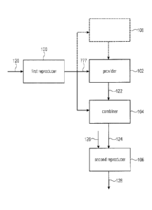
One embodiment of an inventive apparatus for reproducing an audio signal and,
thereby
extending the bandwidth thereof, is shown in Fig. I a. The apparatus comprises
a first
reproducer 100, a provider 102, a combiner 104 and a second reproducer 106.
Optionally, a
transition detector 108 may be provided. The first reproducer 100 receives at
an input
thereof first data 120 representing a coded version of a first portion of
audio data in a first
frequency band. For example, the first data 120 may correspond to audio signal
portion
705 shown in Fig. 4b. The first reproducer 100 reproduces the audio signal in
the first
frequency band based on the first data 120. For example, the first reproducer
100 may be
formed by the audio decoder 714 shown in Fig. 4b. The first reproducer 110
outputs the
audio signal in the first frequency band, which may correspond to audio signal
777 shown
in Fig. 4b. Audio signal 777 is applied to provider 102, which provides for a
patch signal
122 in the second frequency band. The patch signal 122 is at least partially
uncorrelated
CA 02882775 2015-02-23
12
WO 2014/033131 PCT/EP2013/067730
with respect to the first portion of the audio signal 777 or is at least
partially a decorrelated
version of the first portion of the audio signal, which has been shifted to
the second
frequency band. The audio signal 777 and the patch signal 122 are combined,
such as
added, in combiner 104. The combined signal 124 is output and applied to the
second
reproducer 106. The second reproducer 106 receives the combined signal 124 and
second
data 126 representing side information on a second portion of the audio signal
in a second
frequency band. For example, the second data 126 may correspond to decoded
parameters
713 described above with respect to Fig. 4b. The second reproducer 106
reproduces the
audio signal in the second frequency band based on the patch signal (within
the combined
signal 124) and based on the second data 126.
In embodiments of the invention, the first frequency band may correspond to
the frequency
range associated with the first portion of the audio signal shown in Fig. 7a,
and the second
frequency band may correspond to the frequency range associated with the
second portion
of the audio signal shown in Fig. 7a.
According to the embodiment shown in Fig. la, the second reproducer 106
outputs a
reproduced audio signal 128 with a high bandwidth.
In the alternative embodiment shown in Fig. lb, the output of provider 102 is
coupled to
the second reproducer 106 and the output of second reproducer 106 is coupled
to combiner
104. Thus, according to the embodiment shown in Fig. lb, an audio signal 130
in the
second frequency band is reproduced from the patch signal provided by provider
102 prior
to combining the patch signal with the first portion 777 of the audio signal.
Again, the
second reproducer reproduces the audio signal 130 in the second frequency band
based on
the second data 126 and the patch signal 122. According to the embodiment
shown in Fig.
lb, the combiner 104 outputs the reproduced audio signal 128.
In embodiments of the invention, the provider comprises a shifting unit and a
decorrelator,
which are configured to generate the patch signal as a decorrelated version of
the first
portion of the audio signal shifted to the second frequency band. In
embodiments of the
invention, the provider is configured to provide a synthetic patch signal
which is
uncorrelated with respect to the first portion of the audio signal. In
embodiments of the
invention, the provider is configured to provide a plurality of patch signals
for a plurality
of higher frequency bands. In such embodiments the second reproducer and the
second
combiner are adapted to reproduce a plurality of second signal portions and to
combine the
plurality of signal portions into the reproduced audio signal.
CA 02882775 2015-02-23
13
WO 2014/033131 PCT/EP2013/067730
An embodiment of an apparatus for reproducing an audio signal using bandwidth
extension, which uses decorrelated sub-band audio signals, is shown in Fig. 2.
The
apparatus receives a baseband signal from the core codec, which may be signal
777 shown
in Fig. 4b. Signal 777 is applied to a shifting unit 200. Shifting unit 200 is
configured to
shift signal 777 from the low-frequency range to a high-frequency range, such
as from a
frequency range associated with the low-frequency portion 4 in Fig. 7a to the
frequency
range associated with the high-frequency portion 6 in Fig. 7a.
Shifting unit 200 may be configured to simply copy-up signal portion 777 to
the high-
frequency range in the frequency domain. Alternatively, shifting unit 200 may
be
implemented as a single sideband modulation unit configured to perform a
single sideband
modulation in the time domain in order to shift the first portion of the audio
signal from the
first frequency band to the second frequency band.
The shifted first portion of the audio signal is applied to a decorrelation
unit 202a. The
shifted decorrelated first portion of the audio signal is output by the
decorrelation unit 202a
as a patch signal 204. The patch signal 204 is applied to a patching unit 206,
in which the
patch signal 204 is combined with the first portion 777 of the audio signal.
For example,
the patch signal and the first portion of the audio signal are concatenated or
added in
patching unit 206. The combined signal is output from patching unit 206 and
applied to a
post-processing unit 210.
Post-processing unit 210 receives second data 212 and represents a second
reproducer
configured to reproduce the second portion of the audio signal in a second
frequency band
based on the second data 212 and the patch signal 204 (which is included in
the combined
signal 208). Again, the second data 212 represent side infoiniation and may
correspond to
decoded parameters 713 explained above with respect to Fig. 4b. A fullband
output 214 of
post-processing unit 210 represents the reproduced audio signal.
In the embodiment shown in Fig. 2, shifting unit 200 and decorrelation unit
202a represent
a provider configured to provide a patch signal 204.
In embodiments of the invention, shifting unit 200 may be configured to shift
the first
portion 777 of the audio signal into a plurality of p different frequency
bands. A
decorrelation unit 202a-202p may be provided for each shifted version in order
to provide
for p patch signals. In case more than one patch is used, (such as p patches),
the p patches
should be uncorrelated among each other and the LF band. Then, the shifted
versions
associated with each frequency band are combined within patching unit 206.
Second data
14
CA 02882775 2015-02-23
WO 2014/033131 PCT/EP2013/067730
representing side information for each of the higher frequency bands may be
provided to
the post-processing unit 210 so that a plurality of higher frequency portions
of the audio
signal are reproduced in post-processing unit 210.
In embodiments of the invention, the first and second frequency bands (and the
optionally
further frequency bands) may overlap or may not overlap in the frequency
direction.
Accordingly, in embodiments of the invention, the provider comprises a shifter
unit
configured to shift a first portion of an audio signal in a first frequency
band to a second
frequency band or to a plurality of different second frequency bands, and a
decorrelator for
decorrelating the shifted version of the first portion of the audio signal
from the first
portion of the audio signal. In embodiments of the invention, the decorrelator
may have the
same properties as known for example from spatial audio coding decorrelation.
In the
embodiments of the invention, the decorrelator may provide a sufficient
decorrelation in
order to avoid the signal distortions and artifacts which are typical for
conventional
bandwidth extensions using spectral band replication. The decorrelator may
provide for a
preservation of the spectral envelope of the first portion of the audio signal
and/or may
provide for a preservation of the temporal envelope, i.e. the transients, of
the first portion
of the audio signal. Designing an appropriate decorrelator thus might
typically involve a
trade-off to be made between transient preservation and decorrelation.
In embodiments of the invention, the decorrelator may be implemented as an IIR
(IIR=
infinite impulse response) filter in time domain or sub-band time domain, e.g.
an all-pass
filter, in which decorrelation is achieved via group-delay variations. In
embodiments of the
invention, the decorrelator may be configured to provide for phase
randomization of
spectral coefficients in a complex (oversampled) transform/filterbank
representation (DFT,
QMF representation) (DFT = discrete Fourier Transform; QMF = quadrature mirror
filter).
In embodiments of the invention, the decorrelator may be configured in order
to provide
for an application of a frequency-dependent time delay in a filterbank
representation.
Embodiments of the invention may comprise a signal adaptive decorrelator that
varies the
degree of decorrelation in order to preserve transients. A high decorrelation
may be
provided for quasi-stationary signals, and a low decorrelation may be provided
for
transient signals. Accordingly, in embodiments of the invention, the provider
for providing
the patch signal may be switchable between different degrees of decorrelation.
In embodiments, the provider for providing the patch signal may be switchable
between
different degrees of decorrelation depending on whether the first signal
portion comprises
15
CA 02882775 2015-02-23
WO 2014/033131 PCT/EP2013/067730
an indicator for a strong correlation between the first portion of the audio
signal and the
second portion of audio signal. Embodiments for such an indicator are a
transient in the
first portion of the audio signal, voiced speech consisting of pulse trains in
the first portion
of the audio signal and/or the sound of brass instruments in the first portion
of the audio
signal. In the following, embodiments are described, in which the indicator is
a transient in
the first portion of the audio signal.
In embodiments of the invention, the apparatus may comprise a detector
configured to
detect whether the first portion of the audio signal comprises a transient.
Such a detector
108 is schematically shown in Figs. la and lb. Depending on the output signal
of detector
108, provider 102 may be configured to provide the patch signal with a high
decorrelation
for quasi-stationary signals, i.e. when the first portion of the audio signal
does not have a
transient), and a low decorrelation if the first portion of the audio signal
has transient
signals.
In alternative embodiments of the invention, the apparatus may comprise a
signal adaptive
decorrelator that is activated for quasi-stationary signals and deactivated
for transient
signal portions. In other words, the provider may be configured to output the
shifted first
signal portion without decorrelation thereof in case the first signal portion
comprises
transient signal portions and to output the decorrelated patch signal only in
case the first
signal portion does not comprise transients or transient signal portions. In
such
embodiments, the second reproducer is configured to reproduce the audio signal
in the
second frequency band based on the second data and the patch signal if the
first portion of
the audio signal does not comprise a transient and is configured to reproduce
the audio
signal in a second frequency band based on the second data and a version of
the first
portion of the audio signal, which has been shifted to the second frequency
band and which
has not been decorrelated, if the first portion of the audio signal comprises
a transient.
A transient or transient portions may be regarded as consisting in the fact
that the audio
signal changes a lot in total, i.e. that e.g. the energy of the audio signal
changes by more
than 50% from one temporal portion to the next temporal portion, i.e.
increases or
decreases. The 50% threshold is only an example, however, and it may also be
smaller or
greater values. Alternatively, for a transient detection, the change of energy
distribution
may also be considered, e.g. in the transition from a vocal to a sibilant.
In embodiments of the invention, the provider may be configured to provide a
synthetic
patch signal which is uncorrelated with respect to the first portion of the
audio signal. In
other words, patching with an uncorrelated synthetic patch signal (such as
synthetic noise)
CA 02882775 2015-02-23
16
WO 2014/033131 PCT/EP2013/067730
might already be sufficient if parametric post-processing is fine granular
(high bit-rate
codec scenario) or if the signal's HF band is noisy-like anyway.
In embodiments of the invention, a correlation of the LF band and the HF band
within a
bandwidth extension (like SBR) is nevertheless helpful for enhancing a too
coarse time
grid of parametric post-processing (e.g. due to a low bit-rate codec
scenario), an accurate
reproduction of transients, and a preservation of tones that have a rich
overtone structure
(usually, tonality is not affected by decorrelation and thus the preservation
of tonality does
not pose a problem in designing a decorrelator).
As far as decorrelators known e.g. from spatial audio coding decorrelation are
concerned,
reference is made to WO 2007/118583 Al, for example.
In embodiments of the invention, provider 102 may comprise an adaptive
decorrelator,
which adjusts decorrelation of the HF patches based on a parameter transmitted
from an
encoder to the decoder. In such embodiments, the apparatus is configured for
reproducing
an audio signal based on the first data, the second data and third data
comprising
information on a degree of decorrelation to be used between the first portion
of the audio
signal and a patch signal based on which the second portion is reproduced when
reproducing the audio signal from the coded audio signal. Such third data may
be added to
coded audio data on the encoder side, such as by a decorrelation information
adder 300
shown in Fig. 3 of the present application. The apparatus shown in Fig. 3
corresponds to
the apparatus shown in Fig. 4a except for the decorrelation information adder.
The decorrelation information adder 300 receives the output of low-pass filter
702 and may
detect properties from the output signal of low-pass filter 702. For example,
decorrelation
information adder may detect transients in the output signal of the low-pass
filter 702.
Depending on the properties of the output of low-pass filter 702,
decorrelation information
adder adds to the coded audio signal 710 information on a degree of
decorrelation to be
used between the first portion of the audio signal and a patch signal based on
which the
second portion is reproduced when reproducing the audio signal from the coded
audio
signal. For example, the decorrelation information may instruct the provider
at the
decoder-side to perform a low decorrelation or not any decorrelation at all in
case there are
transient portions in the low-frequency portion of the audio signal.
In embodiments of the invention, the decorrelation information adder may also
receive the
high-frequency portion 706 of the audio signal and may be configured to derive
properties
therefrom. For example, in case the decorrelation information adder detects
that the HF
CA 02882775 2015-02-23
17
WO 2014/033131 PCT/EP2013/067730
band is noise-like, it may advise the provider on the decoder-side to provide
the patch
signal based on a synthetic noise signal.
In such embodiments, the coded audio signal 320 represented by data stream 710
comprises first data 321 representing a coded version of a first portion of an
audio signal,
second data 322 representing side information on a second portion of the audio
signal in a
second frequency band, and information 323 on a degree of decorrelation to be
used
between the first portion of the audio signal and a patch signal based on
which the second
portion is reproduced when reproducing the audio signal from the coded audio
signal.
Accordingly, embodiments of the invention provide for an improved approach for
reproducing an audio signal, i.e. for a decoder-side extension of the audio
signal
bandwidth. In other embodiments, the invention provides for an apparatus for
generating a
coded audio signal. In even other embodiments, the invention relates to such
coded audio
signals.
The advantageous effect achieved by the inventive approach can be made visible
by a
comparison of the autocorrelation sequence of the noise signal envelope for
copy-up SBR
(shown in Fig. 5a) with the autocorrelation sequence of the noise signal
envelope of
decorrelated patches as shown in Fig. 5b of the present application. Fig. 5b
is the
autocorrelation function of the magnitude envelope of white noise, wherein the
bandwidth
is extended with three patches uncorrelated among each other and to the LF
band. Fig. 5b
clearly shows the disappearance of the unwanted side maxima shown in Fig. 5a.
The present application is applicable or suitable for all audio applications
in which the full
bandwidth is not available. The inventive approach may find use in the
distribution or
broadcasting of audio content such as, for example with digital radio,
internet streaming
and audio communication applications. Embodiments of the invention are related
to a
bandwidth extension using decorrelated sub-band audio signals.
Although some aspects have been described in the context of an apparatus, it
is clear that
these aspects also represent a description of the corresponding method, where
a block or
device corresponds to a method step or a feature of a method step.
Analogously, aspects
described in the context of a method step also represent a description of a
corresponding
block or item or feature of a corresponding apparatus.
Depending on certain implementation requirements, embodiments of the invention
can be
implemented in hardware or in software. The implementation can be performed
using a
18
CA 02882775 2015-02-23
WO 2014/033131 PCT/EP2013/067730
digital storage medium, for example a floppy disk, a DVD, a CD, a ROM, a PROM,
an
EPROM, an EEPROM or a FLASH memory, having electronically readable control
signals stored thereon, which cooperate (or are capable of cooperating) with a
programmable computer system such that the respective method is performed.
Some embodiments according to the invention comprise a data carrier having
electronically readable control signals, which are capable of cooperating with
a
programmable computer system, such that one of the methods described herein is
performed.
Generally, embodiments of the present invention can be implemented as a
computer
program product with a program code, the program code being operative for
performing
one of the methods when the computer program product runs on a computer. The
program
code may for example be stored on a tangible machine readable carrier.
Other embodiments comprise the computer program for performing one of the
methods
described herein, stored on a machine readable carrier or a non-transitory
storage medium.
In other words, an embodiment of the inventive method is, therefore, a
computer program
having a program code for performing one of the methods described herein, when
the
computer program runs on a computer.
A further embodiment of the inventive methods is, therefore, a data carrier
(or a digital
storage medium, or a computer-readable medium) comprising, recorded thereon,
the
computer program for performing one of the methods described herein.
A further embodiment of the inventive method is, therefore, a data stream or a
sequence of
signals representing the computer program for performing one of the methods
described
herein. The data stream or the sequence of signals may for example be
configured to be
transferred via a data communication connection, for example via the Internet.
A further embodiment comprises a processing means, for example a computer, or
a
programmable logic device, configured to or adapted to perform one of the
methods
described herein.
A further embodiment comprises a computer having installed thereon the
computer
program for performing one of the methods described herein.
CA 02882775 2015-02-23
19
WO 2014/033131 PCT/EP2013/067730
In some embodiments, a programmable logic device (for example a field
programmable
gate array) may be used to perform some or all of the functionalities of the
methods
described herein. In some embodiments, a field programmable gate array may
cooperate
with a microprocessor in order to perfotin one of the methods described
herein. Generally,
the methods are preferably performed by any hardware apparatus.
The above described embodiments are merely illustrative for the principles of
the present
invention. It is understood that modifications and variations of the
arrangements and the
details described herein will be apparent to others skilled in the art. It is
the intent,
therefore, to be limited only by the scope of the impending patent claims and
not by the
specific details presented by way of description and explanation of the
embodiments
herein.