Note: Descriptions are shown in the official language in which they were submitted.
CA 02883482 2015-02-27
WO 2014/033465
PCT/GB2013/052279
Long Wavelength Infrared Detection and Imaging with Long Wavelength Infrared
Source
FIELD OF INVENTION
The present invention relates to a method and apparatus for long wavelength
infrared
detection and, in preferred embodiments, hyperspectral detection and
hyperspectral
imaging. It also relates to an optical parametric device useful in this
context. The
present invention is particularly relevant to real time standoff detection,
and in
particular detection of volatile substances in real world environments.
BACKGROUND OF INVENTION
There are a number of practical applications for remote detection and, if
possible,
imaging of gaseous species present in a low concentration. These include
remote
detection of leaks of inflammable or poisonous materials and remote detection
of
explosives. At present, it is difficult to detect and particularly to image
materials
remotely in sufficiently low concentrations, because the available techniques
are not
sufficiently powerful to detect materials in low concentrations reliably or
sufficiently
able to discriminate relevant species.
One particularly promising technique is back-scatter absorption gas imaging
(BAG!).
This technique involves providing a source of light tuned to a wavelength
where the
target species has an absorption band, and a detector for detecting light
scattered
from a target area. The presence of gas will occlude an image of a scene from
the
target area captured where there is no gas absorption (for example, at another
wavelength where there is no absorption from the target species).
It is desirable for the linewidth of the light source to be equal to or less
than the width
of the absorption band. For short chain hydrocarbon molecules, absorption
bands of
interest lie in the 2-4 micron range. For these parameter constraints, a
particularly
suitable light source is an optical parametric oscillator (OPO) using a
nonlinear
crystal such as periodically poled lithium niobate (PPLN). An OPO is a complex
optical source which comprises a pump laser and a nonlinear crystal. The
nonlinear
crystal converts the pump light into two lower frequency (and hence longer
wavelength) waves by virtue of a second order nonlinear optical interaction.
The
sum of the frequency of these two output waves is equal to the frequency of
the
pump input. The lower frequency (and longer wavelength) output is termed the
idler,
and the higher frequency (and shorter wavelength) output is termed the signal.
1
CA 02883482 2015-02-27
WO 2014/033465
PCT/GB2013/052279
The use of BAGI techniques using OPO light sources has been extensively
studied
at Sandia National Laboratories (SNL). Representative papers from this
research
group include "Backscatter Absorption Gas Imaging ¨ a New Technique for Gas
Visualization" by T.G. McRae and T.J. Kulp, Applied Optics, 1993, 32(21)
pp.4037-
4050; "Active infrared imagers visualize gas leaks" by T.J. Kulp and T. McRae,
Laser
Focus World, 1996, 32(6) p.211; and "Demonstration of differential backscatter
absorption gas imaging" by P.E. Powers et al, Applied Optics, 200, 39(9),
pp.1440-
48. Systems using both continuous wave and pulsed OPOs are described, and
imaging systems are described including focal-plane array cameras and
rastering
scanners. However, these systems are generally expensive and immobile, and not
well adapted to real world applications outside a laboratory environment.
A development on this approach is described in WO 2006/061567 Al. This
discloses
a BAGI system using an OPO in which the pump wave laser source and the
nonlinear medium are provided in the same optical cavity. This approach allows
for
more efficient use of pump laser power, and in combination with use of Q-
switching,
allows for use in a rapidly pulsed mode which can be used effectively with
raster
scanning to construct an image of a scene. This makes it possible to produce a
less
expensive and more mobile device capable of IR imaging using BAGI techniques.
While these techniques are effective to image the presence or absence of
classes of
material, such as short chain hydrocarbons, they lack the resolution to allow
specific
materials of interest to be distinguished from a more general class. This is
because
use of OPOs of this type only allows access to the medium wavelength infrared
(MWIR) region, typically defined as extending from 3-8 pm and shorter
wavelengths
¨ for example, the working range of a PPLN OPO is typically from 2-4 pm. This
MWIR region contains absorption bands which are effective to allow a specific
class
of material (such a ketone, an unsaturated hydrocarbon or a saturated
hydrocarbon)
to be recognised, but not to allow one material within that class to be
distinguished
from another.
Recognition of individual molecular species typically requires a
spectrum over a broader spectral region. Multiple spectral bands, including
bands in
the long wavelength infrared (LWIR), typically defined as extending from 8-15
pm,
can then be used and matched with known or calculated spectra to determine the
presence or absence of a particular species. The "fingerprint region" for
infrared
spectroscopy lies largely in the LWIR ¨ the fingerprint region is normally
taken as
extending between 500 and 1500 cm-1, or 6.67-20 pm. Spectral lines in the
2
CA 02883482 2015-02-27
WO 2014/033465
PCT/GB2013/052279
fingerprint region generally include relatively sharp lines which result from
bending
vibrations specific to the geometry of an individual molecule ¨ these spectral
lines
distinguish different members of a class from each other and can thus be used
to
identify individual molecular species. Existing BAGI techniques cannot however
work
effectively in most of the signature region, as known technologies do not
function
effectively beyond the MWIR region.
SUMMARY OF INVENTION
Accordingly, in a first aspect the invention provides an infrared detection
system,
comprising: a laser source providing radiation for illuminating a target,
wherein the
radiation is tuned to at least one wavelength in the fingerprint region of the
infrared
spectrum; a detector configured to detect radiation backscattered from the
target;
and an analyser adapted to match detected radiation signals against
predetermined
spectra to determine from at least the presence or absence of detected signal
in said
at least one wavelength whether a predetermined volatile compound is present.
This arrangement allows for effective identification of the presence or
absence of
specific volatile compounds in remote detection.
Advantageously, the laser source comprises an optical parametric oscillator
having a
pump laser and a nonlinear medium. Preferably, the nonlinear medium comprises
a
ZnGeP2 (ZGP) crystal. This laser source provides good access to the
fingerprint
region. In one preferred arrangement, the nonlinear crystal is disposed inside
a
cavity of the pump laser.
In a preferred arrangement, both an idler beam and a signal beam of the
optical
parametric laser are provided as output radiation. Preferably. the idler beam
provides output radiation at least partly within the fingerprint region and
the signal
beam provides output radiation at least partly at shorter wavelengths than in
the
fingerprint region. This is achievable using a ZGP crystal as nonlinear
medium.
Preferably the system further comprises tuning means to tune the laser source
between a plurality of wavelengths, wherein the infrared detection system is a
hyperspectral detection system. The analyser may then be adapted to determine
from the presence or absence of detected signal in more than one wavelength of
the
plurality of wavelengths whether a predetermined volatile compound is present.
3
CA 02883482 2015-02-27
WO 2014/033465
PCT/GB2013/052279
Moreover, the analyser may be adapted to determine from the presence or
absence
of detected signal in wavelengths of the plurality of wavelengths whether one
or more
of a plurality of predetermined volatile compounds are present.
In some embodiments a plurality of laser sources are provided, comprising at
two
optical parametric oscillators with different nonlinear crystals.
Preferably, the one or more laser sources provide pulsed output radiation.
In a preferred arrangement, the detector comprises an imaging system and the
infrared detection system comprises an imager, preferably one that provides an
image in real time.
An imaging system is particularly effective in combination with pulsed output
radiation
from the laser sources. The infrared detection system may then comprise a
scanning
system for scanning a target region wherein the scanning system is
synchronised
with the pulsed output radiation. A pulse of radiation output by the one or
more laser
sources at a wavelength may then determine an image pixel value at that
wavelength. This enables effective hyperspectral imaging.
Preferably, the analyser matches detected radiation signals against
predetermined
spectra to determine the presence or absence of the predetermined material.
Where
the detection system is hyperspectral, the analyser may match detected
radiation
signals against predetermined spectra at a plurality of wavelengths determined
for
that predetermined material. At least some of the plurality of wavelengths may
lie in
the fingerprint region. Where the detection system is an imaging system, the
analyser may determine a portion of an image where a predetermined material is
present or absent. The presence or absence of a predetermined material could
then
be represented in a false colour image.
In a second aspect, the invention provides a method of determining the
presence or
absence of a predetermined volatile compound comprising: illuminating a target
with
radiation from a laser source tuned to at least one wavelength in the
fingerprint
region of the infrared spectrum; detecting radiation backscattered from the
target;
and determining by matching detected radiation signals against predetermined
spectra from at least the presence or absence of detected signal in said at
least one
wavelength whether a predetermined volatile compound is present.
4
CA 02883482 2015-02-27
WO 2014/033465
PCT/GB2013/052279
According to a third aspect of the present invention there is provided an
optical
parametric device having a laser gain medium for generating a pump beam in a
pump laser cavity, a pump laser source and a nonlinear medium comprising a
ZnGeP2 (ZGP) crystal, wherein on stimulation by the pump beam, the ZnGeP2
(ZGP) crystal is adapted to generate a signal beam having a wavelength in a
fingerprint region of the spectrum and an idler beam having a wavelength in
the mid-
infrared region of the spectrum, and wherein the laser gain medium and the
ZnGeP2
(ZGP) crystal are located in the pump laser cavity.
Preferably, the pump laser source comprises a Ho:YAG laser.
Using this approach, an intra-cavity optical parametric oscillator may be
formed using
two beam splitter mirrors to separate the signal and idler beams from the pump
beam. The beam splitter mirrors may comprise ZnSe mirrors.
Preferably, the pump beam is pulsed. In particular, the pump laser may be Q-
switched, for example comprising an acousto-optic Q-switch.
In preferred embodiments, the optical parametric device is adapted for tuning
the
signal beam and the idler beam over a range of wavelengths. In one arrangement
to
achieve this, it may further comprise a rotatable motion stage, wherein the
ZnGeP2
(ZGP) crystal is mounted on the rotatable motion stage and the signal and
idler
beams are tuned by rotation of the rotatable motion stage.
Features described above in respect of the first and second aspects of the
invention
may also apply to this third aspect.
BRIEF DESCRIPTION OF DRAWINGS
Specific embodiments of the invention will be described below, by way of
example,
with reference to the accompanying drawings, of which:
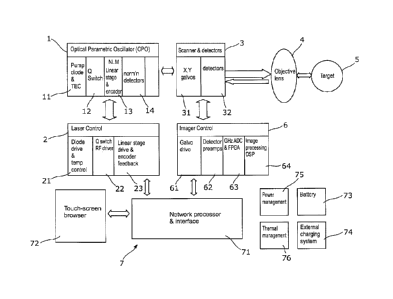
Figure 1 shows the elements of a hyperspectral imaging system in accordance
with
an embodiment of the invention;
Figure 2 shows a LWIR laser source section for use in embodiments of the
invention;
Figure 3 shows a scanning system for use in embodiments of the invention;
5
CA 02883482 2015-02-27
WO 2014/033465
PCT/GB2013/052279
Figure 4 shows schematically a detection system for use in embodiments of the
invention;
Figure 5 illustrates schematically a process for recognising presence or
absence of a
predetermined volatile compound; and
Figure 6 illustrates imaging of a predetermined material using processes
described in
this specification to illustrate the results of using hyperspectral imaging
for detection.
The main elements of a hyperspectral detection system ¨ in this case, a
hyperspectral imaging system, but the imaging aspect can be removed to leave a
detection system ¨ are set out in Figure 1.
A laser source section 1 comprises one or more laser sources for providing
radiation
tunable between at least a plurality of wavelengths for illuminating a target.
As will
be discussed below, the laser source or sources extend into the LWIR region to
allow
for use of the fingerprint region of the infrared section. The laser source
section 1
comprises in this embodiment one or more optical parametric oscillators
(0P0s),
though embodiments may employ other types of optical source tunable in
relevant
spectral regions. In a preferred arrangement there is a single OPO used for
both
LWIR and MWIR operation ¨ in alternative arrangements there may be one OPO for
MWIR operation and another OPO for LWIR operation. Each OPO in this
embodiment requires a pump laser 11, a Q switch 12 (to enable high speed
pulsed
operation), a non-linear assembly 13 (as described in more detail below, but
comprising a non-linear crystal and a means for moving it with respect to the
pump
beam to achieve tuning) and detectors 14 to measure outputs for use in
calibration
and control. A laser source control section 2 comprises a drive and
temperature
control circuit 21 for the pump laser 11, an RF driver 22 for the Q switch 12,
and a
stage drive and feedback system 23 for the non-linear assembly 13.
The light output by the laser source section 1 reaches the scanning part 31 of
the
scanning and detection assembly 3. The scanning part 31 comprises in this
embodiment X and Y galvos to produce a raster scan of a target region. The
rasterised output light passes through an objective lens 4 to reach the target
region
5. Unabsorbed light is backscattered from the target region 5 and received
through
the objective lens 4 at detectors 32.
The scanning and detection assembly 3 is controlled by an imager controlling
system
6. This comprises the following: a galvo drive system 61 to drive the scanning
part
6
CA 02883482 2015-02-27
WO 2014/033465
PCT/GB2013/052279
31; detector preamplifiers 62 to preamplify the signals received at the
detectors 32
for subsequent signal processing; a signal conversion system 63 comprising an
analogue to digital converter (ADC) operating at suitable speeds (GHz speeds
for
real time hyperspectral imaging) and a field programmable gate array (FPGA) to
prepare signals for analysis, including providing appropriate gating so that
detected
signals are associated correctly with a particular position in a raster scan;
and a
digital signal processor (DSP) 64 programmed to produce hyperspectral images
from
the converted and gated signals. The image processing system as a whole may
provide further analysis of the hyperspectral images produced by the DSP 64,
the
image processing system as a whole providing analysis to determine from at
least
the presence or absence of detected signal in one or more wavelengths within
the
fingerprint region whether a predetermined volatile compound is present.
The system as a whole contains further interface and control elements 7. The
laser
source control section 2 and the imager controlling system 6 are connected to
a
network processor and interface 71 ¨ this allows for user interaction with the
system
through a user interface 72. The system as a whole has additional systems
allowing
it to operate effectively as a standalone instrument ¨ battery 73, external
charging
system 74, power management system 75 and thermal management system 76.
Individual sections and subsystems of this embodiment will now be described in
more detail. Some features of this embodiment are described in greater detail
in WO
2006/061567 Al, to which the reader is directed. Some features of this
embodiment
are also found in the Firefly-IR-SC device provided commercially by M Squared
Lasers Limited ¨ this device, embodying aspects of the technology described in
WO
2006/061567 Al, comprises a pulsed MWIR laser system with a scanning accessory
for imaging.
Figure 2 shows a LWIR laser source section 200 for use in embodiments of the
invention. This comprises an intra-cavity OPO with Q-switching, as used in the
Firefly-IR-SC device. There are however several differences in the arrangement
provided here, most particularly the use of a different non-linear medium, ZGP
(ZnGeP2).
The non-linear material ZGP is useful for generating tunable light in the
fingerprint
region of the optical spectrum (6 to 10 microns). This region contains strong
absorption features for many chemical groups. As is described below, by using
ZGP
7
CA 02883482 2015-02-27
WO 2014/033465
PCT/GB2013/052279
it is also possible, from the same device, to generate light in the important
2.5 to 3.5
micron mid-infrared region which contains key absorption in hydrocarbons.
Prior art
approaches to use of ZGP in an optical parametric oscillator involved pumping
at 2
microns using pump lasers such as Ho:YAG. The oscillation threshold of the
resulting OPO is high and large pump lasers are required to make the OPO work.
In embodiments described below, reduction of the pump power required for an
OPO
is achieved by placing the OPO inside the pump laser cavity. This is found to
increase dramatically the intra-cavity optical field, making it possible for
the OPO to
operate at lower pump powers.
An effective approach to achieving high intra-cavity optical fields is to keep
optical
losses on mirrors and in transmission of optical components within the cavity
very
low. ZGP has a large absorption loss at 2 microns where the Ho:YAG laser
operates.
This appears to suggest that placing the ZGP OPO intra-cavity within the
Ho:YAG
laser will not be advantageous.
In reality the Ho:YAG has a large gain and, so the system is able to support
large
intra-cavity losses. Even field enhancements of a factor of 2 or 3 make a
significant
difference in the size and practicality of the pump laser required ¨ this can
lead to
reduction of pump laser power from 20W to 8W, makes the choice of components
very much easier and reducing the overall cost of the device while increasing
flexibility of design.
A further benefit of intra-cavity location is that the pump beam passes
through the
OPO in both directions without the need for optical isolation between the pump
laser
and OPO. This makes the devices more compact, cheaper and lowers the threshold
further.
The individual elements of the system shown in Figure 2 are discussed below.
The pump laser in this embodiment is a Ho:YAG laser 201, lasing at 2090 nm ¨
this
laser type is extensively used for MWIR OPOs. In this case, to provide enough
power to reach the oscillation threshold for long wavelength operation, an
intracavity
design is used with the nonlinear crystal located within the laser cavity of
the
holmium-doped yttrium aluminium garnet (Ho:YAG) laser 201. The Ho:YAG laser
201 is pumped with a commercially available (for example from IPG Photonics
Limited) thulium fiber laser operating at 1908 nm ¨ in the arrangement shown,
the
8
CA 02883482 2015-02-27
WO 2014/033465
PCT/GB2013/052279
1908 nm fiber output is first reduced by a 3:1 telescope 202. Alternative
diode lasers
could be used to reduce the overall size of the system. The Ho:YAG laser 201
is Q-
switched using an acousto-optic Q-switch 203 (for example, Gooch and Housego
QS041-10M-H17). Both the Ho:YAG crystal and the Q-switch are water cooled. A
switching rate of 20kHz is used in this exemplary embodiment.
The intra-cavity OPO is formed using two ZnSe beam splitter mirrors 204 to
separate
the OPO beam from the 2090 nm pump beam and two curved end mirrors 205, with
a radius of curvature 150 mm each. The spot diameter in the ZGP crystal 206
was
optimized by moving the cavity mirrors to achieve a match to the pump spot
size.
Dielectric filters were used to ensure that no residual pump light at 2090 nm
was
detected. The beam splitters 204 are coated for high reflectivity at 2.8-3.3
pm and
high transmission at 5-9 pm. The end mirror 205 at the output is highly
reflecting at
2090 nm and highly transmitting 5-9 pm.
While an intra-cavity approach is shown here, an external cavity can also be
used in
embodiments of the invention. In the external cavity case, larger pump powers
are
required to reach threshold for the OPO, but once achieved, large output
powers can
be expected. In the internal cavity case, as indicated above, the threshold
for OPO
operation is much lower and can be achieved with more modest pumps. A low
output power will often be sufficient for spectroscopic applications. As
stated above,
a further advantage to the intra-cavity scheme is that the pump beam is double
passed through the ZGP crystal. The double pass of the pump ensures that there
is
signal gain in both directions. The combination of the pump enhancement and
the
double pass gain lowers the OPO oscillation threshold further.
Other choices of nonlinear crystal are possible in this range of operation ¨
one
suitable material is orientation-patterned gallium arsenide (OP GaAs), others
are
silver gallium selenide (AgGaSe2), gallium selenide (GaSe) and silver gallium
sulphide (AgGaS2). This embodiment is also arranged as a high repetition rate
pulsed system by inclusion of Q-switch 203 ¨ as the person skilled in the art
will
appreciate, continuous wave or less rapidly pulsed systems can be provided
using
other component choices.
As is described above, an OPO produces a longer wavelength idler beam and a
shorter wavelength signal beam. Either or both of the idler and the signal
beam can
be used for spectroscopic purposes. The advantage of using both beams is that
this
9
CA 02883482 2015-02-27
WO 2014/033465
PCT/GB2013/052279
can extend the spectral range over which a single OPO can be used ¨ in the
case of
ZGP, this allows the use of the idler beam for essentially an LWIR region of
operation
(in the fingerprint region), with the signal beam providing coverage in the
MWIR
region. This is a significant advantage of this approach ¨ using ZGP as the
nonlinear
crystal, radiation can be generated in both the 3-4 micron range and the 5-9
micron
range with one system if both idler beam and signal beam are used. An
alternative
approach is to use multiple laser source sections with different nonlinear
materials to
cover different ranges ¨ these could then be optimised to provide either the
signal
beam or the idler beam as output, if preferred. A suitable MWIR system would
be
that described in WO 2006/061567 Al, which uses periodically poled lithium
niobate
(PPLN) as a nonlinear medium.
A motion stage 207 is provided to move the nonlinear crystal 206 in order to
tune the
OPO to different output wavelengths. In the case of ZGP, the approach taken is
to
rotate the nonlinear crystal to tune it to a different wavelength. Phase
matching is
achieved in the nonlinear material, which is strongly birefringent, by using
the
different polarization states available ¨ a tuning curve determining signal
and idler
wavelengths for given pump wavelengths is established for rotational angle of
the
nonlinear crystal. In the case of ZGP, 15 degrees of rotation of the crystal
can tune
the idler from 5 to 9 microns while tuning the signal between 2.7 and 3.8
microns.
Motion stage 207 is in this case a rotation stage to which the nonlinear
crystal 206 is
bonded ¨ conventional commercially available rotation stages provide
sufficient
accuracy for this purpose.
In the case of a periodically poled material (like PPLN), the motion stage 207
can be
a translation stage, as the tuning is instead achieved by the poling
separation, which
is varied orthogonally to the direction of travel of light through the
material, so
translation of the nonlinear crystal 206 in this orthogonal direction can be
used for
tuning..
For effective detection of the presence or absence of an absorption in the
target
molecule, it is desirable for the linewidth of the output beam incident upon
the target
to be similar to or narrower than the linewidth of the spectral line resulting
from that
absorption. The system described provides generally suitable linewidths for
the
spectroscopy of hydrocarbons in the fingerprint region, but if narrower
linewidths are
required, the laser source section 200 may also be provided with an etalon.
CA 02883482 2015-02-27
WO 2014/033465
PCT/GB2013/052279
An exemplary scanning system is shown in Figure 3. The purpose of the scanning
system is to scan the incident beam (whether signal, idler or both) across the
target
region in order to produce a rasterized scan, and so construct an image of the
target
region. The same optics are used to transmit the incident beam and to capture
the
backscattered beam for transmission to the detector system.
In the arrangement shown in Figure 3, a collimating lens LC with high
transmission in
the relevant spectral region (e.g. calcium fluoride) collects the output beam
from the
OPO and this is directed by mirror m on to a first scanning mirror (in this
case,
polygonal scanner PS). Light from the first scanning mirror is reflected on to
the
second scanning mirror, tilting mirror TM. These two scanning mirrors provide
two
axes of the rasterised scan ¨ polygonal scanner PS provides slower scanning
along
one (X) axis, whereas the tilting mirror TM driven by high speed galvanometer
G
provides the rapid scan along the Y axis for each X axis position.
Scanning is synchronised with the pulsed operation of the laser system. Use of
Q-
switching provides a rapidly pulsed pump laser, and so OPO output. Each pulse
is
sampled to provide a triggering signal, and the triggering signal is used to
define a
pixel. The scanning mirrors are synchronized with the pulsed operation of the
laser
so that the backscattered light received in the detection system can be
interpreted as
pixel data and hence as image data. The imaging system is also synchronized
with
translation of the translation stage 207 for the nonlinear medium, so
individual image
frames are associated with specified output beam wavelengths ¨ in this way
image
frames may be assembled to form hyperspectral images.
Backscattered radiation from the target is incident on the second and first
scanning
mirrors, and is collected by collection lens L ¨ optionally this may be
followed by a
filter F to exclude stray light. The backscattered light is then received by a
detection
system, as described in Figure 4 below.
Figure 4 shows a detection system 400 adapted for using both the signal beam
and
the idler beam ¨ as the skilled person will appreciate, this approach can be
used for
signal beam or idler beam only simply by removing the relevant components.
This system uses five detector elements. Pump monitor 401 is an ultrafast
(20p5)
detector for generating a timing trigger reference signal for the system.
Signal
monitor 402 and idler monitor 403 are fast (2n5) detectors sampling the energy
of the
11
CA 02883482 2015-02-27
WO 2014/033465
PCT/GB2013/052279
signal beam and pump beam respectively. Signal receive 404 and idler receive
405
are fast (2n5) low noise detectors that measure the received signal and idler
wavelength energies as reflected from the target. These detectors may require
thermoelectric cooling, particularly for longer wavelength use.
The detectors should be chosen appropriately for performance at the required
wavelength. While suitable mirror materials (eg gold) and lens materials (eg
ZnSe)
may be used across a wide IR range, detectors will typically have a narrower
range.
However, HgCdTe (also known as MCT) is an effective solution over the 2-15
micron
range. InAs is a possible solution up to approximately 8 microns. It may also
be
possible to use multiple detector ranges in the instrument, for example using
InGaAs
for MWIR use and HgCdTe for longer wavelengths..
The output pulses from the detectors pass to a circuit board containing for
each
detector a controllable gain preamplifier and a Gigasample per second (Gs/s)
analogue to digital converter (ADC) 410. The outputs of each ADC goes to one
of
two field programmable gate arrays 420 (one for signal, one for idler) that,
on
receiving the pump monitor trigger pulse, sequentially writes the digital
values into
memory.
The FPGAs are configured for time of flight according to the round trip
distance
determined from the laser to the target and back. Between laser pulses the
FPGA
integrates the data values in memory, allowing for time of flight. All other
signals are
gated out and ignored. Four values for outgoing pulse energies and received
pulse
energies at signal and idler wavelengths result. Pulse-to-pulse energy
variations are
cancelled out by dividing the received pulse energy by the outgoing pulse
energy to
provide two pixel values, wavelength by wavelength. Each pixel, for an imaging
system, is associated with a position in the target region determined by the
scanning
system, and can then be assembled into an image for that wavelength or pair of
wavelengths. Different image frames may be provided at different wavelengths
by
translation of the nonlinear medium between frames. In this way a plurality of
images
are built up at a plurality of predetermined wavelengths. The image processing
system 430 constructs these images and applies any desired image processing
algorithms. The resulting image files may then be sent out through a suitable
network connection for any further processing, viewing and storage.
12
CA 02883482 2015-02-27
WO 2014/033465
PCT/GB2013/052279
A process for detection of a predetermined material and preparation of a
suitable
image is described below with reference to Figure 5.
The initial output 501 of the hyperspectral imaging system described above is
a
series of images of a scene at different wavelengths ¨ Figure 6 provides an
example
of this (in this case, from the imaging of a solid sample of hexamine). These
predetermined wavelengths will have been chosen to correspond to spectral
features
useful for determining the presence or absence of one or more predetermined
materials. These features may be the presence or absence of a particular
spectral
feature ¨ such as a specific band in the fingerprint region ¨ or the relative
intensity of
at a series of particular wavelengths (for example, the relative intensity at
a series of
closely related wavelengths could allow the determination of the slope of a
particularly broad spectral band). The detected imaging results can then be
matched
502 against reference spectra. This may not be across the whole image ¨ a
particular region (for example, a region providing a signal in a particular
fingerprint
region band) may be used to identify an area of interest within the image, and
only
the pixels of the image in this area of interest may be considered in the
matching and
subsequent detection process.
The presence or absence of a predetermined material may thus be detected 503
by
the result of the matching process. This process may be in multiple stages ¨
for
example, MWIR bands may be used to identify a class of material, with specific
lines
within the LWIR fingerprint region used to identify specific molecules. As
indicated
previously, the linewidth of the laser source needs to be sufficiently narrow
for
effective detection of narrow spectral lines of interest. A practical
threshold,
dependent in practice on the sensitivity required, the tolerance of false
results
allowed, and the proximity of confusingly similar materials, needs to be
established
for each material to establish satisfactory detection.
For an imaging system, the image region over which the predetermined material
has
been detected needs to be determined 504. This may be determined on the basis
of
the region of the target image used in the determining step 503, but may also
be
reassessed and regions of the target image characterised as containing or not
containing the predetermined material on the basis of a positive
identification of
presence of that material for a part of the image at least. The intensity of
signal in all
or part of the spectrum of the predetermined material may be used to assign a
13
CA 02883482 2015-02-27
WO 2014/033465
PCT/GB2013/052279
concentration to the material, or an intensity in the image representative of
concentration.
The presence of the predetermined material needs to be shown 505 to the user.
As
.. recognition has taken place using a number of spectral bands, it may not be
appropriate to do this by using a specific spectral image, but rather by using
a false
colour image with a specific false colour assigned to the predetermined
material.
This may be superposed on an image representative of the features of the scene
(such as an image in the visible or the near infrared). The use of different
false
.. colours can then allow a number of different predetermined materials to be
imaged in
the same user image ¨ in particular contexts (such as the remote detection of
explosive materials), this may be particularly desirable.
14