Note: Descriptions are shown in the official language in which they were submitted.
VEHICLE INTERIOR PARTITION
TECHNICAL FIELD
[0002] Commercial vehicles and some passenger vehicles have been adapted to
include an interior compartment partition to isolate the vehicle operator cab
portion from
a designated cargo or passenger portion. Generally, this was achieved by
securing the
partition to the vehicle B pillar and a structural roof bow of the vehicle so
that a rigid
partition can be created that protects the vehicle cab from, in the case of
commercial
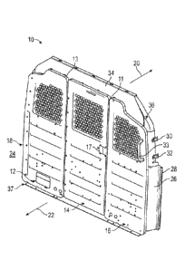
vehicles, shifts in cargo that may cause loads to move from the cargo area to
the cab area,
and in the case of passenger vehicles, such as, for example police vehicles,
isolates the
passengers from the officers so that the passengers can be transported with
minimal risk
to the officers.
[0003] There is an increasing complexity in the design of commercial and
passenger
vehicles. For example, with new vehicle safety systems, the B pillar has been
used to
store side impact air bags. In addition, side impact crash sensors and the
accompanying
control modules for such systems may also be stored in the B pillar. In the
case of Lane
Detection Systems, the B pillar is often utilized to store radar or lidar
systems, as well as
the accompanying control modules to provide alerts to the vehicle operator as
necessary.
[0004] The
wiring for vehicles has also increased in complexity. The roof bows,
which used to provide structural support, and now used as conduits wherein
wiring is run
to power the safety systems and for other systems within the vehicle.
[0005] The use of the B pillars and the roof bows for safety systems and
wiring
conduits has greatly reduced their ease of use as mounting structures for
cargo partition
systems. Indeed, mounting a cargo area partition to the roof bow may risk
damaging the
wiring that runs through the roof bows. Moreover, attaching a partition
directly to the B
pillar may damage the safety systems stored therein and further may interfere
with the
deployment of air bags stored in the B Pillar.
1
CA 2883727 2019-11-19
[0006] There is a need for a cargo or vehicle compartment partition that
is rigidly
mountable to a vehicle and does not interfere with the wiring in the roof bows
or in the
safety systems that are stored in the B pillar.
[0007] In one embodiment, the present disclosure is a modular
construction of
partition panels combined with a structural footer rail, at least one close
out wing, at least
one header panel, optional gaskets to provide sound deadening between the
cargo area
and the operator area of the vehicle interior, and a structural reinforcing
hoop to provide
rigidity to the partition structure and create a "box" structure to the
partition.
BRIEF DESCRIPTION OF THE DRAWINGS
[0008] FIG. 1 is a front perspective view of one construction of a
modular partition of
the present disclosure;
[0009] FIG. 2 is a rear perspective view of the modular partition of
Figure 1;
[0010] FIG. 3 is a detailed view of the modular partition of Figure 1
showing the
orientation of the partition to a vehicle roof bow;
[0011] FIG. 4 is a cut away side view of a vehicle equipped with a
modular portion
system.
DETAILED DESCRIPTION
[0012] Turning now to the drawings wherein like numbers refer to like
structures, and
particularly to Figures 1, 2 and 4, Figure 4 is a representation of vehicle 44
in cutaway
view depicting a vehicle interior space 24 having a cargo partition system 10
separating
the vehicle interior space 24 into a cargo side 22 and a cab side 20. Figures
1 and 2
depict a schematic representation of the modular cargo partition system 10
comprised of
individual bulkhead partition panels 12, 14 and 16 as shown or an optional
single
bulkhead partition panel to create partition 18, mounted in a footer rail 37
to create the
partition separating cab side 20 from cargo side 22 of a vehicle interior
space 24.
[0013] The panels are configured to fit within the contours of the
vehicle interior
space of, for example, a vehicle 44 within which it is mounted. In that
regard, if
individual panels are utilized, panel 14 may be pivotally joined as by hinges
13 relative to
2
CA 2883727 2019-11-19
panel 12 so that it is possible to open panel 14 about the hinges to permit
access from the
cab side to the cargo side. A stop 11 is provided at an edge of the panel 16
to limit the
swing movement of the panel 14 about the hinge and permit the panel to rest
against the
stop when it is in the closed position. In the embodiment shown, the panel 14
may be
swingably opened toward the cargo side 20. It follows that, in this
configuration, stop 11
would have an orientation to accommodate that movement into the cargo area and
stop
movement of the panel into the cab section. However, it is also contemplated
that panel
14 could be swingably opened into the cab side, depending upon the orientation
of the
hinge. A latch 17 is provided on the cab side of the panel 14 and on the cargo
side of the
panel. Any type of latch mechanism is contemplated as long as it can be opened
to
permit the panel to move about the hinge, and then latch the panel into place
with the
panel is closed. The panel 16 may be equipped with complimentary structure to
engage
the latch as may be well known to those skilled in the art. Note that the
panel nearest the
vehicle access door may further be equipped with a hand grip 33 to permit
easier ingress
and egress to the cargo space of the vehicle interior.
[0014] Turning to Figure 2, the footer rail 37 is further adapted to
accommodate the
movement of the panel 14. Flanges 19 and 21 are provided to cooperatively
engage
panels 12 and 16, respectively. The flanges may be equipped with apertures 45
through
which fasteners such as screws or bolts may be passed to affix panels 12 and
16 onto the
footer rail 37. The footer rail further may have a sill 23 extending the width
25 of the
panel 14 to permit ingress and egress through the partition when the panel 14
is opened.
[0015] The panels as shown have windows 27, 29 and 31 to permit air to flow
between the cab portion and the cargo portion of the vehicle interior space.
The windows
also permit viewing between the cab portion and the cargo portion of the
vehicle interior
space.
[0016] The partition system as depicted may include at least one wing
close out panel
26 that may include an optional gasket 28, and may further include attachment
brackets
30, 32 to facilitate attachment of the structural rail 36 to the vehicle B
pillar 48. The
attachment of the wing(s) to the vehicle B pillar is especially important as
the B pillar
often stores safety systems such as air bags, lane detection equipment etc.
The attachment
3
CA 2883727 2019-11-19
flanges may interact with complimentary structures on the B pillar to permit
the wing to
be secured into place without disturbing the B pillar stored safety systems. A
gasket may
be interposed between the wing flange and the B pillar to help control noise
etc when the
wing is attached to the B pillar. The attachment of the wing to the B pillar
may be
accomplished by passing a suitable number of screw, bolts or other attachments
through
the flange apertures and into cooperation with complimentary structures such
as
apertures, bolts etc., in the B pillar.
[0017] The system further includes header closeout panel 34 to facilitate
attachment of
the bulkhead partition panels to the header panel and to the structural rail
36 in a manner
that does not disturb the vehicle headliner 38 or the wiring that may be
routed through the
vehicle roof bow 40. The header close out panel is further equipped with
flange 46
against which the panels 12 and 16 are secured, either by fasteners, screws,
bolts etc., and
against which panel 14 may rest if it is an openable partition or, if it is
not openable,
panel 14 may also be secured so that the entire partition is unitary and
presents a boxlike
structure when affixed to the B pillar.
[0018] The system is constructed in such a manner as to provide a box
like structure
for mounting in the vehicle. This is achieved by the cooperation of a footer
rail and a
structural reinforcing bow. The footer rail is attached to a vehicle floor by
any suitable
attachment such as screw or bolts. The bulkhead panels are mounted to a footer
rail. The
structural bow is secured to the attachment brackets. The attachment brackets
are oriented
along the structural bow so that attachment fasters such as screws, bolts etc
passed
through the attachment brackets engage complimentary structures in the vehicle
roof
bows, The cooperation of the footer rail, structural bracket and the panels
creates a "box
like" structure that may be mounted at any convenient space in the vehicle
interior to
separate the cab from the cargo area. The footer rail may be mounted to the
floor where
the risk of damaging safety systems is greatly reduced. The structural bow
holds the
panel system rigid such that the wing close out panels can be secured to the B
Pillar and
the header closeout can be secured to the structural rail 36 without
disturbing the vehicle
headliner or roof bow wiring routed therein.
4
CA 2883727 2019-11-19
[0019] Figure 3 is a detailed cutaway view of a roof bow showing a no drill
area 41 of
the roof bow 40 and the vehicle headliner 38. Similarly, the wings may have
apertures to
fasten the wings to the vehicle structure without damaging the vehicle safety
systems in
the B Pillar.
[0020] While one embodiment has been shown, the words used in the
specification are
words of description and not words of limitation. Those skilled in the art
understand that
many variations and modification can be made without departing from the scope
of the
disclosure. The scope of protection being sought is defined by the following
claims rather
than the described embodiments in the foregoing description. The scope of the
claims
should not be limited by the described embodiments set forth in the examples
but should
be given the broadest interpretation consistent with the description as a
whole.
CA 2883727 2019-11-19