Note: Descriptions are shown in the official language in which they were submitted.
1
SKI FOR A SNOW VEHICLE
TECHNICAL FIELD
[0001] This relates to a ski for a vehicle designed to travel on snow.
BACKGROUND
[0002] Snow vehicles, particularly sport vehicles, generally have a
driver, such as a track,
and one or more skis used to steer the vehicle. As the vehicle often
encounters obstacles, the ski is
designed to be articulating to overcome the obstacles. In addition, the ski is
generally designed to
have a large surface area to support the vehicle on the snow, and one or more
blades or runners to
provide some control over the direction of the vehicle, particularly when the
ski is controlled by
the steering mechanism.
SUMMARY
[0003] In one aspect, there is provided a ski for a snow vehicle,
comprising a ski body having
an upper surface and a lower surface. The lower surface comprises a lift
surface and a central
runner, the central runner extending along a length of the ski body and
downward from the lift
surface relative to the upper surface. There is a spindle having a first end
and a second end. A ski
attachment attaches the first end of the spindle to the ski body at an
attachment point along the ski
body. The ski attachment comprises a pivot point that is positioned in line
with the central runner
and below at least a portion of the lift surface relative to the upper surface
at the attachment point.
[0004] According to another aspect, the central runner comprises a
hollow cavity accessible
from the upper surface of the ski body, the pivot point being positioned
within the hollow cavity.
[0005] According to another aspect, the ski body further comprises one or
more side runners
that extend parallel to the central runner.
[0006] According to another aspect, the lift surfaces are concave
relative to the first runner
along a width of the lift surface.
[0007] According to another aspect, the ski further comprises a snow
vehicle attachment
Date Recue/Date Received 2022-04-07
2
that connects the second end of the spindle to the snow vehicle. The snow
vehicle attachment may
comprise a forks attachment and an axle attachment that attaches to a forks
and axle of a
motorcycle converted to a snow vehicle.
[0008] In one aspect, there is provided a ski for a snow vehicle,
comprising a ski body having
a first runner and first and second lift surfaces that extend laterally from
the first runner, the first
runner extending below the first and second lift surfaces and extending along
a length of the ski
body. There is a spindle having a first end and a second end. A ski body
attachment connects the
first end of the spindle to the ski body. The ski body attachment has a pivot
point that is positioned
in line with the first runner and below at least a portion of the lift
surfaces, the spindle extending
above the ski body when attached. A snow vehicle attachment connects the
second end of the
spindle to the snow vehicle.
[0009] According to an aspect, the first runner comprises a hollow
cavity accessible from an
upper surface of the ski body, the pivot being positioned within the hollow
cavity.
[0010] According to an aspect, the ski body further comprises one or
more second runners
carried by and extending below at least one of the first and second lift
surfaces, the one or more
second runners being parallel to the first runner.
[0011] According to an aspect, the lift surfaces are concave relative
to the first runner along
a width of the lift surface, and the pivot point is positioned below an apex
of the lift surface.
[0012] According to an aspect, the snow vehicle attachment comprises a
forks attachment
and an axle attachment that attaches to a forks and axle of a motorcycle
converted to a snow
vehicle.
[0012A] According to an aspect, there is provided a ski assembly for a
snow vehicle,
comprising: a ski body having an upper surface and a lower surface, the lower
surface comprising
a lift surface and a runner, the runner extending along a length of the ski
body and downward from
the lift surface relative to the upper surface; a spindle having a first end
and a second end attachable
Date Recue/Date Received 2022-04-07
2a
to the .snow vehicle; and a ski attachment that attaches the first end of the
spindle to the Ski body
at an attachment point along the ski body, the ski attachment comprising a
pivot point that is
positioned it line with the runner and below at least a portion of the lift
surface relative to the
upper surface at the attachment point such that when the second end Of the
spindle is attached to
the snow vehicle, the ski body is permitted to pivot about the pivot point
such that the ski body
changes pivotal orientation relative to the spindle and the snow vehicle;
while the spindlemaintains
a constant pivotal orientation relative to the snow vehicle.
[0012B] According to all aspect, there is provided a ski assembly for
snow vehicle,
comprising: a ski body having a first runner and first and second lift
surfaces that extend laterally
from the first runner, the first runner extending below the first and second
lift surfaces and along
a length of the ski body; a spindle having a first end and a second ,end, the
second end being
connectable to the snow vehicle; a snow vehicle attachment to connect the
second end of the
spindle to the snow vehicle; and aski body attachment to connect the first end
of the .spindle .tithe
ski body, the ski body attachment having a pivot point thatis positioned in
line with the first runner
and below at least a portion of the lift-surfaces, the spindle extending above
the ski body when
attached such that when thesecond end of the spindle is attached to the snow
vehicle, the ski body
is permitted to pivot about the pivot point such that the ski body changes
pivotal orientation relative
=to the spindle and the snow vehicle, while the spindle maintains a constant
pivotal orientation
relative to the snow vehicle.
[0013] The features described above may be combined in any reasonable
manner unless the
features are mutually exclusive.
BRIEF DESCRIPTION OF THE DRAWINGS
[0014] These and other features will become more apparent from the
following
Date Recue/Date Received 2022-11-23
3
description in which reference is made to the appended drawings, the drawings
are for the
purpose of illustration only and are not intended to be in any way limiting,
wherein:
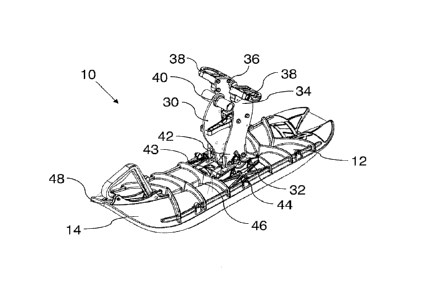
FIG. 1 is a perspective view of a ski.
FIG. 2 is a side elevation view in section of the ski of FIG. I.
FIG. 3 is a front plan view of the ski of FIG. 1.
FIG. 4 is a side elevation view of the ski attached to a snow vehicle.
FIG. 5 is a right side elevation view of the ski of FIG. 1.
FIG. 6 is a bottom view of the ski of FIG. 1.
DETAILED DESCRIPTION
[0015] A ski for a snow vehicle generally identified by reference numeral
10 will now
be described with reference to FIG. 1 through 4.
[0016] Referring to FIG. 4, ski 10 is designed to be attached to a
snow vehicle 100. The
ski 10 as described and shown is particularly designed to be used on a ski
vehicle 100 that is made
from converting a motorcycle, such that it attaches to the forks 102 and axle
104 of motorcycle
100. It has been found that the performance characteristics of ski 10 are
particularly suited for this
type of vehicle. However, it will be understood that the design features
described may be adapted
to other types of snow vehicles and that benefits may also be achieved for
these other snow
vehicles. For example, ski 10 may be used with a traditional snowmobile or
other powered vehicle
that uses skis. The term "snow vehicle" may also include non-powered vehicles
that use skis, such
as sleds, toys, snow scooters, etc.
[0017] Referring to FIG. 2, ski 10 has a ski body 12 with an upper
surface 14 and a lower
surface 16. Lower surface 16 has a lift surface 18 and a central runner 20. As
shown, lift surface
18 is divided into two sections by central runner 20. Preferably, lift surface
18 has a slightly
concave shape relative to the ground on each side of central runner 20 and,
referring to FIG. 3, a
slightly convex shape along the length of ski body 12. Central runner 20
extends along the length
of ski body 12 and depends from ski body 12 such that it extends downward
below lift surface
18. As is known in the art, lift surface 18 is used generally to provide
vertical support to ski body
12, while runner 20 is used to provide lateral control used to keep the snow
vehicle stable and to
Date Recue/Date Received 2022-04-07
3a
steer the snow vehicle when ski body 12 is turned. Preferably, central runner
20 extends along the
entire length of ski body 12 to increase the available
Date Recue/Date Received 2022-04-07
4
surface area to engage with the snow. In addition to central runner 20, there
are preferably side
runners 22 that extend generally parallel to the direction of central runner
20 to increase lateral
stability and control of ski 10. As shown, central runner 20 and side runners
22 are formed as
part of ski body 12 and are formed by shaping ski body 12, such that runners
20 and 22 extend
downward, and engage the snow during operation at a lower point than lift
surface 18. It will
be understood that other designs for skis may also be used, such as runners
that are
manufactured separately and attached adjacent to lift surfaces 18, or
additional parts that are
attached to runners 20 and 22, such as to increase the size or to reinforce
runners 20 and 22.
.. [0018] The size, shape and other design characteristics, such as the
structural reinforcement,
etc., of ski body 12 may be designed based on the preferences of the user and
based on well-
known principles. Furthermore, it will be understood that, while the depicted
design with three
runners 20 and 22 is preferred for a variety of reasons, there may be other
designs used. For
example, central runner 20 may not be positioned at the middle of ski body 12,
but may be
offset with appropriate design changes, or the ski body 12 may include more
than one runner
20. In the depicted embodiment, there is a general distinction between lift
surfaces 18 and
runners 20 and 22. It will be understood that the overall design of ski 10 may
be modified
based on the intended use, including vehicle characteristics, riding styles,
and riding conditions
from what is shown. As these design principles are well known, they will not
be described
further.
[0019] Referring to FIG. 4, a spindle 30 with a first end 32 and a second end
34 is used to
attach ski body 12 to snow vehicle 100. Referring to FIG. 1 and 4, there is a
snow vehicle
attachment 36 at second end 34 of spindle 30 that attaches spindle 30 to snow
vehicle 100. As
snow vehicle 100 is a motorcycle that has been converted, snow vehicle
attachment 36 includes
a forks attachment 38 and an axle attachment 40 to attach to forks 102 and
axle 104. While
spindle 30 as depicted is particularly designed for a motorcycle conversion
kit, it will be
understood that it may take various configurations depending on the type of
snow vehicle 100
that it is being mounted to. In particular, spindle 30 may be considered to be
any component
that mounts ski body 12 to snow vehicle 100 or a steering mechanism or other
vehicle control
Date Recue/Date Received 2022-04-07
5
device that attaches ski body 12 to snow vehicle 100. Similarly, snow vehicle
attachment 36
may also be modified to fit the type of snow vehicle 100.
[0020] Referring to FIG. 3, there is a ski attachment 42 that attaches first
end 32 of spindle 30
.. to ski body 12 at an attachment point 43. As shown, ski attachment 42 has a
pivot point 44 that
in line with central runner 20 and is positioned below lift surface 18, or at
least a portion of
lift surface 18. Ideally, pivot point 44 will be as low as is practical, such
as about half way
down the entire height of ski body 12, including runner 20 and lift surface
18. As a minimum,
when lift surface 18 is curved, pivot point 44 will be positioned between the
apexes of lift
.. surface 18. In the embodiment depicted in FIG. 1 and 2, ski body 12 has
been shaped to form
central runner 20 such that an inner cavity 46 is formed on its top side and
such that pivot point
44 may be positioned within cavity 46 and attached to ski body 12 therein. As
can be seen in
FIG. 1 and 3, pivot point 44 is preferably not "below" lift surface 18 in the
sense that it is
exposed to the surface on which ski body 12 travels. While this may be
possible, it would
disrupt the lines of central runner 20, and risk unnecessary damage or fouling
of pivot point
44. Instead, the position of pivot point 44 is merely lower than the surface
that rides on the
snow. Pivot point 44 is oriented such that it permits ski body 12 to rotate
about an axis that is
perpendicular to the length of ski body 12 and in the plane in which ski body
12 generally
travels. While there may be other structural components that help support ski
body 12 on
spindle 30, pivot point 44 is designed such that ski body 12 is able to pivot
relative to spindle
in order to allow the tip 48 of ski body 12 to move vertically during use. By
positioning
pivot point 44 below lift surface 18, or at least below upper surface 14, ski
body 12 is more
responsive to changing contours in the landscape. As will be understood, as
the tip 48 of ski
body 12 encounters an obstacle, the force applied to the tip by the obstacle
will result in a
25 greater moment arm about pivot point 44 when it is positioned below lift
surface 18 than when
it is positioned above lift surface 18, which results in ski body 12
responding to the obstacle
more quickly.
[0021] Referring to FIG. 5 and 6, tip 48 preferably has a particular shape
that assists with
30 lifting ski 12 on top of the snow. As can be seen, tip 48 has a width
that is greatest before or
at the point at which runners 22 start. Ski 12 then tapers to a narrower width
after runners 22
Date Recue/Date Received 2022-04-07
CA 02883734 2015-03-04
6
begin. As shown, ski 12 reaches its narrowest point around the middle of
central runner 20,
which generally corresponds to the position of attachment point 43. In
addition, the bottom
surface 16 at tip 48 has a concave, spoon-shaped surface. It is believed that
this shape of tip
48 provides additional lift to ski 12 relative to other ski profiles based on
the following
mechanism. The shape of tip 48 allows a certain volume of snow to be collected
as ski moves
forward. As ski 12 continues to move forward, runners 22 maintain the amount
of snow
below ski 12. The decreasing width of ski 12, combined with the amount of snow
being
maintained between runners 20 is believed to apply an upward force to bottom
surface 16 of
ski 12 relative to other ski designs that assist ski 12 in riding on the top
of the snow surface.
[0022J In this patent
document, the word "comprising" is used in its non-limiting sense to
mean that items following the word are included, but items not specifically
mentioned are not
excluded. A reference to an element by the indefinite article "a" does not
exclude the
possibility that more than one of the elements is present, unless the context
clearly requires
that there be one and only one of the elements.
[0023] The scope of
the following claims should not be limited by the preferred
embodiments set forth in the examples above and in the drawings, but should be
given the
broadest interpretation consistent with the description as a whole.