Note: Descriptions are shown in the official language in which they were submitted.
CA 02883748 2015-03-03
WO 2014/046797 PCT/US2013/053600
ELECTROCHEMICAL CO-PRODUCTION OF CHEMICALS UTILIZING A HALIDE SALT
TECHNICAL FIELD
[0001 ]The present disclosure generally relates to the field of
electrochemical
reactions, and more particularly to methods and/or systems for electrochemical
co-production of a carboxylic acid employing a recycled reactant.
BACKGROUND
[won The combustion of fossil fuels in activities such as electricity
generation,
transportation, and manufacturing produces billions of tons of carbon dioxide
annually. Research since the 1970s indicates increasing concentrations of
carbon
dioxide in the atmosphere may be responsible for altering the Earth's climate,
changing the pH of the ocean and other potentially damaging effects. Countries
around the world, including the United States, are seeking ways to mitigate
emissions of carbon dioxide.
[0002] A mechanism for mitigating emissions is to convert carbon dioxide into
economically valuable materials such as fuels and industrial chemicals. If the
carbon dioxide is converted using energy from renewable sources, both
mitigation
of carbon dioxide emissions and conversion of renewable energy into a chemical
form that can be stored for later use will be possible.
SUMMARY
[0003] The present disclosure includes a system and method for co-producing a
first product and a second product. The system may include a first
electrochemical
cell, at least one second reactor, and an acidification chamber. The method
and
system for co-producing a first product and a second product may include co-
producing a carboxylic acid and at least one of an alkene, alkyne, aldehyde,
ketone, or an alcohol while employing a recycled halide salt.
1
CA 02883748 2015-03-03
WO 2014/046797 PCT/US2013/053600
[0004] It is to be understood that both the foregoing general description and
the
following detailed description are exemplary and explanatory only and are not
necessarily restrictive of the present disclosure. The accompanying drawings,
which are incorporated in and constitute a part of the specification,
illustrate
subject matter of the disclosure. Together, the descriptions and the drawings
serve to explain the principles of the disclosure.
BRIEF DESCRIPTION OF THE DRAWINGS
[0005] The numerous advantages of the disclosure may be better understood by
those skilled in the art by reference to the accompanying figures in which:
FIG. 1A is a block diagram of a system in accordance with an embodiment of
the present disclosure;
FIG. 1B is a block diagram of a system in accordance with an embodiment of
the present disclosure;
FIG. 2A is a block diagram of a system in accordance with another
embodiment of the present disclosure;
FIG. 2B is a block diagram of a system in accordance with an embodiment of
the present disclosure;
Fig. 3A is a block diagram of a system in accordance with an additional
embodiment of the present disclosure;
FIG. 3B is a block diagram of a system in accordance with an embodiment of
the present disclosure; and
FIG. 4 is a block diagram of a system in accordance with another additional
embodiment of the present disclosure.
DETAILED DESCRIPTION
[0006] Reference will now be made in detail to the subject matter disclosed,
which
is illustrated in the accompanying drawings.
2
CA 02883748 2015-03-03
WO 2014/046797 PCT/US2013/053600
[0007] The systems and methods of the present disclosure may include an
electrochemical cell that includes an input of a recycled reactant to co-
produce
valuable products at both the cathode and anode sides of the electrochemical
cell.
In one embodiment, carbon dioxide may be reduced in a catholyte region of the
electrochemical cell to a carboxylate, and a halide salt is oxidized in an
anode
region of the electrochemical cell to a halogen. The carboxylate may be fed
into
an acidification chamber along with a hydrogen halide to form a carboxylic
acid
and the halide salt. The halide salt is then recycled to the anode region of
the
electrochemical cell. The halogen produced in the anode compartment is
subsequently fed to a second reactor along with an alkane, alkene, aromatic,
or
other organic compound to produce a halogenated compound and a hydrogen
halide. The halogenated compound may be further treated in a third reactor to
produce an alkene, alkyne, aldehyde, ketone, or an alcohol. The third reactor
also
produces additional hydrogen halide, which may be fed to the acidification
chamber. In one embodiment, the method and system of the present disclosure
may use a source of carbon dioxide, an alkane, alkene, aromatic or other
organic
compound in order to efficiently produce an alkene, alkyne, aldehyde, ketone,
or
an alcohol and a carboxylic acid with the recycling of halide salt. The
organic
chemical partially oxidized in the process may serve as the source of hydrogen
for
the reduction of carbon dioxide and acidification of the resulting carboxylic
acid.
The organic may thereby be indirectly oxidized by carbon dioxide while the
carbon
dioxide is reduced by the organic such that two or more products are made
simultaneously. Advantageously, the halogen employed to partially oxidize an
organic and provide hydrogen to the reduction of carbon dioxide or
acidification of
M-Carboxylate may be recycled.
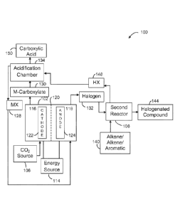
[0008] Referring to FIG. 1A, a block diagram of a system 100 in accordance
with an
embodiment of the present disclosure is shown. System (or apparatus) 100
generally includes an electrochemical cell 102. Electrochemical cell 102 may
also
be referred as a container, electrolyzer, or cell. Electrochemical cell 102
may be
implemented as a divided cell. The divided cell may be a divided
electrochemical
3
CA 02883748 2015-03-03
WO 2014/046797 PCT/US2013/053600
cell and/or a divided photo-electrochemical cell. Electrochemical cell 102 may
include a first region 116 and a second region 118. First region 116 and
second
region 118 may refer to a compartment, section, or generally enclosed space
and
the like without departing from the scope and intent of the present
disclosure.
First region 116 may include a cathode 122. Second region 118 may include an
anode 124. First region 116 may include a catholyte whereby carbon dioxide
from
carbon dioxide source 106 is included in the catholyte. Second region 118 may
include an anolyte which may include an MX 128 where M is at least one cation
and
X is selected from a group consisting of F, Cl, Br, I and mixtures thereof. An
energy source 114 may generate an electrical potential between the anode 124
and the cathode 122. The electrical potential may be a DC voltage. Energy
source
114 may be configured to supply a variable voltage or constant current to
electrochemical cell 102. Separator 120 may selectively control a flow of ions
between the first region 116 and the second region 118. Separator 120 may
include an ion conducting membrane or diaphragm material.
[0009] Electrochemical cell 102 is generally operational to reduce carbon
dioxide in
the first region 116 to an M-carboxylate 130 recoverable from the first region
116,
while producing a halogen 132 recoverable from the second region 118.
[0010] Carbon dioxide source 106 may provide carbon dioxide to the first
region
116 of electrochemical cell 102. In some embodiments, the carbon dioxide is
introduced directly into the region 116 containing the cathode 122. It
is
contemplated that carbon dioxide source 106 may include a source of multiple
gases in which carbon dioxide has been filtered from the multiple gases.
[0011] It is contemplated that the electrochemical cell 102 may include a
first
product extractor (not shown) and second product extractor (not shown).
Product
extractors may implement an organic product and/or inorganic product
extractor.
The first product extractor (not shown) is generally operational to extract
(separate) a product from the first region 116. The second product extractor
(not
4
CA 02883748 2015-03-03
WO 2014/046797 PCT/US2013/053600
shown) may extract the second product from the second region 118. It is
contemplated that the first product extractor and/or second product extractor
may be implemented with electrochemical cell 102, or may be remotely located
from the electrochemical cell 102. Additionally, it is contemplated that first
product extractor and/or second product extractor may be implemented in a
variety of mechanisms and to provide desired separation methods, such as
fractional distillation, without departing from the scope and intent of the
present
disclosure. It is further contemplated that extracted product may be presented
through a port of the system 100 for subsequent storage and/or consumption by
other devices and/or processes.
[0012] An anode side of the reaction occurring in the second region 118 of the
electrochemical cell 102 may include an input of a recycled reactant of MX
128.
The MX 128 may include a halide salt which may be a byproduct of a reaction of
acidification chamber 134. For example, the MX 128 may include a halide salt
where M is a cation including at least one of Li, Na, K, Cs, Mg, Ca, hydrogen
ions,
tetraalkyl ammonium ions such as tetrabutylamnnoniunn, tetraethylamnnoniunn,
choline, and tetraalkylphosphoniunn ions such as tetrabutylphosphoniunn,
tetraethylphosphoniunn, and in general, R1R2R3R4N or R1R2R3R4P where R1 to R4
are
independently alkyl, cycloalkyl, branched alkyl, and aryl, and X is selected
from a
group consisting of F, Cl, Br, I and mixtures thereof. The anode side of the
reaction may produce a halogen 132 which may be presented to second reactor
108.
[0013] System 100 may include second reactor 108 which may receive halogen 132
produced by the second region 118 of the electrochemical cell 102 after
separation
from the second region via a second product extractor. Second reactor 108 may
react halogen 132 with an alkane, alkene, aromatic, or other compound 140 to
produce a halogenated product or halogenated intermediate compound 144 and HX
148. The HX 148 produced in the reaction may be another recycled reactant
which
may be recycled to the acidification chamber 134 as an input feed to the
CA 02883748 2015-03-03
WO 2014/046797 PCT/US2013/053600
acidification chamber 134. Examples of halogenated products include
nnonohalogenated, polyhalogenated, and perhalogenated compounds to include
chloroform, hydrofluorocarbons, bronnoalkanes, vinyl chloride, vinyl bromide,
vinyl
fluoride, vinylidene fluoride, tetrafluorethane, bronnobenzene,
dibronnobenzene,
bronnoethane, dichloroethane, allyl chloride, chlorophenol, fluorosurfactants,
tetrafluoroethylene, hexafluoropropylene, difluoronnethane, or
pentafluoroethane.
[0014] The acidification chamber 134 of system 100 reacts the HX 148 with the
M-
carboxylate 130 to produce carboxylic acid 150 and MX 128, which is recycled
as an
input to the second region 118. The carboxylic acid 150 may be further reacted
in
an additional reactor with H2 to produce at least one of a more reduced
compound. The carboxylic acid 150 may also be reacted with an alcohol to make
an ester or diester or be used in other chemical processes. The M-carboxylate
130
may include M-oxalate, M-formate, M-glyoxylate, M-glycolate, or M-acetate in
one
embodiment.
In one embodiment shown in FIG. 1B, the system 100 includes an additional
reactor, shown as third reactor 152. Halogenated compound 144 may be fed to
third reactor 152. In one embodiment, the third reactor 152 is a
dehydrohalogenation reactor. Third reactor 152 may perform a
dehydrohalogenation reaction of the halogenated compound 144 under specific
conditions to produce a second product 156 of an alkene or alkyne. Examples of
products derived from the partial oxidation via halogenation and
dehalogenation in
the second and third reactors are in Table 1 below.
6
CA 02883748 2015-03-03
WO 2014/046797 PCT/US2013/053600
Organic Feed Oxidation Product(s)
Methane Methanol, formaldehyde, formic acid, ethylene,
longer chain compounds such as ethane
Ethane Ethanol, acetaldehyde, acetic acid, ethylene
glycol, ethylene, acetylene, longer chain
compounds such as butane
Ethene (Ethylene) Acetylene
Propane Propanol, isopropanol, propanone, acetone,
propanoic acid, lactic acid, propylene glycol,
propylene
Butane Butanol, butane, butadiene
Isobutane Isobutanol, isobutylene
Benzene Phenol
Toluene Benzyl alcohol, benzyl aldehyde, benzoic acid
Xylene Terephthalic acid, isophthalic acid, phthalic acid
Ethyl benzene Styrene
Table 1
[0015] An example implementation of the system 100 shown in FIGS. 1A and 1B is
shown in FIG. 2A. A system 200 for generating ethylene 204 and oxalic acid 206
from a recycled reactant of tetrabutylannnnoniunn bromide (TBA-bromide) 208
and
carbon dioxide 106 is provided. Recycled reactant comprised of
tetrabutylannnnoniunn bromide (TBA-bromide) 208 is fed into the second region
118
of electrochemical cell 102, forming bromine 210. The bromine 210 is extracted
from the second region 118 and fed into second reactor 108 where it reacts
with
ethane 212 to form bronnoethane 214 and hydrogen bromide 216. Any byproducts
of the halogenation, such as 1,1 dibronnoethane or 1,2 dibronnoethane, may be
separated and sold as a separate product, hydrogenated back to ethane for
recycle, or catalytically converted to bronnoethane. The hydrogen bromide 216
is
recycled to acidification chamber 134. The bronnoethane 214 is fed into the
third
reactor 152, which may be a dehydrohalogenation reactor. The bronnoethane 214
is
dehydrohalogenated to form ethylene 204.
[0016] The cathode 122 side of the reaction of the embodiment shown in FIG. 2A
includes the reduction of carbon dioxide in the presence of
tetrabutylannnnoniunn
cations from the reaction in the second region 118, to form
tetrabutylannnnoniunn
7
CA 02883748 2015-03-03
WO 2014/046797 PCT/US2013/053600
oxalate 218. The tetrabutylannnnoniunn oxalate 218 is fed into the
acidification
chamber 134 where it reacts with the recycled hydrogen bromide 216 to produce
oxalic acid 206 and tetrabutylannnnoniunn bromide 208. The
tetrabutylannnnoniunn
bromide 208 is recycled to the second region 118. The oxalic acid 206 may be
further reacted in a thermal hydrogenation chamber with H2 to form a more
reduced carbon product, such as glyoxylic acid, glycolic acid, glyoxal,
glycolaldeyde, ethlylene glycol, ethanol, acetic acid, actaldehyde, ethane, or
ethylene.
[0017] In another embodiment shown in FIG. 2B, water 220 may be fed into the
third reactor 152 along with the bronnoethane 214 to produce ethanol 222 and
hydrogen bromide 216.
[0018] A further embodiment of a system in accordance with the present
disclosure
is provided in FIGS. 3A and 3B which includes electrochemical cell 102, second
reactor 108, third reactor 152, and an electrochemical acidification cell 302.
The
system 300 may be used to form an alkane, alkene, alkyne, aldehyde, ketone, or
an alcohol while simultaneously producing a carboxylic acid.
[0019] As shown in FIGS. 3A and 3B, electrochemical cell 102 is generally
operational to reduce carbon dioxide in the first region 116 to M-carboxylate
130
while oxidizing MX 128 in the second region 118 to produce a halogen 132
recoverable from the second region 118. Specifically, an anode side of the
reaction occurring in the second region 118 of the electrochemical cell 102
may
include receiving an input of recycled reactant, MX 128. The anode side of the
reaction may produce a halogen 132 which may be presented to second reactor
108.
[0020] Second reactor 108 may react halogen 132 with an alkane, alkene,
aromatic, or other organic compound 140 to produce a halogenated compound 144
and HX 148. HX 148 may be another recycled reactant which may be recycled to
8
CA 02883748 2015-03-03
WO 2014/046797 PCT/US2013/053600
the electrochemical acidification cell 302 as an input feed to the
electrochemical
acidification cell 302. The halogenated compound 144 may be fed to third
reactor
152. Third reactor 152 may receive a caustic compound 304 generated from the
electrochemical acidification cell 302. The caustic compound 304 may react
with
the halogenated compound 144 in either an aqueous or non-aqueous based
solvent,
such as alcohol, 220 to produce a second product 156 as well as MX 128. If the
reaction occurs in the presence of an aqueous solvent, the second product 156
may
be an alcohol. If the reaction occurs in the presence of a non-aqueous alcohol
based solvent, the second product 156 may be an alkene or alkyne. The MX 128
produced in the third reactor 152 may be recycled to the second region 118 of
the
electrochemical cell 102.
[0021] The caustic compound 304 may include MOH in one embodiment, where M
represents the cation used in the reaction. An example of MOH may include NaOH
or KOH in one embodiment. The caustic compound 304 may include a caustic
metallic base in one embodiment.
[0022] Meanwhile, carbon dioxide source 106 may provide carbon dioxide to the
first region 116 of electrochemical cell 102. In some embodiments, the carbon
dioxide is introduced directly into the region 116 containing the cathode 122.
Carbon dioxide is reduced in the first region 116 and reacts with the ions
from the
anode reaction to produce M-carboxylate 130. The M-carboxylate 130 may be
extracted from the first region 116 and fed into an electrochemical
acidification
cell 302.
[0023] Electrochemical acidification cell 302 may include a first region 316
and a
second region 318. First region 316 and second region 318 may refer to a
compartment, section, or generally enclosed space, and the like without
departing
from the scope and intent of the present disclosure. First region 316 may
include
a cathode 322. Second region 318 may include an anode 324. First region 316
may
include a catholyte comprising water. Second region 318 may include an anolyte
9
CA 02883748 2015-03-03
WO 2014/046797 PCT/US2013/053600
which may include HX 148, which is provided from the second reactor 108 and/or
the third reactor 152 and recycled to the anolyte. An energy source 314 may
generate an electrical potential between the anode 324 and the cathode 322.
Electrochemical acidification cell may also include an acidification region
330. A
first separator 332 and a second separator 333 may selectively control a flow
of
ions between the first region 316, acidification region 330, and the second
region
318. The first separator 332 and the second separator 333 may include an ion
conducting membrane or diaphragm material.
[0024] The electrochemical acidification cell 302 may receive three different
inputs. First, M-carboxylate 130 produced by the first region 116 of the
electrochemical cell 102 may be fed into the acidification region 330 of the
electrochemical acidification cell 302 where it is acidified to form the first
product, carboxylic acid 150, liberating M cations which are transported to
the
first region 316. Second, HX 148 may be recycled from the the second reactor
108
to the second region 318 of electrochemical acidification cell 302 to form
more of
the halogen, liberating H+ cations, or protons, for transport into the
acidification
region 330 . The protons displace or replace the M cations of the M-
carboxalate in
the acidification region 330, which then pass through membrane 332 into region
316 of the catholyte. The halogen 316 produced in the second region 318 of the
electrochemical acidification cell 302 is then removed from the second region
318
and recycled as an input to the second reactor 108. A third input to the
electrochemical acidification cell 302 may include a water source 338 which is
fed
to the first region 316. The water 338 is reduced to H2 and OH- at cathode
322, and
the OH- reacts with the M cations passing from the acidification region
through
membrane 332 to form the caustic compound 304. The caustic compound 304 is
then removed from the first region 316 and may be recycled as an input to the
third reactor 152. H2 336 may also be produced in the first region.
[0025] In one embodiment shown in FIG. 3B, the system 300 may include an
additional reactor including a thermal hydrogenation chamber 334. The thermal
CA 02883748 2015-03-03
WO 2014/046797 PCT/US2013/053600
hydrogenation chamber 334 may react the H2 336 produced in the first region of
the electrochemical acidification cell 302 as well as the first product,
carboxylic
acid 150 produced in the acidification region 330 of the electrochemical
acidification cell 302 to produce a third product 337. The third product may
include glyoxylic acid, glycolic acid, glyoxal, glycolaldehyde, acetic acid,
acetaldehyde, ethanol, ethane, ethylene, or ethylene glycol.
[0026] A further embodiment of a system in accordance with the present
disclosure
is provided in FIG. 4 which includes a first electrochemical cell 102, second
reactor
108, third reactor 152, a second electrochemical cell 402, and a thermal
hydrogenation chamber 334. The system 400 may be used to form an alkene,
alkyne, aldehyde, ketone, or an alcohol (second product 406) while
simultaneously
producing at least one of glyoxylic acid, glycolic acid, glyoxal,
glycolaldehyde,
acetic acid, acetaldehyde, ethanol, ethane, ethylene, or ethylene glycol
(third
product 404).
[0027] As shown in FIG. 4, first electrochemical cell 102 is generally
operational to
reduce carbon dioxide in the first region 116 to M-carboxylate 130 recoverable
from the first region 116, while oxidizing MX 128 in the second region 118 to
produce a halogen 132 recoverable from the second region 118. The halogen 132
may be extracted from the second region 118 and input to a second reactor.
[0028] The second reactor 108 may react the halogen 132 with an alkane,
alkene,
aromatic, or other aromatic compound 140 to produce a halogenated compound
144 and HX 148. HX 148 may then be recycled to an acidification chamber 134 as
an input feed to the acidification chamber 134. The halogenated compound 144
may be fed to third reactor 152. Third reactor 152 may receive a caustic
compound
304 recycled from the second two compartment electrochemical cell 402. The
caustic compound 304 reacts with the halogenated compound 144 in the third
reactor to produce a second product 406 as well as MX 128. The MX 128 may be
11
CA 02883748 2015-03-03
WO 2014/046797 PCT/US2013/053600
recycled as an input feed to a second region 418 of the second electrochemical
cell 402.
[0029] If the reaction of the halogenated compound 144 and the caustic
compound
304 in the third reactor 152 occurs in the presence of water, the second
product
406 may be an alcohol. If the reaction occurs in the presence of a non-aqueous
solvent, such as an alcohol, the second product 406 may be an alkene or
alkyne. In
one embodiment, the second product 406 is ethanol. In another embodiment, the
second product 406 is ethylene. In another embodiment, the second product is
phenol derived from benzene. In yet another embodiment, the second product is
isopropanol derived from propane or propylene.
[0030] The MX 128 produced in the third reactor 152 may be recycled as an
input
feed to a second region 418 of the second electrochemical cell 402. The second
electrochemical cell 402 may include a first region 416 and a second region
418.
First region 416 may include a cathode 422. Second region 418 may include an
anode 424. First region 416 may include a catholyte comprising water. Second
region 318 may include an anolyte which may include MX 128, which is provided
from the third reactor 152 and recycled to the anolyte. An energy source 414
may
generate an electrical potential between the anode 424 and the cathode 422. A
separator 420 may control the flow of ions between the first region 416 and
the
second region 418.
[0031] The second electrochemical cell 402 may receive an input of the MX 128
produced in the third reactor 152 as an input feed to the second region 418 of
the
second electrochemical cell 402 where it is oxidized to produce halogen 132,
liberating M cations to be transported through separator 420 to the first
region
416. Halogen 132 is then removed from the second region 418 and recycled as an
input to the second reactor 108. An additional input to the second
electrochemical
cell 402 may include water 405 which is fed to the first region 416. The water
405
is reduced to H2 and OH- at cathode 422. The OH-hydroxide ions react with M
12
CA 02883748 2015-03-03
WO 2014/046797 PCT/US2013/053600
cations provided by the reaction at the second region 418 to form the caustic
compound 304. The caustic compound 304 is then removed from the first region
416 and may be recycled as an input to the third reactor 152. H2 336 may also
be
produced in the first region, which may be recycled as an input feed to
thermal
hydrogenation chamber 334. Hydrogen for the thermal hydrogenation chamber 334
may be supplied from other sources as well.
[0032] The cathode side of the reaction in the first electrochemical cell 102
consists of the reduction of carbon dioxide provided by carbon dioxide source
106
along with ions from the reaction on the anode side to form M-carboxylate 130.
The M-carboxylate 130 may be removed from the first region 116 and input into
acidification chamber 134. The acidification chamber 134 reacts the HX 148
provided by the second reactor 108 with the M-carboxylate 130 to produce the
carboxylic acid 150 (first product) and MX 128. The MX 128 is recycled as an
input
to the second region. The carboxylic acid 150 is then fed to thermal
hydrogenation
chamber 334.
[0033] The first product, carboxylic acid 150 from the acidification chamber
134 is
then fed to thermal hydrogenation chamber 334 where it reacts with H2 336
provided by the first region 416 of the second electrochemical cell 402 to
produce
the third product 404. Additional H2 may be provided from another source.
[0034] It is contemplated that a receiving feed may include various mechanisms
for
receiving a supply of a product, whether in a continuous, near continuous or
batch
portions.
[0035] It is further contemplated that the structure and operation of the
electrochemical cells 102 and 402 as well as the electrochemical acidification
cell
302 and may be adjusted to provide desired results. For example, the
electrochemical cells may operate at higher pressures, such as pressure above
13
CA 02883748 2015-03-03
WO 2014/046797 PCT/US2013/053600
atmospheric pressure which may increase current efficiency and allow operation
of
the electrochemical cell at higher current densities.
[0036] Additionally, the cathode 122 and anode 124 may include a high surface
area electrode structures with a void volume which may range from 30% to 98%.
The electrode void volume percentage may refer to the percentage of empty
space
that the electrode is not occupying in the total volume space of the
electrode. The
advantage in using a high void volume electrode is that the structure has a
lower
pressure drop for liquid flow through the structure. The specific surface area
of
the electrode base structure may be from 2 cnn2/cnn3 to 500 cnn2/cnn3 or
higher.
The electrode specific surface area is a ratio of the base electrode structure
surface area divided by the total physical volume of the entire electrode. It
is
contemplated that surface areas also may be defined as a total area of the
electrode base substrate in comparison to the projected geometric area of the
current distributor/conductor back plate, with a preferred range of 2x to
1000x or
more. The actual total active surface area of the electrode structure is a
function
of the properties of the electrode catalyst deposited on the physical
electrode
structure which may be 2 to 1000 times higher in surface area than the
physical
electrode base structure.
[0037] Cathode 122 may be selected from a number of high surface area
materials
to include copper, stainless steels, transition metals and their alloys and
oxides,
carbon, and silicon, which may be further coated with a layer of material
which
may be a conductive metal or semiconductor. The base structure of cathode 122
may be in the form of fibrous, reticulated, or sintered powder materials made
from metals, carbon, or other conductive materials including polymers. The
materials may be a very thin plastic screen incorporated against the cathode
side
of the membrane to prevent the membrane 120 from directly touching the high
surface area cathode structure. The high surface area cathode structure may be
mechanically pressed against a cathode current distributor backplate, which
may
14
CA 02883748 2015-03-03
WO 2014/046797 PCT/US2013/053600
be composed of material that has the same surface composition as the high
surface
area cathode.
[0038] In addition, cathode 122 may be a suitable conductive electrode, such
as Al,
Au, Ag, Bi, C, Cd, Co, Cr, Cu, Cu alloys (e.g., brass and bronze), Ga, Hg, In,
Mo,
Nb, Ni, NiCo204, Ni alloys (e.g., Ni 625, NiHX), Ni-Fe alloys, Pb, Pd alloys
(e.g.,
PdAg), Pt, Pt alloys (e.g., PtRh), Rh, Sn, Sn alloys (e.g., SnAg, SnPb, SnSb),
Ti, V,
W, Zn, stainless steel (SS) (e.g., SS 2205, SS 304, SS 316, SS 321),
austenitic steel,
ferritic steel, duplex steel, nnartensitic steel, Nichronne (e.g., NiCr 60:16
(with
Fe)), elgiloy (e.g., Co-Ni-Cr), degenerately doped p-Si, degenerately doped p-
Si:As, degenerately doped p-Si:B, degenerately doped n-Si, degenerately doped
n-
Si:As, and degenerately doped n-Si:B. These metals and their alloys may also
be
used as catalytic coatings on the various metal substrates. Other conductive
electrodes may be implemented to meet the criteria of a particular
application.
For photo-electrochemical reductions, cathode 122 may be a p-type
semiconductor
electrode, such as p-GaAs, p-GaP, p-InN, p-InP, p-CdTe, p-GaInP2 and p-Si, or
an n-
type semiconductor, such as n-GaAs, n-GaP, n-InN, n-InP, n-CdTe, n-GaInP2 and
n-
Si. Other semiconductor electrodes may be implemented to meet the criteria of
a
particular application including, but not limited to, CoS, Mo52, TiB, W52,
SnS, Ag25,
CoP2, Fe3P, Mn3P2, MoP, Ni2Si, MoSi2, W5i2, CoSi2, Ti407, 5n02, GaAs, GaSb,
Ge, and
CdSe.
[0039] Catholyte may include a pH range from 1 to 12 when aqueous solvents are
employed, preferably from pH 4 to pH 10. The selected operating pH may be a
function of any catalysts utilized in operation of the electrochemical cell
102.
Preferably, catholyte and catalysts may be selected to prevent corrosion at
the
electrochemical cell 102. Catholyte may include homogeneous catalysts.
Homogeneous catalysts are defined as aromatic heterocyclic amines and may
include, but are not limited to, unsubstituted and substituted pyridines and
innidazoles. Substituted pyridines and innidazoles may include, but are not
limited
to mono and disubstituted pyridines and innidazoles. For example, suitable
CA 02883748 2015-03-03
WO 2014/046797 PCT/US2013/053600
catalysts may include straight chain or branched chain lower alkyl (e.g., C1-
C1o)
mono and disubstituted compounds such as 2-nnethylpyridine, 4-tertbutyl
pyridine,
2,6 dinnethylpyridine (2,6-lutidine); bipyridines, such as 4,4-bipyridine;
amino-
substituted pyridines, such as 4- dinnethylannino pyridine; and hydroxyl-
substituted
pyridines (e.g., 4-hydroxy-pyridine) and substituted or unsubstituted
quinoline or
isoquinolines. The catalysts may also suitably include substituted or
unsubstituted
dinitrogen heterocyclic amines, such as pyrazine, pyridazine and pyrinnidine.
Other
catalysts generally include azoles, innidazoles, indoles, oxazoles, thiazoles,
substituted species and complex multi-ring amines such as adenine, pterin,
pteridine, benzinnidazole, phenonthroline and the like.
[0040] The catholyte may include an electrolyte. Catholyte electrolytes may
include alkali metal bicarbonates, carbonates, sulfates, phosphates, borates,
and
hydroxides. The electrolyte may comprise one or more of Na2SO4, KCl, NaNO3,
NaCl, NaF, NaCl04, KC104, K2SiO3, CaCl2, a guanidiniunn cation, an H cation,
an
alkali metal cation, an ammonium cation, an alkylannnnoniunn cation, a
tetraalkyl
ammonium cation, a halide anion, an alkyl amine, a borate, a carbonate, a
guanidiniunn derivative, a nitrite, a nitrate, a phosphate, a polyphosphate, a
perchlorate, a silicate, a sulfate, and a hydroxide. In one embodiment,
bromide
salts such as NaBr or KBr may be preferred.
[0041] The catholyte may further include an aqueous or non-aqueous solvent. An
aqueous solvent may include greater than 5% water. A non-aqueous solvent may
include as much as 5% water. A solvent may contain one or more of water, a
protic solvent, or an aprotic polar solvent.
Representative solvents include
methanol, ethanol, acetonitrile, propylene carbonate, ethylene carbonate,
dinnethyl carbonate, diethyl carbonate, dinnethylsulfoxide,
dinnethylfornnannide,
acetonitrile, acetone, tetrahydrofuran, N
,N -dinnethylacetanninde,
dinnethoxyethane, diethylene glycol dinnethyl ester, butyrolnitrile, 1,2-
difluorobenzene, y-butyrolactone, N-methyl-2-pyrrolidone, sulfolane, 1,4-
dioxane,
nitrobenzene, nitronnethane, acetic anhydride, ionic liquids, and mixtures
thereof.
16
CA 02883748 2015-03-03
WO 2014/046797 PCT/US2013/053600
[0042] In one embodiment, a catholyte/anolyte flow rate may include a
catholyte/anolyte cross sectional area flow rate range such as 2 - 3,000
gpnn/ft2 or
more (0.0076 - 11.36 m3/m2). A flow velocity range may be 0.002 to 20 ft/sec
(0.0006 to 6.1 nn /sec). Operation of the electrochemical cell catholyte at a
higher
operating pressure allows more dissolved carbon dioxide to dissolve in the
aqueous
solution. Typically, electrochemical cells can operate at pressures up to
about 20
to 30 psig in multi-cell stack designs, although with modifications, the
electrochemical cells may operate at up to 100 psig. The electrochemical cell
may
operate anolyte at the same pressure range to minimize the pressure
differential
on a separator 120 or membrane separating the two regions.
Special
electrochemical designs may be employed to operate electrochemical units at
higher operating pressures up to about 60 to 100 atmospheres or greater, which
is
in the liquid CO2 and supercritical CO2 operating range.
[0043] In another embodiment, a portion of a catholyte recycle stream may be
separately pressurized using a flow restriction with back pressure or using a
pump,
with CO2 injection, such that the pressurized stream is then injected into the
catholyte region of the electrochemical cell which may increase the amount of
dissolved CO2 in the aqueous solution to improve the conversion yield. In
addition,
micro-bubble generation of carbon dioxide can be conducted by various means in
the catholyte recycle stream to maximize carbon dioxide solubility in the
solution.
[0044] Catholyte may be operated at a temperature range of -10 to 95 C, more
preferably 5 - 60 C. The lower temperature will be limited by the catholytes
used
and their freezing points. In general, the lower the temperature, the higher
the
solubility of CO2 in an aqueous solution phase of the catholyte, which would
help in
obtaining higher conversion and current efficiencies. The drawback is that the
operating electrochemical cell voltages may be higher, so there is an
optimization
that would be done to produce the chemicals at the lowest operating cost. In
addition, the catholyte may require cooling, so an external heat exchanger may
be
employed, flowing a portion, or all, of the catholyte through the heat
exchanger
17
CA 02883748 2015-03-03
WO 2014/046797 PCT/US2013/053600
and using cooling water to remove the heat and control the catholyte
temperature.
[0045] Anolyte operating temperatures may be in the same ranges as the ranges
for
the catholyte, and may be in a range of 0 C to 95 C. In addition, the anolyte
may
require cooling, so an external heat exchanger may be employed, flowing a
portion, or all, of the anolyte through the heat exchanger and using cooling
water
to remove the heat and control the anolyte temperature.
[0046] Electrochemical cells may include various types of designs. These
designs
may include zero gap designs with a finite or zero gap between the electrodes
and
membrane, flow-by and flow-through designs with a recirculating catholyte
electrolyte utilizing various high surface area cathode materials. The
electrochemical cell may include flooded co-current and counter-current packed
and trickle bed designs with the various high surface area cathode materials.
Also,
bipolar stack cell designs and high pressure cell designs may also be employed
for
the electrochemical cells.
[0047] Anode electrodes may be the same as cathode electrodes or different.
Anodes 124, 324, and 424 may include electrocatalytic coatings applied to the
surfaces of the base anode structure. Anolytes may be the same as catholytes
or
different. Anolyte electrolytes may be the same as catholyte electrolytes or
different. Anolyte may comprise solvent. Anolyte solvent may be the same as
catholyte solvent or different. For example, for HBr, acid anolytes, and
oxidizing
water generating oxygen, the preferred electrocatalytic coatings may include
precious metal oxides such as ruthenium and iridium oxides, as well as
platinum
and gold and their combinations as metals and oxides on valve metal substrates
such as titanium, tantalum, zirconium, or niobium. For bromine and iodine
anode
chemistry, carbon and graphite are particularly suitable for use as anodes.
Polymeric bonded carbon material may also be used. For
other anolytes,
comprising alkaline or hydroxide electrolytes, anodes may include carbon,
cobalt
18
CA 02883748 2015-03-03
WO 2014/046797 PCT/US2013/053600
oxides, stainless steels, transition metals, and their alloys and
combinations. High
surface area anode structures that may be used which would help promote the
reactions at the anode surfaces. The high surface area anode base material may
be in a reticulated form composed of fibers, sintered powder, sintered
screens,
and the like, and may be sintered, welded, or mechanically connected to a
current
distributor back plate that is commonly used in bipolar electrochemical cell
assemblies. In addition, the high surface area reticulated anode structure may
also contain areas where additional applied catalysts on and near the
electrocatalytic active surfaces of the anode surface structure to enhance and
promote reactions that may occur in the bulk solution away from the anode
surface such as the reaction between bromine and the carbon based reactant
being
introduced into the anolyte. The anode structure may be gradated, so that the
density of the may vary in the vertical or horizontal direction to allow the
easier
escape of gases from the anode structure. In this gradation, there may be a
distribution of particles of materials mixed in the anode structure that may
contain
catalysts, such as metal halide or metal oxide catalysts such as iron halides,
zinc
halides, aluminum halides, cobalt halides, for the reactions between the
bromine
and the carbon-based reactant. For other anolytes comprising alkaline, or
hydroxide electrolytes, anodes may include carbon, cobalt oxides, stainless
steels,
and their alloys and combinations.
[0048] Separator also referred to as a membrane, between a first region and
second region, may include cation ion exchange type membranes. Cation ion
exchange membranes which have high rejection efficiency to anions may be
preferred. Examples of such cation ion exchange membranes may include
perfluorinated sulfonic acid based ion exchange membranes such as DuPont
Nafion brand unreinforced types N117 and N120 series, more preferred PTFE
fiber
reinforced N324 and N424 types, and similar related membranes manufactured by
Japanese companies under the supplier trade names such as AGC Engineering
(Asahi Glass) under their trade name Flernion . Other multi-layer
perfluorinated
ion exchange membranes used in the chlor alkali industry may have a bilayer
19
CA 02883748 2015-03-03
WO 2014/046797 PCT/US2013/053600
construction of a sulfonic acid based membrane layer bonded to a carboxylic
acid
based membrane layer, which efficiently operates with an anolyte and catholyte
above a pH of about 2 or higher. These membranes may have higher anion
rejection efficiency. These are sold by DuPont under their Nafion trademark
as
the N900 series, such as the N90209, N966, N982, and the 2000 series, such as
the
N2010, N2020, and N2030 and all of their types and subtypes. Hydrocarbon based
membranes, which are made from of various cation ion exchange materials can
also be used if the anion rejection is not as desirable, such as those sold by
Sybron
under their trade name lonac , AGC Engineering (Asahi Glass) under their
Selennion trade name, and Tokuyanna Soda, among others on the market. Ceramic
based membranes may also be employed, including those that are called under
the
general name of NASICON (for sodium super-ionic conductors) which are
chemically
stable over a wide pH range for various chemicals and selectively transports
sodium ions, the composition is Na1+xZr2SixP3-x012, and well as other ceramic
based conductive membranes based on titanium oxides, zirconium oxides and
yttrium oxides, and beta aluminum oxides. Alternative membranes that may be
used are those with different structural backbones such as polyphosphazene and
sulfonated polyphosphazene membranes in addition to crown ether based
membranes. Preferably, the membrane or separator is chemically resistant to
the
anolyte and catholyte and operates at temperatures of less than 600 degrees C,
and more preferably less than 500 degrees C.
[0049] A rate of the generation of reactant formed in the anolyte compartment
from the anode reaction is contemplated to be proportional to the applied
current
to the electrochemical cell. The anolyte product output in this range can be
such
that the output stream contains little or no free bromine in the product
output, or
it may contain unreacted bromine. The operation of the extractor and its
selected
separation method, for example fractional distillation, the actual products
produced, and the selectivity may be adjusted to obtain desired
characteristics.
Any of the unreacted components would be recycled to the second region.
CA 02883748 2015-03-03
WO 2014/046797 PCT/US2013/053600
[0050] Similarly, a rate of the generation of the formed electrochemical
carbon
dioxide reduction product, such as CO, is contemplated to be proportional to
the
applied current to the electrochemical cell. The rate of the input or feed of
the
carbon dioxide source 106 should be fed in a proportion to the applied
current.
The cathode reaction efficiency would determine the maximum theoretical
formation in moles of the carbon dioxide reduction product. It is contemplated
that the ratio of carbon dioxide feed to the theoretical moles of potentially
formed carbon dioxide reduction product would be in a range of 100:1 to 2:1,
and
preferably in the range of 50:1 to 5:1, where the carbon dioxide is in excess
of the
theoretical required for the cathode reaction. The carbon dioxide excess would
then be separated and recycled back to the first region 116.
[0051] In the present disclosure, the methods disclosed may be implemented as
sets of instructions or software readable by a device. Further, it is
understood
that the specific order or hierarchy of steps in the methods disclosed are
examples
of exemplary approaches. Based upon design preferences, it is understood that
the specific order or hierarchy of steps in the method can be rearranged while
remaining within the disclosed subject matter. The accompanying method claims
present elements of the various steps in a sample order, and are not
necessarily
meant to be limited to the specific order or hierarchy presented.
[0052] It is believed that the present disclosure and many of its attendant
advantages will be understood by the foregoing description, and it will be
apparent
that various changes may be made in the form, construction and arrangement of
the components without departing from the disclosed subject matter or without
sacrificing all of its material advantages. The
form described is merely
explanatory, and it is the intention of the following claims to encompass and
include such changes.
21