Note: Descriptions are shown in the official language in which they were submitted.
CA 02883782 2015-02-26
WO 2014/043302 PCT/US2013/059371
1
SYSTEMS AND METHODS FOR DETERMINING FLUID RESPONSIVENESS
FIELD
Embodiments of the present disclosure generally relate to physiological
signal processing, and more particularly, to processing signals to determine
the
fluid responsiveness of a patient.
BACKGROUND
A physician or nurse may use an index of fluid responsiveness to help
determine whether the blood flow of a patient will benefit from additional
fluid
administration. The indices are typically used in connection with ventilated
patients. Such dynamic preload indices may be based on a ventilator-induced
variation of an arterial-line pressure waveform or a photoplethysmographic
("PPG") waveform. The waveform variation may be caused by the following: 1)
a breathing or respiratory cycle induces a cyclic increase in intrathoracic
pressure, which causes 2) a cyclic reduction in venous return, which in turn
causes 3) a cyclic reduction in preload, which causes 4) a cyclic reduction in
cardiac output, which is manifested as 5) a cyclic variation in the arterial
line
pressure or PPG waveform. A large waveform variation indicates that cardiac
output can probably be increased with fluid administration.
However, dynamic indices based on waveform variation are fluid-
response predictive only at relative extremes of large waveform variation
induced by high-tidal-volume ventilation. The use of lung-protective
ventilation
strategies for patients with acute lung injury (ALI) or acute respiratory
distress
syndrome (ARDS) means that many of the most critical patients do not have a
large enough ventilation-induced waveform variation to use as a fluid-
responsiveness measure with certain known techniques. Further still, the
interpretation of dynamic indices or measurements used to arrive at such
interpretations may be confounded by a number of factors. For example,
artifacts introduced into the signal by sources other than the ventilator-
induced
changes in intrathoracic pressure may confound the analysis. As another
example, differences in ventilator mode, circuit impedance, pressure and flow
settings can all affect the size of the ventilator-induced waveform
variability.
Yet further still, because the indices are typically used in connection with
ventilated patients, determinations regarding whether non-ventilated patients
CA 02883782 2015-02-26
WO 2014/043302 PCT/US2013/059371
2
would benefit from fluid administration are made without the benefit of such
indices. A need exists for improved determination of fluid responsiveness.
SUMMARY
Certain embodiments of the present disclosure provide a system that
may include a respiratory detection module, a circulatory detection module,
and
an analysis module. The respiratory detection module is configured to detect
respiratory information representative of respiration of a patient. The
circulatory
detection module is configured to detect circulatory information
representative of
circulation of the patient. The analysis module is configured to obtain a
respiratory waveform based at least in part on the respiratory information,
obtain
a circulatory waveform based at least in part on the circulatory information,
combine the respiratory waveform and the circulatory waveform to provide a
mixed waveform, and isolate a portion of the mixed waveform to identify a
respiratory responsiveness waveform representative of an effect of the
respiration of the patient on the mixed waveform.
The analysis module may be further configured to determine a fluid
responsiveness parameter representative of fluid responsiveness of the patient
using the respiratory responsiveness waveform.
The analysis module may be further configured to combine the
respiratory waveform and the circulatory waveform by multiplication.
In some embodiments, the circulatory detection module may include a
pulse oximetry sensor configured to provide photoplethysmographic information
representative of a photopleythsmographic waveform of the ventilated patient.
In some embodiments, the circulatory detection module may include an arterial
line catheter and a pressure transducer. The pressure transducer is configured
to be associated with the arterial line catheter and to provide blood pressure
information representative of a blood pressure waveform of the ventilated
patient.
The system may be configured to be operably connected to a non-
ventilated patient. In some embodiments, the fluid responsiveness parameter
may be determined with or without the patient being operably connected to a
ventilator.
The respiratory detection module may include a CO2 sensor, and the
respiratory information may correspond to a level of CO2 in exhaled breath.
CA 02883782 2015-02-26
WO 2014/043302 PCT/US2013/059371
3
Certain embodiments provide a method for determining fluid
responsiveness. The method includes obtaining a respiratory waveform
representative of respiratory output of a patient. The respiratory waveform is
based on information obtained from a respiratory detection module. The
method also includes obtaining a circulatory waveform representative of the
circulation of the patient. The circulatory waveform is based on information
provided by a circulatory detection module. The method further includes
combining, at a processing module, the respiratory waveform and the
circulatory
waveform to provide a mixed waveform. Further, the method includes isolating,
at a processing module, a portion of the mixed waveform to provide a
respiratory responsiveness waveform representative of an effect of respiration
on the mixed waveform.
Certain embodiments provide a tangible and non-transitory computer
readable medium including one or more computer software modules. The one
or more computer software modules are configured to direct a processor to
obtain a respiratory waveform representative of a respiratory output of a
patient.
The respiratory waveform is based on information obtained from a respiratory
detection module. Also, the one or more computer software modules are
configured to direct a processor to obtain a circulatory waveform
representative
of the circulation of the ventilated patient. The circulatory waveform is
based on
information provided by a circulatory detection module. Further, the one or
more computer software modules are configured to direct a processor to
combine the respiratory waveform and the circulatory waveform to provide a
mixed waveform, and isolate a portion of the mixed waveform to provide a
respiratory responsiveness waveform representative of an effect of respiration
on the mixed waveform.
Embodiments provide for the isolation of respiration variability (e.g.
variation caused by respiration) in a waveform from other variability (e.g.
variation caused by one or more other sources of potential variability),
thereby
allowing for a more controlled study and determination of fluid
responsiveness.
For example, embodiments provide systems and methods that are configured to
more accurately determine a fluid responsiveness index or indices. Also,
embodiments provide improved predictive value of fluid responsiveness
determinations. Further, embodiments provide systems and methods that are
configured to allow a determination of fluid responsiveness at relatively low
tidal
CA 02883782 2015-02-26
WO 2014/043302 PCT/US2013/059371
4
volume ventilation. Further still, embodiments provide systems and methods
configured to determine a fluid responsiveness index for non-ventilated
patients.
Also, embodiments provide systems and methods configured to determine of
fluid responsiveness for smaller variations of waveforms.
Certain embodiments of the present disclosure may include some, all, or
none of the above advantages. One or more other technical advantages may
be readily apparent to those skilled in the art from the figures,
descriptions, and
claims included herein. Moreover, while specific advantages have been
enumerated above, various embodiments may include all, some, or none of the
enumerated advantages.
BRIEF DESCRIPTION OF THE DRAWINGS
Figure 1 illustrates a schematic diagram, of a system for determining fluid
responsiveness according to an embodiment.
Figure 2 illustrates an isometric view of a photoplethysmogram (PPG)
system according to an embodiment.
Figure 3 illustrates a simplified block diagram of a PPG system in
according to an embodiment.
Figure 4 illustrate a PPG signal according to an embodiment.
Figure 5 illustrates an isometric view of a monitoring system according to
an embodiment.
Figure 6 illustrates a flowchart of a method for determining fluid
responsiveness according to an embodiment.
Figure 7 illustrates a depiction of signal variability according to an
embodiment.
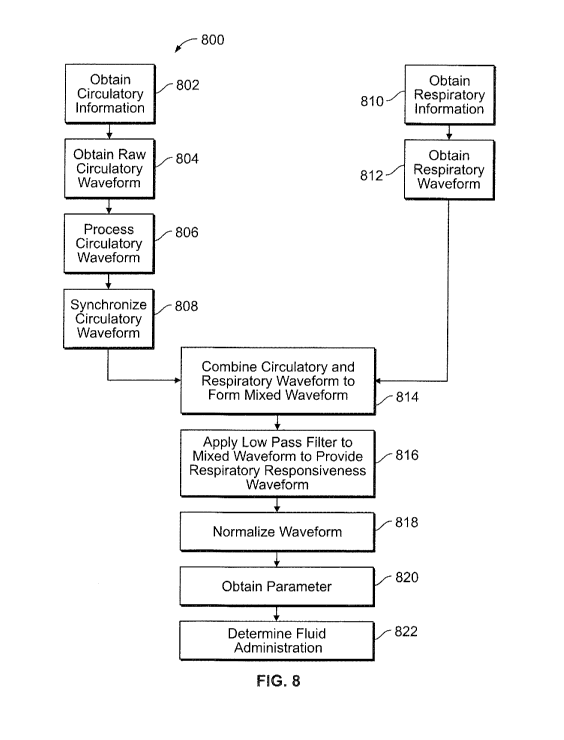
Figure 8 illustrates a flowchart of a method for determining fluid
responsiveness according to an embodiment.
Figures 9a and 9b illustrate a mixed waveform according to an
embodiment.
35
CA 02883782 2015-02-26
WO 2014/043302
PCT/US2013/059371
DETAILED DESCRIPTION
The foregoing summary, as well as the following detailed description of
certain embodiments will be better understood when read in conjunction with
the appended drawings. To the extent that the figures illustrate diagrams of
the
5 functional blocks of various embodiments, the functional blocks are not
necessarily indicative of the division between hardware circuitry. Thus, for
example, one or more of the functional blocks (e.g., processors or memories)
may be implemented in a single piece of hardware (e.g., a general purpose
signal processor or random access memory, hard disk, or the like) or multiple
pieces of hardware. Similarly, the programs may be stand-alone programs, may
be incorporated as subroutines in an operating system, may be functions in an
installed software package, and the like. It should be understood that the
various embodiments are not limited to the arrangements and instrumentality
shown in the drawings.
As used herein, an element or step recited in the singular and proceeded
with the word "a" or "an" should be understood as not excluding plural of said
elements or steps, unless such exclusion is explicitly stated. Furthermore,
references to "one embodiment" are not intended to be interpreted as excluding
the existence of additional embodiments that also incorporate the recited
features. Moreover, unless explicitly stated to the contrary, embodiments
"comprising" or "having" an element or a plurality of elements having a
particular
property may include additional such elements not having that property.
Embodiments of the present disclosure provide for the isolation of
respiration variability (e.g. variation caused by respiration) in a waveform
from
other variability (e.g. variation caused by one or more other sources of
potential
variability), thereby allowing for a more controlled study and determination
of
fluid responsiveness. For example, embodiments provide systems and
methods that are configured to more accurately determine a fluid
responsiveness index or indices. Further still, embodiments provide systems
and methods configured to determine a fluid responsiveness index for non-
ventilated patients.
Figure 1 illustrates a schematic diagram of a system 100 for determining
fluid responsiveness in accordance with various embodiments. The system
100, for example, may be used in conjunction with embodiments or aspects of
methods described elsewhere herein. The system 100 includes a respiratory
CA 02883782 2015-02-26
WO 2014/043302 PCT/US2013/059371
6
detection module 130, a circulatory detection module 140, and a fluid
responsiveness analysis module 150. In the illustrated embodiment, the system
100 includes two physiological detection modules, namely, the respiratory
detection module 130 and the circulatory detection module 140. In alternate
embodiments, different numbers and/or types of physiological detection
modules may be employed. In the illustrated embodiment, the fluid
responsiveness analysis module 150 is configured to determine fluid
responsiveness (e.g. a parameter such as an index representative of the fluid
responsiveness of the patient 101) using information provided by the
respiratory
detection module 130, and the circulatory detection module 140.
The various systems, modules, and units disclosed herein may include a
controller, such as a computer processor or other logic-based device that
performs operations based on one or more sets of instructions (e.g.,
software).
The instructions on which the controller operates may be stored on a tangible
and non-transitory (e.g., not a transient signal) computer readable storage
medium, such as a memory. The memory may include one or more computer
hard drives, flash drives, RAM, ROM, EEPROM, and the like. Alternatively, one
or more of the sets of instructions that direct operations of the controller
may be
hard-wired into the logic of the controller, such as by being hard-wired logic
formed in the hardware of the controller.
In the embodiment illustrated in Figure 1, a patient 101 is shown being
monitored by the system 100. The respiratory detection module 130 is
configured to sense one or more outputs or characteristics of the respiration
of
the patient 101, and to provide information representative of the sensed
characteristics to the fluid responsiveness analysis module 150. For example,
in the illustrated embodiment, the respiratory detection module 130 includes a
collection unit 132, a respiratory detector 134 and a respiratory detector
processing unit 136. The respiratory collection unit 132 is configured to
collect
samples of the breath of the patient 101. In the illustrated embodiment, the
respiratory collection unit 132 includes a mask. In alternate embodiments, the
respiratory collection unit 132 may include a cannula positioned proximate to
a
patient's nostrils. In still further alternate embodiments, for example,
embodiments used in conjunction with ventilated patients, the respiratory
collection unit 132 may be associated with a tube or breathing circuit of a
ventilation system. In the illustrated embodiment, the respiratory collection
unit
CA 02883782 2015-02-26
WO 2014/043302 PCT/US2013/059371
7
132 is operably connected to the respiratory detector 134 via a pump (not
shown) that draws breath samples from the respiratory collection unit 132 to
the
respiratory detector 134.
The respiratory detector 134 is configured to detect a property or output
of the respiration of the patient 101, and to provide information
representative of
the detected property or output to the respiratory detector processing unit
136.
The respiratory detector 134 may include appropriate sensors or sensor
elements for assessing or determining expired carbon dioxide. In various
embodiments, chemical, electrical, optical, non-optical, quantum-restricted,
electrochemical, enzymatic, spectrophotometric, fluorescent, or
chemiluminescent indicators or transducers may be employed.
The respiratory detector processing unit 136 then constructs and
processes (e.g. by filtering or normalizing) a waveform using information
provided by the respiratory detector 134, and in turn provides the waveform to
the fluid responsiveness analysis module 150. Further still, the respiratory
detector processing unit 136 may include a display and/or user interface
allowing adjustment or selection of modes of processing of a respiratory
waveform constructed using information provided by the respiratory detector
134. In other embodiments, the respiratory detector 134 may provide the
information directly to the fluid responsiveness analysis module 150, with
some
or all of the functionality of the respiratory detector processing unit 136
incorporated into the fluid responsiveness analysis module 150.
The circulatory detection module 140 is configured to sense one or more
circulatory characteristics of the patient 101, and to provide information
representative of the sensed characteristics to the fluid responsiveness
analysis
module 150. For example, the circulatory detection module 140 in some
embodiments is configured to detect a PPG or, as another example, an arterial
line pressure. In the illustrated embodiment, the circulatory detection module
140 includes a circulatory detector 142 and a circulatory detector processing
unit 144. The circulatory detector 142 is configured to detect a circulatory
property or characteristic of the patient 1011 and to provide information
representative of the detected property or characteristic to the circulatory
detector processing unit 144. For example, in the illustrated embodiment, the
circulatory detector 142 includes a pulse oximeter configured for placement
proximal to a finger of the patient 101 as depicted in the illustrated
embodiment.
CA 02883782 2015-02-26
WO 2014/043302 PCT/US2013/059371
8
The circulatory detector processing unit 144 then constructs and processes
(e.g.
filtering or normalizing) a waveform using information provided by the
circulatory
detector 142, and in turn provides the waveform to the fluid responsiveness
analysis module 150. Further still, the circulatory detector processing unit
144
may include a display and/or user interface allowing adjustment or selection
of
modes of processing of a circulatory waveform constructed using information
provided by the circulatory detector 142. In other embodiments, the
circulatory
detector 142 may provide the information directly to the fluid responsiveness
analysis module 150, with some or all of the functionality of the circulatory
detector processing unit 144 incorporated into the fluid responsiveness
analysis
module 150.
The fluid responsiveness analysis module 150 is configured to receive
information from the respiratory detection module 130 as well as the
physiological detection module 140, and to determine a measure or indication
of
fluid responsiveness using the provided information. The information may be
provided in the form of one or more waveforms and/or one or more datasets
that may be used to construct a waveform. For example, the fluid
responsiveness analysis module 150 may receive respiratory information from
the respiratory detection module 130 and construct a respiratory waveform
using the respiratory information. The fluid responsiveness analysis module
150 may also receive circulatory information (e.g. PPG information) from the
circulatory detection module 140 and construct a circulatory waveform using
the
circulatory information. In other embodiments, the fluid responsiveness
analysis
module 150 may receive one or more waveforms constructed by one or more of
the respective detection modules. Further still, the fluid responsiveness
analysis module 150, in some embodiments, is configured to process received
information and/or waveforms, for example by filtering to remove noise or
other
artifacts, or, as another example, to synchronize two waveforms to each other.
The fluid responsiveness analysis module 150 is further configured to
isolate information representing variability due to respiration from
information
representing variability due to other sources. For example, in some
embodiments, the fluid responsiveness analysis module 150 is configured to
apply a lock-in detection technique. The lock-in detection technique may be
accomplished by synchronizing the respiratory waveform and the circulatory
waveform, multiplying the two waveforms to provide a mixed waveform, and
CA 02883782 2015-02-26
WO 2014/043302 PCT/US2013/059371
9
then applying a low pass filter to the mixed waveform to provide a respiratory
responsiveness waveform. The variability of the respiratory responsiveness
waveform provides an indication of the effect of respiration partially or
entirely
separated from other sources of potential variation in the mixed waveform. The
respirator responsiveness waveform may then be analyzed by the fluid
responsiveness analysis module 150, or additionally or alternatively by a
practitioner, to determine fluid responsiveness, for example a fluid
responsiveness variability index. For example, the variability of the
respiratory
responsiveness waveform may be analyzed to provide an index that may be
correlated by clinical studies to a threshold for determining whether
additional
fluid administration is appropriate.
In the illustrated embodiment, the fluid responsiveness analysis module
150 is depicted as a stand-alone unit including a processing module 152 and a
display module 154. The processing module 152, for example, may be
configured to receive first and second physiological waveforms (e.g. a
respiratory waveform and a circulatory waveform), multiply the two waveforms
to
obtain a mixed waveform, apply a low-pass filter to the mixed waveform to
obtain a fluid responsiveness waveform, and determine a fluid responsiveness
parameter using the fluid responsiveness waveform. (See, e.g. Figures 9a and
9b and related discussion.) In the illustrated embodiment, the fluid
responsiveness analysis module 150 includes a lock-in detection module 156
configured to multiply the composite waveform and the physiological waveform
and apply a low-pass filter. For example, the lock-in detection module 156 may
include a lock-in amplifier.
The processing module 152 may, in some embodiments, be further
configured to determine a fluid administration recommendation using the fluid
responsiveness parameter. The display module 154, for example, may indlude
a graphic user interface that displays a computed measure of respiratory
responsiveness variability, such as an index, and/or displays a recommendation
regarding whether additional fluid administration is appropriate. The graphic
user interface of the display module 154 may also be configured to allow a
practitioner to adjust settings of the fluid responsiveness analysis module
150.
In still other embodiments, the fluid responsiveness analysis module 150 may
be incorporated into a monitor or processing unit that also provides
additional
functionality. For example, in some embodiments, the fluid responsiveness
CA 02883782 2015-02-26
WO 2014/043302 PCT/US2013/059371
analysis module 150 may be incorporated into a multi-parameter monitoring
system.
Figure 2 illustrates an isometric view of a physiological detection system
210. The physiological detection system 210 includes an example of a
5 circulatory detection module 140 as shown and described with respect to
Figure
1. For example, in the illustrated embodiment, the physiological detection
system is configured as a PPG system 210. While the physiological system is
shown and described as a PPG system 210, the system may be various other
types of physiological detection systems, such as an arterial pressure
detecting
10 system including, for example, an arterial line catheter. The PPG system
210
may be a pulse oximetry system, for example. The PPG system 210 may
include a PPG sensor 212 and a PPG monitor 214. The PPG sensor 212 may
include an emitter 216 configured to emit light into tissue of a patient. For
example, the emitter 216 may be configured to emit light at two or more
wavelengths into the tissue of the patient. The PPG sensor 212 may also
include a detector 218 that is configured to detect the emitted light from the
emitter 216 that emanates from the tissue after passing through the tissue.
The PPG system 210 may include a plurality of sensors forming a sensor
array in place of the PPG sensor 212. Each of the sensors of the sensor array
may be a complementary metal oxide semiconductor (CMOS) sensor, for
example. Alternatively, each sensor of the array may be a charged coupled
device (CCD) sensor. In another embodiment, the sensor array may include a
combination of CMOS and CCD sensors. The CCD sensor may include a
photoactive region and a transmission region configured to receive and
transmit,
while the CMOS sensor may include an integrated circuit having an array of
pixel sensors. Each pixel may include a photodetector and an active amplifier.
The emitter 216 and the detector 218 may be configured to be located at
opposite sides of a digit, such as a finger or toe, in which case the light
that is
emanating from the tissue passes completely through the digit. The emitter 216
and the detector 218 may be arranged so that light from the emitter 216
penetrates the tissue and is reflected by the tissue into the detector 218,
such
as a sensor designed to obtain pulse oximetry data.
The sensor 212 or sensor array may be operatively connected to and
draw power from the monitor 214. Optionally, the sensor 212 may be wirelessly
connected to the monitor 214 and include a battery or similar power supply
(not
CA 02883782 2015-02-26
WO 2014/043302 PCT/US2013/059371
11
shown). The monitor 214 may be configured to calculate physiological
parameters based at least in part on data received from the sensor 212
relating
to light emission and detection. Alternatively, the calculations may be
performed by and within the sensor 212 and the result of the oximetry reading
may be passed to the monitor 214. Additionally, the monitor 214 may include a
display 220 configured to display the physiological parameters or other
information about the PPG system 210. The monitor 214 may also include a
speaker 222 configured to provide an audible sound that may be used in
various other embodiments, such as for example, sounding an audible alarm in
the event that physiological parameters are outside a predefined normal range.
The sensor 212, or the sensor array, may be communicatively coupled to
the monitor 214 via a cable 224. Alternatively, a wireless transmission device
(not shown) or the like may be used instead of, or in addition to, the cable
224.
The PPG system 210 may also include a multi-parameter workstation
226 operatively connected to the monitor 214. The workstation 226 may be or
include a computing sub-system 230, such as standard computer hardware.
The computing sub-system 230 may include one or more modules and control
units, such as processing devices that may include one or more
microprocessors, microcontrollers, integrated circuits, memory, such as read-
only and/or random access memory, and the like. The workstation 226 may
include a display 228, such as a cathode ray tube display, a flat panel
display,
such as a liquid crystal display (LCD), light-emitting diode (LED) display, a
plasma display, or any other type of monitor. The computing sub-system 230 of
the workstation 226 may be configured to calculate physiological parameters
and to show information from the monitor 214 and from other medical
monitoring devices or systems (not shown) on the display 228. For example,
the workstation 226 may be configured to display an estimate of a patient's
blood oxygen saturation generated by the monitor 214 (referred to as an Sp02
measurement), pulse rate information from the monitor 214 and blood pressure
from a blood pressure monitor (not shown) on the display 228.
The monitor 214 may be communicatively coupled to the workstation 226
via a cable 232 and/or 234 that is coupled to a sensor input port or a digital
communications port, respectively and/or may communicate wirelessly with the
workstation 226. Additionally, the monitor 214 and/or workstation 226 may be
coupled to a network to enable the sharing of information with servers or
other
CA 02883782 2015-02-26
WO 2014/043302 PCT/US2013/059371
12
workstations. The monitor 214 may be powered by a battery or by a
conventional power source such as a wall outlet.
The PPG system 210 may also include a fluid delivery device 236 that is
configured to deliver fluid to a patient. The fluid delivery device 236 may be
an
intravenous line, an infusion pump, any other suitable fluid delivery device,
or
any combination thereof that is configured to deliver fluid to a patient. The
fluid
delivered to a patient may be saline, plasma, blood, water, any other fluid
suitable for delivery to a patient, or any combination thereof. The fluid
delivery
device 236 may be configured to adjust the quantity or concentration of fluid
delivered to a patient.
The fluid delivery device 236 may be communicatively coupled to the
monitor 214 via a cable 237 that is coupled to a digital communications port
or
may communicate wirelessly with the workstation 226. Alternatively, or
additionally, the fluid delivery device 236 may be communicatively coupled to
the workstation 226 via a cable 238 that is coupled to a digital
communications
port or may communicate wirelessly with the workstation 226. Alternatively or
additionally, the fluid delivery device 236 may be communicatively coupled to
one or more other aspects of a fluid responsiveness determination system, such
as a fluid responsiveness analysis module or ventilator unit.
Figure 3 illustrates a simplified block diagram of the PPG system 210,
according to an embodiment. When the PPG system 210 is a pulse oximetry
system, the emitter 216 may be configured to emit at least two wavelengths of
light (for example, red and infrared) into tissue 240 of a patient.
Accordingly,
the emitter 216 may include a red light-emitting light source such as a red
light-
emitting diode (LED) 244 and an infrared light-emitting light source such as
an
infrared LED 246 for emitting light into the tissue 240 at the wavelengths
used to
calculate the patient's physiological parameters. For example, the red
wavelength may be between about 600 nm and about 700 nm, and the infrared
wavelength may be between about 800 nm and about 1000 nm. In
embodiments where a sensor array is used in place of single sensor, each
sensor may be configured to emit a single wavelength. For example, a first
sensor may emit a red light while a second sensor may emit an infrared light.
As discussed above, the PPG system 210 is described in terms of a
pulse oximetry system. However, the PPG system 210 may be various other
types of systems. For example, the PPG system 210 may be configured to emit
CA 02883782 2015-02-26
WO 2014/043302 PCT/US2013/059371
13
more or less than two wavelengths of light into the tissue 240 of the patient.
Further, the PPG system 210 may be configured to emit wavelengths of light
other than red and infrared into the tissue 240. As used herein, the term
"light"
may refer to energy produced by radiative sources and may include one or more
of ultrasound, radio, microwave, millimeter wave, infrared, visible,
ultraviolet,
gamma ray or X-ray electromagnetic radiation. The light may also include any
wavelength within the radio, microwave, infrared, visible, ultraviolet, or X-
ray
spectra, and that any suitable wavelength of electromagnetic radiation may be
used with the system 210. The detector 218 may be configured to be
specifically sensitive to the chosen targeted energy spectrum of the emitter
216.
The detector 218 may be configured to detect the intensity of light at the
red and infrared wavelengths. Alternatively, each sensor in the array may be
configured to detect an intensity of a single wavelength. In operation, light
may
enter the detector 218 after passing through the tissue 240. The detector 218
may convert the intensity of the received light into an electrical signal. The
light
intensity may be directly related to the absorbance and/or reflectance of
light in
the tissue 240. For example, when more light at a certain wavelength is
absorbed or reflected, less light of that wavelength is received from the
tissue by
the detector 218. After converting the received light to an electrical signal,
the
detector 218 may send the signal to the monitor 214, which calculates
physiological parameters based on the absorption of the red and infrared
wavelengths in the tissue 240.
In an embodiment, an encoder 242 may store information about the
sensor 212, such as sensor type (for example, whether the sensor is intended
for placement on a forehead or digit) and the wavelengths of light emitted by
the
emitter 216. The stored information may be used by the monitor 214 to select
appropriate algorithms, lookup tables and/or calibration coefficients stored
in the
monitor 214 for calculating physiological parameters of a patient. The encoder
242 may store or otherwise contain information specific to a patient, such as,
for
example, the patient's age, weight, and diagnosis. The information may allow
the monitor 214 to determine, for example, patient-specific threshold ranges
related to the patient's physiological parameter measurements, and to enable
or
disable additional physiological parameter algorithms. The encoder 242 may,
for instance, be a coded resistor that stores values corresponding to the type
of
sensor 212 or the types of each sensor in the sensor array, the wavelengths of
CA 02883782 2015-02-26
WO 2014/043302 PCT/US2013/059371
14
light emitted by emitter 216 on each sensor of the sensor array, and/or the
patient's characteristics. Optionally, the encoder 242 may include a memory in
which one or more of the following may be stored for communication to the
monitor 214: the type of the sensor 212, the wavelengths of light emitted by
emitter 216, the particular wavelength each sensor in the sensor array is
monitoring, a signal threshold for each sensor in the sensor array, any other
suitable information, or any combination thereof.
Signals from the detector 218 and the encoder 242 may be transmitted to
the monitor 214. The monitor 214 may include a general-purpose control unit,
such as a microprocessor 248 connected to an internal bus 250. The
microprocessor 248 may be configured to execute software, which may include
an operating system and one or more applications, as part of performing the
functions described herein. A read-only memory (ROM) 252, a random access
memory (RAM) 254, user inputs 256, the display 220, and the speaker 222 may
also be operatively connected to the bus 250.
The RAM 254 and the ROM 252 are illustrated by way of example, and
not limitation. Any suitable computer-readable media may be used in the
system for data storage. Computer-readable media are configured to store
information that may be interpreted by the microprocessor 248. The information
may be data or may take the form of computer-executable instructions, such as
software applications, that cause the microprocessor to perform certain
functions and/or computer-implemented methods. The computer-readable
media may include computer storage media and communication media. The
computer storage media may include volatile and non-volatile media, removable
and non-removable media implemented in any method or technology for
storage of information such as computer-readable instructions, data
structures,
program modules or other data. The computer storage media may include, but
are not limited to, RAM, ROM, EPROM, EEPROM, flash memory or other solid
state memory technology, CD-ROM, DVD, or other optical storage, magnetic
cassettes, magnetic tape, magnetic disk storage or other magnetic storage
devices, or any other medium which may be used to store desired information
and that may be accessed by components of the system.
The monitor 214 may also include a time processing unit (TPU) 258
configured to provide timing control signals to a light drive circuitry 260,
which
may control when the emitter 216 is illuminated and multiplexed timing for the
CA 02883782 2015-02-26
WO 2014/043302 PCT/US2013/059371
red LED 244 and the infrared LED 246. The TPU 458 may also control the
gating-in of signals from the detector 218 through an amplifier 262 and a
switching circuit 264. The signals are sampled at the proper time, depending
upon which light source is illuminated. The received signal from the detector
5 218 may be passed through an amplifier 266, a low pass filter 268, and an
analog-to-digital converter 270. The digital data may then be stored in a
queued serial module (QSM) 272 (or buffer) for later downloading to RAM 254
as QSM 272 fills up. In an embodiment, there may be multiple separate parallel
paths having amplifier 266, filter 268, and AID converter 270 for multiple
light
10 wavelengths or spectra received.
The microprocessor 248 may be configured to determine the patient's
physiological parameters, such as Sp02 and pulse rate, using various
algorithms and/or look-up tables based on the value(s) of the received signals
and/or data corresponding to the light received by the detector 218. The
signals
15 corresponding to information about a patient, and regarding the
intensity of light
emanating from the tissue 240 over time, may be transmitted from the encoder
242 to a decoder 274. The transmitted signals may include, for example,
encoded information relating to patient characteristics. The decoder 274 may
translate the signals to enable the microprocessor 248 to determine the
thresholds based on algorithms or look-up tables stored in the ROM 252. The
user inputs 256 may be used to enter information about the patient, such as
age, weight, height, diagnosis, medications, treatments, and so forth. The
display 220 may show a list of values that may generally apply to the patient,
such as, for example, age ranges or medication families, which the user may
select using the user inputs 256.
The fluid delivery device 236 may be communicatively coupled to the
monitor 214. The microprocessor 248 may determine the patient's physiological
parameters, such as a change or level of fluid responsiveness, and display the
parameters on the display 220. In an embodiment, the parameters determined
by the microprocessor 248 or otherwise by the monitor 214 may be used to
adjust the fluid delivered to the patient via fluid delivery device 236.
As noted, the PPG system 210 may be a pulse oximetry system. A pulse
oximeter is a medical device that may determine oxygen saturation of blood.
The pulse oximeter may indirectly measure the oxygen saturation of a patient's
blood (as opposed to measuring oxygen saturation directly by analyzing a blood
CA 02883782 2015-02-26
WO 2014/043302 PCT/US2013/059371
16
sample taken from the patient) and changes in blood volume in the skin.
Ancillary to the blood oxygen saturation measurement, pulse oximeters may
also be used to measure the pulse rate of a patient. Pulse oximeters typically
measure and display various blood flow characteristics including, but not
limited
to, the oxygen saturation of hemoglobin in arterial blood.
A pulse oximeter may include a light sensor, similar to the sensor 212,
that is placed at a site on a patient, typically a fingertip, toe, forehead or
earlobe,
or in the case of a neonate, across a foot. The pulse oximeter may pass light
using a light source through blood perfused tissue and photoelectrically sense
the absorption of light in the tissue. For example, the pulse oximeter may
measure the intensity of light that is received at the light sensor as a
function of
time. A signal representing light intensity versus time or a mathematical
manipulation of this signal (for example, a scaled version thereof, a log
taken
thereof, a scaled version of a log taken thereof, and/or the like) may be
referred
to as a PPG signal. In addition, the term "PPG signal," as used herein, may
also refer to an absorption signal (for example, representing the amount of
light
absorbed by the tissue) or any suitable mathematical manipulation thereof. The
light intensity or the amount of light absorbed may then be used to calculate
the
amount of the blood constituent (for example, oxyhemoglobin) being measured
as well as the pulse rate and when each individual pulse occurs.
The light passed through the tissue is selected to be of one or more
wavelengths that are absorbed by the blood in an amount representative of the
amount of the blood constituent present in the blood. The amount of light
passed through the tissue varies in accordance with the changing amount of
blood constituent in the tissue and the related light absorption. Red and
infrared
wavelengths may be used because it has been observed that highly oxygenated
blood will absorb relatively less red light and more infrared light than blood
with
lower oxygen saturation. By comparing the intensities of two wavelengths at
different points in the pulse cycle, it is possible to estimate the blood
oxygen
saturation of hemoglobin in arterial blood.
The PPG system 210 and pulse oximetry are further described in United
States Patent Application Publication No. 2012/0053433, entitled "System and
Method to Determine Sp02 Variability and Additional Physiological Parameters
to Detect Patient Status," United States Patent Application Publication No.
2010/0324827, entitled "Fluid Responsiveness Measure," and United States
CA 02883782 2015-02-26
WO 2014/043302 PCT/US2013/059371
17
Patent Application Publication No. 2009/0326353, entitled "Processing and
Detecting Baseline Changes in Signals," all of which are hereby incorporated
by
reference in their entireties.
Figure 4 illustrates a PPG signal 400 over time, according to an
embodiment. The PPG signal 400 is an example of a physiological signal.
However, embodiments may be used in relation to various other physiological
signals, such as a respiratory signal (e.g. a respiratory waveform as
discussed
above). Certain general principles discussed below in connection with the PPG
signal 400 may also apply to other physiological signals. The PPG signal 400
may be determined, formed, and displayed as a waveform by the monitor 214
(shown in Figure 2) that receives signal data from the PPG sensor 212 (shown
in Figure 2). For example, the monitor 214 may receive signals from the PPG
sensor 212 positioned on a finger of a patient. The monitor 214 processes the
received signals, and displays the resulting PPG signal 400 on the display 228
(shown in Figure 2).
The PPG signal 400 may include a plurality of pulses 402a ¨ 402n over a
predetermined time period. The time period may be a fixed time period, or the
time period may be variable. Moreover, the time period may be a rolling time
period, such as a 5 second rolling timeframe.
Each pulse 402a ¨ 402n may represent a single heartbeat and may
include a pulse-transmitted or primary peak 404 separated from a pulse-
reflected or trailing peak 406 by a dichrotic notch 408. The primary peak 404
represents a pressure wave generated from the heart to the point of detection,
such as in a finger where the PPG sensor 212 (shown in Figure 2) is
positioned.
The trailing peak 406 represents a pressure wave that is reflected from the
location proximate where the PPG sensor 212 is positioned back toward the
heart. One or more features of the PPG signal 400, such as one or more
trailing peaks 406 and one or more primary peaks 404, may be used to identify
a portion of a PPG signal corresponding to a physiological cycle. Similarly, a
signal derived from the PPG signal 400 (e.g. a derivative or integral of the
PPG
signal 400) may have features, such as one or more peaks, that may be
correlated to a physiological cycle. By correlating a feature (e.g. a peak) of
the
PPG signal 400 (or a signal derived from the PPG signal) with a corresponding
feature of another signal and adjusting the PPG signal or the additional
signal
CA 02883782 2015-02-26
WO 2014/043302 PCT/US2013/059371
18
so that the corresponding features align, the PPG signal and the additional
signal may be synchronized.
Figure 5 provides a perspective view of a multi-parameter monitoring
system 500 in accordance with various embodiments. The system 500 includes
examples of a respiratory detection module 140 and one or more circulatory
detection modules 140, as shown and described with respect to Figure 1. In
Figure 5, a plurality of patient interfaces are shown positioned proximate to
a
patient 501, and a plurality of physiological parameters may be collected
and/or
determined using the multi-parameter monitoring system. One or more of the
measured or determined parameters obtained with the use of the monitoring
system 500 may be used in determining fluid responsiveness of a patient.
The plurality of patient interfaces may include one or more samplers,
sensors, guides, collectors, and the like that may by adapted to sample,
sense,
collect, or the like a physiological parameter or parameters related to the
patient. For example, in the illustrated embodiment, the system 500 includes
patient interfaces 502a-502f. The patient interface 502a includes a breath
sampler, for example a cannula, adapted to sample exhaled breath of the
patient. The patient interfaces 502b-c include heart related sensors, for
example
electrodes configured to sense a wave associated with the heart. The patient
interface 502d includes a sensor configured to sense a brain activity. The
patient interface 502e includes a blood pressure related sensor, for example,
a
non-invasive blood pressure cuff. The patient interface 502f includes a sensor
configured to be positioned proximate to an extremity of a patient to sense a
circulatory characteristic, for example a pulse oximeter configured to provide
PPG information. Other patient interfaces and sensing devices may be
employed additionally or alternatively in alternate embodiments. For example,
an arterial line catheter may be employed in alternate embodiments.
Some or all of the patient interfaces 502a-502f may be connected to a
platform unit 504. The connection between the various patient interfaces and
the platform unit 504 may be completely or partially wireless and/or tubeless
and may involve the use of appropriate transmitter-receiver interfaces adapted
to wireless and/or tubeless connections between the patient interface(s) and
the
platform unit 504. Alternatively or additionally, one or more of the
connections
between the various patient interfaces and the platform unit 504 may include a
physical connection, such as by wire, cable, tube, or the like. The connection
CA 02883782 2015-02-26
WO 2014/043302 PCT/US2013/059371
19
between a given patient interface and the platform unit 504 may be used for
the
transfer of information or data and/or physical samples (e.g. a sample of
exhaled breath). The platform unit may be placed in close proximity to the
patient 501, for example at or near a patient bed 550. Further, the platform
unit
504 may be portable.
The platform unit 504 may in turn include a variety of constituent
components, such as one or more sensors configured to sense parameters of
samples acquired via one or more of the various patient interfaces. The
platform unit 504 may also include a control center that is user accessible
and/or configured to operate automatically. The platform unit 504 may also
include adapters configured for connection to various additional devices,
power
sources, and the like. As one example, the system may include an adapter 510
configured to connect to an oxygen supply, such as a portable tank 508, or as
another example, to a central supply, that may be provided to a patient in
need.
Further still, the platform unit 504 may include or have associated therewith
one
or more pumps, for example for inflation of a blood pressure cuff, or, as
another
example, for use in connection with a 002 sensor.
The platform unit 504 may further include a communication unit
configured to send and receive information (e.g. via a wireless route) between
the platform unit 504 and a remote main detection analyzing unit 516 and/or
one or more sensors or patient interfaces. The main detection analyzing unit
516 may include several subunits, including, for example, a processor subunit
518 adapted to process or analyze information received form the platform unit
504. The processor subunit 518 may include any applicable hardware and
software, and may further include a user interface 520. The user interface 520
is configured to allow the user (e.g. practitioner 530) to control operating
parameters and other parameters of the monitoring system 500. In the
illustrated embodiment, the main detection analyzing unit 516 also includes a
display 522 configured to visually display various parameters related to the
operation of the monitoring system 500 and/or parameters being monitored by
the monitoring system 500. The main detection analyzing unit 516 may further
include a communication subunit configured to allow communication with other
aspects or components of the monitoring system 500.
The monitoring system 500 also includes a fluid responsiveness analysis
module 540. For example, the fluid responsiveness analysis module 540 may
CA 02883782 2015-02-26
WO 2014/043302 PCT/US2013/059371
be an example of the fluid responsiveness analysis module 150 as shown and
described with respect to Figure 1. In the illustrated embodiment, the fluid
responsiveness analysis module 540 is depicted as a stand-alone component
operably connected to the main detection analyzing unit 516. For example, the
5 fluid responsiveness analysis module 540 may receive information
describing
one or more measured or determined physiological parameters obtained via the
main detection analyzing unit 516. Alternatively or additionally, the fluid
responsiveness analysis module 540 may receive physiological information
directly from one or more of the various patient interfaces and/or the
platform
10 unit 504 of the monitoring system 500. In still other embodiments, the
fluid
responsiveness analysis module 540 may be integrated within the main
detection analyzing unit 516.
Certain embodiments provide a system and method for determining fluid
responsiveness of a patient. In some embodiments, the patient may be
15 ventilated, while in other embodiments, the patient may not be
ventilated. For
example, Figure 6 provides a flowchart of a method 600 for determining fluid
responsiveness in accordance with various embodiments. In various
embodiments, certain steps may be omitted or added, certain steps may be
combined, certain steps may, be performed simultaneously, or concurrently,
20 certain steps may be split into multiple steps, certain steps may be
performed in
a different order, or certain steps or series of steps may be re-performed in
an
iterative fashion. The method 600 may be performed, for example, in
association with aspects, components, systems, and/or methods such as those
discussed elsewhere herein.
Fluid responsiveness relates to the volume of fluid, such as blood, in the
arteries, veins, and vasculature of an individual. In general, fluid
responsiveness may include a measurement of the response of stroke volume,
the volume of blood passing out of the heart with each heartbeat, to venous
return, the volume of blood entering the heart with each heartbeat, caused by
the clinical administration of fluid into the vasculature, such as through an
intravenous injection. With each heartbeat, a certain amount of blood is
pumped out of the heart. The more blood that fills the heart, the more blood
the
heart can pump out with each heartbeat. If blood volume is too low, the heart
may not fully fill with blood. Therefore, the heart may not pump out as much
blood with each heartbeat. Consequently, low blood volume may lead to low
CA 02883782 2015-02-26
WO 2014/043302 PCT/US2013/059371
21
blood pressure, and organs and tissues may not receive enough blood to
optimally and/or properly function. Monitoring fluid responsiveness allows a
physician to determine whether additional fluid should be provided to a
patient,
such as through an intravenous fluid injection. In short, fluid responsiveness
represents a prediction of whether or not additional intravenous fluid may
improve blood flow within a patient. Fluid responsiveness may be viewed as a
response of a heart in relation to overall fluid within a patient.
Fluid responsiveness may be monitored in, for example, critically-ill
patients because fluid administration plays an important role in optimizing
stroke
volume, cardiac output, and oxygen delivery to organs and tissues. However,
clinicians need to balance central blood volume depletion and volume
overloading. Critically-ill patients are generally at greater risk for volume
depletion and severe hypotension is a common life-threatening condition in
critically-ill patients. Conversely, administering too much fluid may induce
life-
threatening adverse effects, such as volume overload, systemic and pulmonary
edema, and increased tissue hypoxia. Therefore, obtaining reliable information
and parameters that aid clinicians in fluid management decisions may help
improve patient outcomes.
An index (e.g. a unitless parameter or percentage) of fluid
responsiveness, or index of dynamic preload responsiveness, may be used, to
help determine whether the blood flow of a ventilated patient will benefit
from
additional fluid administration. Such an index may be used to describe a
variability corresponding to fluid responsiveness. For example, stroke volume
variation (SW; which may be defined as (SVmax SVmin)/SVmean over a
respiratory cycle) and pulse pressure variation (PPV; which may be defined as
automated pulse pressure variations expressed as a percentage) are indices
that may currently be obtained using arterial-line pressure waveforms, and the
pleth variability index (PVI; which may be defined as (Pimax ¨ Pirnin)/Pimax,
where
PI = (ACIR/DCIR) x 100) is an index that may obtained using a PPG. For
example, when such an index exceeds a predetermined threshold (e.g. 10%,
15%, or other threshold), additional fluid administration may be indicated.
However, use of such indices obtained using current methods may only be
supported at higher tidal volumes. For example, SW obtained by current
methods may only be supported for patients who are 100% mechanically
ventilated with tidal volumes of more than 8 cc/kg and fixed respiratory
rates.
CA 02883782 2015-02-26
WO 2014/043302 PCT/US2013/059371
22
As discussed herein, embodiments of the present disclosure are
configured to isolate, on the one hand, the variability in a measured
physiological (e.g. circulatory) parameter due to respiration from, on the
other
hand, variability due to other sources. Such an isolation of variability due
to a
single source may provide improved accuracy, sensitivity, and/or reliability
of
determined fluid responsiveness, as well as allow the determination of a fluid
responsiveness index for non-ventilated patients and the use of lower tidal
volumes in ventilated patients when determining fluid responsiveness. For
example, changes in intrathoracic pressure are associated with the breathing
process. For example, pressure changes are associated with the movement of
the diaphragm to draw air into the lungs and to expel air out of the lungs.
The
pressure changes in turn affect circulatory parameters, for example as
indicated
by a blood pressure or a PPG. However, additional variations in blood
pressure or PPG are caused by, for example, sources other than respiration-
related changes in intrathoracic pressure. For example, differences in
ventilator
mode, circuit impedance, pressure and flow settings can all affect the size of
the
waveform variability.
Conceptually speaking, the variability in a waveform may be described by
Figure 7, which illustrates variability in a waveform in accordance with an
embodiment. The embodiment shown in Figure 7 is meant to be illustrative in
nature and is not intended to represent any particular signal. The signal 702
represents a sensed signal that modulates from a mean value set at 0 in Figure
7 over time. The signal 702 may be broken into components 704 and 706, each
of which represent a portion of the total signal 702. In the illustrated
embodiment, the signal 704 represents a portion of the signal 702 attributable
to
respiration-related pressure changes, while the signal 706, represented with a
dashed line, represents a portion of the signal 702 attributable to all other
causes. In some portions, the signals 706 and 704 are additive, and in other
portions, the signals 706 and 704 cancel each other out. Due to the
confounding effects of the signal portion 706, the variability in the sensed
signal
702 differs in many respects to the signal 704. By isolating the change in a
waveform due to the change in pressure caused by breathing (either ventilated
or spontaneous), a fluid responsiveness attributable to that single cause
(e.g.
respiration) may be better identified to help provide an improved parameter
describing fluid responsiveness.
CA 02883782 2015-02-26
WO 2014/043302 PCT/US2013/059371
23
Returning to Figure 6, at 602, a first physiological waveform (see, e.g.,
Figure 9a and related discussion) is obtained. The first physiological
waveform
is representative of a physiological activity or process of a patient for whom
fluid
responsiveness is to be determined. For example, the first physiological
waveform may be constructed from first physiological information
representative
of the physiological activity or process collected or detected by one or more
sensors. The first physiological information, for example, may include
respiratory information that describes a respiratory output, activity, or
process of
the patient. The first physiological information may constitute all or a part
of the
first physiological waveform (e.g. the information may be in the form of a
waveform) or the first physiological waveform may be otherwise derived from
the first physiological information in either a raw or modified form (e.g. by
filtering or normalization).
For example, the respiratory information may correspond to a level of
CO2 within exhaled breath. The respiratory information, in some embodiments,
may correspond to a CO2 concentration, a CO2 waveform, a change in CO2
concentration over time, End Tidal CO2 (Et CO2), or combinations thereof.
In certain embodiments, the respiratory information includes
capnography information obtained from a sensor or detector such as a CO2
sensor. The respiratory information may be obtained via, for example, a
detection module such as the respiratory detection module 130 discussed
herein. Capnography is a non-invasive monitoring method used to continuously
measure the concentration of CO2 in exhaled breath. Based upon the location
of the CO2 sensor, capnography systems may be divided into two groups
referred to as mainstream capnography and sidestream capnography. In
mainstream capnography, a CO2 sensor is located directly between an airway
tube and the breathing circuit, and as such, mainstream capnography is
primarily limited to use on intubated patients. In sidestream capnography, the
CO2 sensor is remote from the patient and it is located in a main sensing
unit.
Sidestream capnography may be used with both intubated patients (e.g. by
connecting to the intubation tube), as well as non-intubated patient (e.g. by
connecting to a mask worn by a patient or the nostrils of the patient).
Sidestream capnography may be concurrently performed with other procedures
involving the airway of a patient, such as oxygen administration. Sidestream
capnography may require a pump or the like to draw a sample of the breath of
CA 02883782 2015-02-26
WO 2014/043302 PCT/US2013/059371
24
the patient toward the remote unit for detection, monitoring, analysis, and
the
like, of CO2 levels. Typically, sidestream capnography sampling systems are
designed taking into consideration that such a pump will create negative
pressure being employed.
For example, the respiratory information may include information
gathered using a detecting system including a patient interface (e.g. a
patient
interface similar to patient interfaces 502, discussed herein), a sampling
area,
and a one or more CO2 sensors. In some embodiments, the patient interface is
configured to be mounted, attached, or associated with a patient, and to
collect
a sample of the patient's breath. For example, the patient interface may
include
a mask positioned proximate to a patient's nostrils, or a cannula adapted to
collect a sample of exhaled breath from the patient. The sampling area may be
located remotely from the patient interface, with the sample of patient's
breath
drawn toward the sampling area with a pump. At the sampling area, the one or
more CO2 sensors, in conjunction with proximately or remotely located
processing equipment, may determine a level or concentration of CO2 in the
sample. As another example, for ventilated patients, CO2 sensors may be
associated with a tube or breathing circuit of a ventilation system.
The respiratory or other first physiological waveform may be constructed
directly from readings taken from a sensor or detector to provide a raw
waveform, or information obtained from a sensor or detector may be modified or
adjusted, for example, by filtering and/or normalizing such information to
construct a processed waveform. The sensor or detector may be dedicated for
use exclusively in connection with determination of fluid responsiveness, or
information from the sensor or detector may be shared with other systems or
otherwise used for additional purposes. In embodiments, more than one sensor
or detector, or more than one type of sensor or detector may be used to
collect
the first physiological information (e.g. respiratory information) and/or to
obtain
the first physiological waveform (e.g. respiratory waveform). Respiratory
sensors or sampling units, for example, may be invasively placed (e.g. in
conjunction with an endotracheal tube) or non-invasively placed (e.g. in
conjunction with a mask or cannula positioned proximate to a patient's
nostrils)
In embodiments, the respiratory (or other first physiological) waveform
may be obtained directly from a respiratory sensing or detection unit. In
other
embodiments, the respiratory (or other first physiological) waveform may be
CA 02883782 2015-02-26
WO 2014/043302 PCT/US2013/059371
obtained directly from a monitoring or processing unit associated with the
sensor or detector. In still other embodiments, the respiratory (or other
first
physiological) waveform may be obtained by a computation using respiratory (or
other first physiological) information received from a sensor or a sensor or
5 detector processing unit. For example, a processing unit configured to
determine fluid responsiveness may receive respiratory (or other first
physiological) information from a sensor and construct the respiratory (or
other
first physiological) waveform using the received respiratory (or other first
physiological) information.
10 The respiratory (or other first physiological) information and/or
respiratory
waveform may describe one or more respiratory cycles, or may describe only a
portion of one or more respiratory cycles. For example, the respiratory
information may include a measurement or indication of Et CO2.
The first physiological waveform may also be synchronized to another
15 waveform, for example, by adding a time delay to a measured or
determined
first physiological waveform or to a second physiological waveform to which
the
first physiological waveform is to be synchronized. In alternate embodiments,
different synchronization techniques may be employed. For example, in some
embodiments, the first physiological waveform may be synchronized to a PPG
20 waveform as depicted in Figure 4. The waveforms may be synchronized, for
example, by identifying a portion (e.g. a peak such as 404) , of the PPG
waveform 400 corresponding to a portion of a physiological process such as a
point in the respiratory cycle. Then, a portion of the first physiological
waveform
(for example a physiological or circulatory waveform discussed below)
25 corresponding to the same portion of the physiological process may be
identified. A time delay 410 may be determined by identifying the temporal
difference between the two points of the respective waveforms, and applying
the time delay 410 to the PPG waveform to form a synchronized PPG waveform
412, a portion of which is indicated in dashed line on Figure 4..
At 604, a second physiological waveform (e.g. a circulatory waveform
such as depicted in Figure 4) is obtained. The second physiological waveform
is representative of a physiological activity or process of a patient for whom
fluid
responsiveness is to be determined. For example, the second physiological
waveform may be constructed from physiologic information representative of the
physiological activity or process collected or detected by one or more
sensors.
CA 02883782 2015-02-26
WO 2014/043302 PCT/US2013/059371
26
The second physiological information, for example, may include circulatory
information that describes a circulatory activity or process of the patient.
The
second physiologic information may constitute all or a part of the second
physiologic waveform (e.g. the information may be in the form of a waveform)
or
the second physiologic waveform may be otherwise derived from the second
physiologic information in either a raw or modified form (e.g. by filtering or
normalization).
For example, the circulatory information may correspond to a level of
blood within tissue. In embodiments, the circulatory information includes PPG
information obtained from a sensor or detector such as a pulse oximeter
positioned at a predetermined position on a patient, for example a fingertip.
As
another example, the circulatory information may include blood pressure
information. For instance, the blood pressure information may correspond to a
blood pressure waveform constructed from readings taken with an arterial line
catheter. A circulatory or other physiological waveform may be constructed
directly from readings taken from a sensor or detector to provide a raw
waveform, or information obtained from a sensor or detector may be modified or
adjusted, for example, by filtering and/or normalizing such information to
construct a processed waveform. The sensor or detector may be dedicated for
use exclusively in connection with determination of fluid responsiveness, or
information from the sensor or detector may be shared with other systems or
otherwise used for additional purposes. In embodiments, more than one sensor
or detector, or more than one type of sensor or detector may be used to
collect
physiological information and to obtain a physiological waveform. Circulatory
sensors can be invasively placed (e.g. a catheter) or non-invasively placed
(e.g.
a pulse oximeter).
Generally speaking, photoplethysifrography (PPG) is a non-invasive,
optical measurement that may be used to detect changes in blood volume
within tissue, such as skin, of an individual. PPG may be used with pulse
oximeters, vascular diagnostics, or digital blood pressure detection systems.
Typically, a PPG system includes a light source that is used to illuminate
skin of
a patient, with a photodetector used to measure small variations in light
intensity
of blood volume proximate the illuminated skin.
In general, a PPG waveform includes an AC physiological component
related to cardiac synchronous changes in the blood volume with each
CA 02883782 2015-02-26
WO 2014/043302 PCT/US2013/059371
27
heartbeat. The AC component is typically superimposed on a DC baseline that
may be related to respiration, sympathetic nervous system activity, and
thermoregulation. In some embodiments, a circulatory waveform is obtained by
processing an obtained PPG waveform, for example, to remove high frequency
artifacts and/or to remove a DC offset. For example, in some embodiments, the
PPG waveform may be filtered to remove high frequency offsets. As another
example, additionally or alternatively, in some embodiments the PPG waveform
may be normalized by a DC value to provide a unit-less modulation depth that
is
robust to changes in sensor configuration. Thus, a physiological waveform may
be obtained by first obtaining a raw waveform and subsequently processing the
raw waveform.
As another example, a circulatory waveform may be obtained by
measuring arterial line (A-Line) pressure. For example, arterial line pressure
may be measured to obtain a waveform by placing a cannula (e.g. an arterial
catheter) into an artery. The can nula is operably connected to a fluid filled
system which in turn is operably connected to a pressure transducer. Pressure
may then be substantially continuously monitored and a waveform of arterial
pressure obtained.
In some embodiments, the first and second physiological waveforms may
be obtained from sensors or detectors used for additional purposes other than
fluid responsiveness determination. For example, the sensors or detectors
employed may be part of a multi-parameter monitoring system, such as the
system 500 discussed above.
The second physiological waveform (e.g. the circulatory waveform) may be
synchronized to the first physiological waveform (e.g. the respiratory
waveform
as discussed above), for example, by adding a time delay or otherwise aligning
the phase of the first and second physiological waveforms. Generally speaking,
events in a first waveform (e.g. a respiratory waveform) are identified and
tied to
events in a second waveform (e.g. a circulatory waveform), and one or both of
the first and second waveforms are adjusted so that the corresponding portions
of the first and second waveform align, or so that the first and second
waveform
are in phase with each other. The events may be identified, for example, by
identifying peaks or zeros in the waveforms themselves or in derivatives of
the
waveforms.
CA 02883782 2015-02-26
WO 2014/043302 PCT/US2013/059371
28
For example, the end of expiration may be identified in each of the
waveforms. The end of expiration may be identified in the respiratory
waveform, and a time delay for the respiratory waveform or the circulatory
waveform may be applied so that the portion of the respiratory waveform
corresponding to the end of expiration is aligned with a feature of a PPG
waveform also corresponding to the end of expiration. In alternate
embodiments, a different event may be used, or more than one type of event
may be used to align two waveforms or place two waveforms in phase with each
other.
In some embodiments, the method 600 may be performed on a non-
ventilated patient. In other embodiments, the method 600 may be performed on
a ventilated patient. In some embodiments with ventilated patients, obtaining
the first physiological waveform 602 and obtaining the second physiological
waveform 604 may be performed without varying the ventilator from a
predetermined desired treatment operation mode. For example, a
predetermined desired treatment operation mode, including settings for one or
more of pressure, flow, or volume, may be selected based on desired
ventilation
for the patient, without regard to the determination of fluid responsiveness.
The
first and second physiological waveforms may then be obtained without
deviating from the predetermined desired treatment operation mode. Thus, a
patient's ventilation may be unaltered during fluid responsiveness
determination.
In contrast, certain known systems require that a patient's ventilation be
manipulated or controlled in a way that deviates from a desired treatment
setting, for example, by a series of mechanically controlled breaths, for
example, 3. These known systems suffer from a drawback of requiring
deviation from a desired treatment setting to obtain a fluid responsiveness
index, as well as provide generally limited amounts of time from which to
determine fluid responsiveness. Certain embodiments of the present disclosure
are configured to allow a patient's ventilation to remain at a predetermined
treatment setting without any deviation required for determining fluid
responsiveness based on ventilation, thereby avoiding deviation from a
predetermined treatment setting as well as allowing for longer sample times,
for
example about a minute, during which information may be gathered to be used
for determining fluid responsiveness. In still other embodiments, the
ventilation
CA 02883782 2015-02-26
WO 2014/043302 PCT/US2013/059371
29
may be varied from a predetermined treatment setting during data acquisition
for determining fluid responsiveness.
In some embodiments, one or both of the first physiological information
or the second physiological information may be obtained substantially
continuously, for example, in the form of time based measurements at very
small intervals, or, as another example, in the form of a wave provided by a
sensor or a processing unit associated with the sensor. In other embodiments,
one or both of the first physiological information or the second physiological
information may be obtained at discrete intervals, for example at a
predetermined portion or portions corresponding to a physiological cycle, such
as a respiratory cycle. For example, information may be obtained at the end of
expiration. A waveform may then be constructed describing a variance over
time of a measured or determined parameter at the predetermined portion or
portions corresponding to the respiratory cycle.
At 606, a portion of the obtained first and second physiological
information and/or a waveform derived from the obtained information is
isolated
to separate a variability due to respiration from other variabilities in the
physiological waveform. Embodiments provide for removal of all or a portion of
non-respiratory induced variabilities for improved sensitivity and accuracy of
fluid responsiveness variability determinations.
In some embodiments, a "lock-in" technique may be employed to isolate
a variation of a waveform that is synchronous with a respiratory cycle. For
example, a respiratory waveform (for example, a waveform describing a
respiratory output of a patient) may be multiplied by a physiological waveform
(for example a PPG waveform, which may be either raw or processed, obtained
by a sensor positioned proximate to a patient's finger) to provide a mixed
waveform. As also discussed above, the respiratory waveform and the
physiological waveform may be synchronized before the two waveforms are
multiplied. For example, a time delay may be applied to the respiratory
waveform or the physiological waveform to align the waveforms based on
corresponding portions of a physiological cycle, such as a breathing cycle. As
another example, a lock-in amplifier having an autophase setting may be
employed to synchronize the waveforms.
Next, a low pass filter may then be applied to the mixed waveform. (See,
e.g., Figures 9a and 9b and related discussion). The low pass filter, for
CA 02883782 2015-02-26
WO 2014/043302 PCT/US2013/059371
example, is selected to have a cut-off frequency lower than a respiration rate
associated with the respiration of the patient. Thus, a respiratory
responsiveness waveform may be obtained by multiplying the respiratory
waveform by the physiological waveform to obtain a mixed waveform, and
5 subsequently applying a low pass filter to the mixed waveform. The
respiratory
responsiveness waveform corresponds to an isolated variability due to the
ventilator cycle, with all or a portion of other contributions to variability
filtered
and discarded. Next, in some embodiments, the respiratory responsiveness
waveform may be normalized. For example, the respiratory responsiveness
10 waveform may be normalized by the amplitude of the respiratory waveform.
In
embodiments, isolating variability due solely or predominately to respiration
allows for improved accuracy, reliability, and predictiveness of fluid
responsiveness and/or fluid responsiveness determinations at lower tidal
volumes and/or without manipulation of ventilator output from a desired
15 treatment mode of operation and/or without use of a ventilator.
At 608, the resulting respiratory responsiveness waveform is analyzed to
determine fluid responsiveness. The respiratory responsiveness waveform
analyzed may be, for example, the waveform resulting from the above described
application of the low pass filter, or as another example, the waveform
resulting
20 from the above described normalization after application of the low pass
filter.
The respiratory responsiveness waveform may be analyzed, for example, to
identify a unitless variability index (expressed as, for example, a fraction,
a
decimal number, or percentage) describing the respiratory responsiveness. For
example, the respiratory responsiveness waveform variability index may be
25 described by (RRmax ¨ RRmir,)/RRmean, where RR is the amplitude of the
respiratory responsiveness, RRmax is the maximum amplitude of the respiratory
responsiveness waveform during a predetermined interval, RRmin is the
minimum amplitude of the respiratory responsiveness waveform, and RR is
mean
the mean amplitude of the respiratory responsiveness waveform. In other
30 embodiments, other measures, indications, or expressions of variability
in the
respiratory responsiveness waveform may be utilized.
The resulting variability index of the respiratory responsiveness
waveform, in some embodiments, may be used directly to determine whether
additional fluid administration is appropriate for a given patient. For
example,
based on clinical studies, a threshold (or thresholds) may be established,
with
CA 02883782 2015-02-26
WO 2014/043302 PCT/US2013/059371
31
fluid administration appropriate (or a given quantity of fluid administration
appropriate) if the threshold is met or exceeded. In some other embodiments,
the resulting variability index of the respiratory responsiveness waveform may
be used to identify a corresponding value of a previously recognized fluid
responsiveness index, such as stroke volume variability (SVV). For example, in
a clinical study, the SVV may be concurrently determined using conventional
techniques and the variability index of the respiratory responsiveness
waveform
may be determined using, for example, techniques discussed herein, across a
population of patients. By a calibration process, a correlation between the SW
and the variability index of the respiratory responsiveness waveform may be
identified. The correlation may be described, for example, by a mathematical
function, or as another example, may be described in a look-up table
correlating
two variability indices. In still other embodiments, a description of the
respiratory responsiveness waveform may be calibrated or correlated to an
established variability index directly, with, for example, a function or
transform
determined through clinical studies correlating the respiratory responsiveness
waveform and one or more established indices, such as SW.
In some embodiments, the resulting variability index of the respiratory
responsiveness waveform may be adjusted by correction factors for various
demographics of patients and/or types of equipment, such as ventilators. The
various computations or determinations discussed herein may be performed, for
example, by a fluid responsiveness monitoring unit having a processing
capability. The fluid responsiveness monitoring unit may, responsive to the
determination of a fluid responsiveness index, provide a displayed indication
to
a practitioner. The displayed indication may include an identification of a
determined fluid responsiveness index and/or a recommendation of a fluid
administration activity. For example, using the determined fluid
responsiveness
index (and, in some embodiments, using patient information, for example,
identifying a demographic group to which a patient belongs), the fluid
responsiveness monitoring unit may develop a recommendation (e.g. "fluid
administration not required" or "additional fluid administration indicated")
and/or
may display one or more fluid responsiveness variability indices to provide
information to a practitioner who will decide if additional fluid
administration is
performed. The fluid responsiveness monitor in some embodiments is
configured as a stand-alone device that may be operably connected, for
CA 02883782 2015-02-26
WO 2014/043302 PCT/US2013/059371
32
example, to a main detection processing unit or monitor and/or a ventilator
and/or various sensing or detecting devices. In other embodiments, the fluid
responsiveness monitor is incorporated into or otherwise associated with, for
example, a main detection processing unit or monitor.
At 610, it is determined whether or not fluid is to be administered, using
the determined fluid responsiveness. For example, as discussed above, a
decision on whether or not to administer additional fluid may be based at
least
in part on whether or not a threshold of a determined fluid responsiveness
index
is met or exceeded.
For example, if the threshold is exceeded and it is determined to
administer additional fluid, the method proceeds to 612 where additional fluid
is
administered. The method may then return to 602 to begin a subsequent
determination if, at some point after the administration of additional fluid,
still
further additional fluid administration may be appropriate. If the threshold
is not
exceeded and it is determined not to administer additional fluid, then the
method, for example, may return to 602 for ongoing monitoring to determine if
fluid administration becomes appropriate at a later time.
Figure 8 illustrates a flowchart of a method 800 for determining fluid
responsiveness in accordance with various embodiments. In various
embodiments, certain steps may be omitted or added, certain steps may be
combined, certain steps may be performed simultaneously, or concurrently,
certain steps may be split into multiple steps, certain steps may be performed
in
a different order, or certain steps or series of steps may be re-performed in
an
iterative fashion. The method 800 may be performed, for example, in
association with aspects, components, systems, and/or methods such as those
discussed elsewhere herein.
At 802, physiological information is obtained. For example, the
physiological information may include circulatory information describing a
circulatory function of a patient. For example, the circulatory information
may
include information regarding a PPG or a blood pressure, for example a blood
pressure measured by a transducer associated with an arterial line catheter.
The physiological information may be collected at discrete intervals, or may
be
collected substantially continuously. In some embodiments, the physiological
information includes PPG information, for example obtained with a pulse
oximeter located proximate to a patient's finger.
CA 02883782 2015-02-26
WO 2014/043302 PCT/US2013/059371
33
At 804, a raw physiological waveform is obtained. In some
embodiments, the raw physiological waveform is a PPG waveform that may be
described as W(t). In other embodiments, for example, the raw physiological
waveform may describe an arterial pressure. In various embodiments, the raw
physiological waveform may be obtained in various ways. For example, the raw
physiological waveform may be obtained directly from a sensor. As another
example, the raw physiological waveform may be obtained, by a processing unit
configured to determine fluid responsiveness, from a separate processing unit
associated with a sensor obtaining the physiological information. As still
another example, the raw physiological waveform may be constructed at a
processing unit configured to determine fluid responsiveness (or a separate
processing unit) using information (such as information recorded at discrete
intervals) from a sensor or a processing unit associated with a sensor.
At 806, the physiological (e.g. circulatory) waveform is processed. The
physiological waveform may be processed, for example, to remove noise or
other artifacts, to normalize the physiological waveform, and/or to remove or
isolate portions of the physiological waveform for later use. In some
embodiments, a PPG waveform is processed by passing the PPG waveform
through a bandpass filter and normalizing to remove a DC offset present in the
raw PPG waveform due to, for example, respiration, sympathetic nervous
system activity, and thermoregulation. The bandpass filter, for example, may
define a band from about 0.05 Hz to about 5 Hz. In some embodiments, the
raw physiological waveform may be processed at a detection processor
associated with the sensor or detector that obtains the raw physiological
data.
Additionally or alternatively, the raw physiological waveform may be processed
at a processing unit, for example, a monitor, configured to determine fluid
responsiveness using, among other things, the physiological waveform.
At 808, the physiological waveform is synchronized. For example, the
physiological waveform may be synchronized to a respiratory waveform.
Generally speaking, the waveforms may be synchronized by identifying portions
of each waveform corresponding to a given portion of a physiological cycle,
such as a respiratory cycle, and aligning the identified portions of the
waveforms. For example, a time delay may be applied to one waveform to
synchronize with another. In some embodiments, the time delay may be a
generally constant delay added to a function describing a waveform, while in
CA 02883782 2015-02-26
WO 2014/043302 PCT/US2013/059371
34
other embodiments, the time delay may vary from cycle to cycle. In the
depicted embodiment, the physiological waveform is synchronized to the
respiratory waveform by adding a time delay, so that the physiological
waveform
may be considered as W(t+d), where t is a time and d is a delay added to the
time. In alternate embodiments, a time delay may instead by added to an
additional physiological waveform to synchronize the additional physiological
waveform to the physiological waveform. In alternate embodiments, other
techniques of synchronizing or aligning the phase of the waveforms may be
employed.
At 810, additional physiological information, for example respiratory
information, is obtained. In embodiments, the respiratory information is
obtained substantially concurrently with the circulatory information.
Alternatively
or additionally, the respiratory and circulatory information may be collected
and
identified with a time stamp or other indicator for use in associating the two
waveforms subsequently. The respiratory information may be obtained
substantially continuously. Alternatively or additionally, the respiratory
information may be obtained at discrete intervals.
At 812, a respiratory waveform is obtained. In some embodiments, the
respiratory waveform may be obtained by a fluid responsiveness processing unit
that receives a waveform corresponding to a respiratory output of a patient
that
has been obtained by a sensor or detector. In some embodiments, the
respiratory waveform is obtained by constructing a waveform (e.g. the
respiratory waveform is constructed by the fluid responsiveness processing
unit)
using data points received from a sensor or detector. The data points may be
collected by the sensor or detector substantially continuously or at discrete
time
intervals a predetermined time apart or, as another example, corresponding to
a
portion or portions of a respiratory cycle.
In some embodiments, the respiratory waveform may be obtained, by a
fluid responsiveness monitor or processing unit configured to determine fluid
responsiveness, by receiving the respiratory waveform from a sensing or
detection unit or module that constructs the respiratory waveform using
information collected by the sensing or detection unit or module. In other
embodiments, the fluid responsiveness monitor or processing unit may obtain
the respiratory waveform by constructing the respiratory waveform using
information provided by a sensor.
CA 02883782 2015-02-26
WO 2014/043302 PCT/US2013/059371
At 814, the circulatory waveform (e.g. (W(t+d)) and the respiratory
waveform (e.g. R(t), where R is a function describing respiratory output of a
patient) are combined to form a mixed waveform (see, e.g., Figure 9a and
related discussion). In some embodiments, the physiological waveform and the
5 respiratory waveform are multiplied to form the mixed waveform. For
example,
the mixed waveform "M" may be described as M=R(t)*W(t+d), where d is a time
delay applied to the physiological waveform to synchronize the physiological
waveform to the respiratory waveform. In alternate embodiments, the time
delay may be applied to the respiratory waveform, while in still other
10 embodiments, a different synchronization or phase alignment technique
may be
employed, such as use of an autophase setting of a lock-in amplifier.
Different
weightings or coefficients may also be employed in other embodiments. In the
depicted embodiment, the multiplication of the respiratory waveform and the
circulatory waveform may be performed to help identify and isolate variations
in
15 the circulatory waveform induced by respiration from variations caused
by other
sources.
For example, in the illustrated embodiment, at 816, a low pass filter is
applied to remove portions of the mixed waveform that do not correspond to
variations induced by respiration. By multiplying the circulatory waveform and
20 the respiratory waveform to form a mixed waveform, and then applying a
low
pass filter to the mixed waveform to form a respiratory responsiveness
waveform, portions of the mixed waveform that do not correspond to respiration
induced behavior may be removed, and portions of the mixed waveform
attributable to respiration-induced variations may be entirely or partially
isolated
25 in the respiratory responsiveness waveform. Thus, in embodiments, such a
respiratory responsiveness waveform may provide a more specific
representation of the variation due to respiration alone, which in turn may
provide improved accuracy and reliability of fluid responsiveness
determinations.
30 Figures 9a and 9b illustrate the forming of a mixed waveform and the
application of a low pass filter in accordance with an embodiment. Two
waveforms may be combined to form the mixed waveform. For example, in the
illustrated embodiment, a respiratory waveform 904 (depicted as a generally
sinusoidal waveform for clarity of understanding) and a physiological waveform
35 906 (shown as a dashed line for clarity) are multiplied to form a mixed
waveform
CA 02883782 2015-02-26
WO 2014/043302 PCT/US2013/059371
36
902. For example, the physiological waveform may be a PPG waveform. (See,
e.g., Figure 4 and related discussion.) The particular shapes of the waveforms
in Figures 9a and 9b are intended for clarity of illustration and may vary in
practice. in Figure 9b, the mixed waveform 902 is depicted as a spectrum 910
in a frequency domain. A cut-off frequency 912 is depicted. A low-pass filter
having a cut-off frequency of 912 may be applied to the mixed waveform 902 to
produce a respiratory responsiveness waveform 920 (represented as a
spectrum 922 in the frequency domain in Figure 9b).
At 818, the respiratory responsiveness waveform is normalized. In some
embodiments, the respiratory responsiveness waveform is normalized by the
amplitude of the respiratory waveform. For example, normalizing the
respiratory
responsiveness waveform by the amplitude of the respiratory waveform may
quantify the effect of respiration on the waveform variation obtained by the
multiplication and filtering (which may be referred to as lock-in detection)
discussed above.
At 820, a respiratory responsiveness parameter is obtained using the
respiratory responsiveness waveform. For example, the fluid responsiveness
parameter may be a unitless parameter (e.g. a percentage) describing the
variability of the respiratory responsiveness waveform obtained at 816 and/or
818 above. For example, in some embodiments, a variability of the respiratory
responsiveness waveform (referred to herein as a respiratory responsiveness
waveform variability index) may be described as (RR.), RR,o)/RRmean, where
RRmax corresponds to the maximum amplitude of the respiratory responsiveness
waveform, RRmin corresponds to the minimum amplitude of the respiratory
responsiveness waveform, and RRmean corresponds to the mean amplitude of
the respiratory responsiveness waveform. In alternate embodiments, other
descriptions of the variability of the respiratory responsiveness waveform may
be employed.
Further still, additionally or alternatively, in some embodiments, the
respiratory responsiveness waveform may be used to obtain a conventionally
known fluid responsiveness index, such as SVV. This may be done in one step,
using information from the respiratory responsiveness waveform to directly
compute the SW. For example, clinical studies may be used to determine a
relationship between the respiratory responsiveness waveform or components
or aspects thereof with SW. Such a relationship, for example, may described
CA 02883782 2015-02-26
WO 2014/043302 PCT/US2013/059371
37
by an experimentally derived formulaic relationship. As another example, a
conventional fluid responsiveness index, such as SVV, may be obtained in a
multi-step process. For instance, the respiratory responsiveness waveform may
be analyzed to determine a variability of the respiratory responsiveness
waveform, for example as discussed in the preceding paragraph. The
respiratory responsiveness waveform variability index may then be converted to
a conventionally known or familiar index, such as SW. The conversion may be
accomplished by a formula obtained during a calibration of the respiratory
responsiveness waveform variability index to SW performed during clinical
studies. As another example, a lookup table correlating the respiratory
responsiveness waveform variability index to SW may be obtained by a
calibration process in clinical studies and utilized to convert the
respiratory
responsiveness waveform variability index to SW.
At 822, it is determined if additional fluid administration is appropriate.
Such a determined may be made using, for example, the respiratory
responsiveness waveform variability index. For example, a threshold or
thresholds at which fluid administration is recommended based on the
respiratory responsiveness waveform variability index may be determined in
clinical studies. As another example, the determination may be made based on
a conventional index, such as SVV, with the SW determined using the
respiratory responsiveness waveform or respiratory responsiveness waveform
variability index as discussed above. For example, a fluid responsiveness
monitor or processing unit that has determined one or more fluid
responsiveness parameters (e.g. the respiratory responsiveness waveform
variability index, SVV, PV1, or PPV) may display the determined parameter
and/or a recommendation for fluid administration based on a predetermined
criterion (e.g. a threshold). A practitioner may then determine whether
additional fluid administration is appropriate, and administer additional
fluid if
appropriate.
The method 800 may be performed in an iterative or ongoing fashion.
For example, a determined fluid responsiveness index may be substantially
continuously displayed, and an alarm or other signal may be activated or
otherwise communicated if a threshold is crossed that indicates additional
fluid
administration is appropriate. In some embodiments, a fluid responsiveness
may be determined periodically (e.g. every minute or other predetermined time
CA 02883782 2015-02-26
WO 2014/043302 PCT/US2013/059371
38
period) using information collected during the previous minute or other time
period) or may be determined on a rolling basis.
Thus, embodiments of the present disclosure provide for the isolation of
respiration variability (e.g. variation caused by respiration) in a waveform
from
other variability (e.g. variation caused by one or more other sources of
potential
variability), thereby allowing for a more controlled study and determination
of
fluid responsiveness. For example, embodiments provide systems and
methods that are configured to more accurately determine a fluid
responsiveness index or indices. Further still, embodiments provide systems
and methods configured to determine a fluid responsiveness index for non-
ventilated patients.
The various embodiments and/or components, for example, the modules,
or components and controllers therein, also may be implemented as part of one
or more computers or processors. The computer or processor may include a
computing device, an input device, a display unit and an interface, for
example,
for accessing the Internet. The computer or processor may include a
microprocessor. The microprocessor may be connected to a communication
bus. The computer or processor may also include a memory. The memory
may include Random Access Memory (RAM) and Read Only Memory (ROM).
The computer or processor further may include a storage device, which may be
a hard disk drive or a removable storage drive such as a floppy disk drive,
optical disk drive, and the like. The storage device may also be other similar
means for loading computer programs or other instructions into the computer or
processor.
As used herein, the term "computer" or "module" may include any
processor-based or microprocessor-based system including systems using
microcontrollers, reduced instruction set computers (RISC), ASICs, logic
circuits, and any other circuit or processor capable of executing the
functions
described herein. The above examples are exemplary only, and are thus not
intended to limit in any way the definition and/or meaning of the term
"computer."
The computer or processor executes a set of instructions that are stored
in one or more storage elements, in order to process input data. The storage
elements may also store data or other information as desired or needed. The
CA 02883782 2015-02-26
WO 2014/043302 PCT/US2013/059371
39
storage element may be in the form of an information source or a physical
memory element within a processing machine.
The set of instructions may include various commands that instruct the
computer or processor as a processing machine to perform specific operations
such as the methods and processes of the various embodiments of the
invention. For example, a module or system may include a computer processor,
controller, or other logic-based device that performs operations based on
instructions stored on a tangible and non-transitory computer readable storage
medium, such as a computer memory. The set of instructions may be in the
form of a software program. The software may be in various forms such as
system software or application software. Further, the software may be in the
form of a collection of separate programs or modules, a program module within
a larger program or a portion of a program module. The software also may
include modular programming in the form of object-oriented programming. The
processing of input data by the processing machine may be in response to
operator commands, or in response to results of previous processing, or in
response to a request made by another processing machine.
As used herein, the terms "software" and "firmware" are interchangeable,
and include any computer program stored in memory for execution by a
computer, including RAM memory, ROM memory, EPROM memory, EEPROM
memory, and non-volatile RAM (NVRAM) memory. The above memory types
are exemplary only, and are thus not limiting as to the types of memory usable
for storage of a computer program.
It is to be understood that the above description is intended to be
illustrative, and not restrictive. For example, the above-described
embodiments
(and/or aspects thereof) may be used in combination with each other. In
addition, many modifications may be made to adapt a particular situation or
material to the teachings without departing from its scope. While the
dimensions, types of materials, and the like described herein are intended to
define the parameters of the disclosure, they are by no means limiting and are
exemplary embodiments. Many other embodiments will be apparent to those of
skill in the art upon reviewing the above description. The scope of the
disclosure should, therefore, be determined with reference to the appended
claims, along with the full scope of equivalents to which such claims are
entitled.
In the appended claims, the terms "including" and "in which" are used as the
CA 02883782 2015-02-26
WO 2014/043302 PCT/US2013/059371
plain-English equivalents of the respective terms "comprising" and "wherein."
Moreover, in the following claims, the terms "first," "second," and "third,"
etc. are
used merely as labels, and are not intended to impose numerical requirements
on their objects. Further, the limitations of the following claims are not
written in
5 means-plus-function format and are not intended to be interpreted based
on 35
U.S.C. 112, sixth paragraph, unless and until such claim limitations
expressly
use the phrase "means for" followed by a statement of function void of further
structure.
This written description uses examples to disclose the various
10 embodiments of the invention, and also to enable any person skilled in
the art to
practice the various embodiments of the invention, including making and using
any devices or systems and performing any incorporated methods. The
patentable scope of the various embodiments of the invention is defined by the
claims, and may include other examples that occur to those skilled in the art.
15 Such other examples are intended to be within the scope of the claims if
the
examples have structural elements that do not differ from the literal language
of
the claims, or if the examples include equivalent structural elements with
insubstantial differences from the literal languages of the claims.