Note: Descriptions are shown in the official language in which they were submitted.
CA 02884195 2015-03-04
WO 2014/036635
PCT/CA2013/000758
RETRACTABLE ENCLOSURE
CROSS-REFERENCE TO RELATED APPLICATIONS
The present application claims priority on United States provisional patent
application
number 61/697,068 filed September 5, 2012.
TECHNICAL FIELD
The present invention relates to retractable enclosures and more specifically
to an
enclosure which is comprised of displaceable structural bow frames to which is
engaged
flexible tarp sections. The bow frames are displaceable towards or away from
one another
and are fabricated from straight extruded profiled tubes interconnected by
joint connections.
BACKGROUND OF THE INVENTION
It is known in the prior art to provide retractable enclosures, such as to
define a
retractable enclosure on flat bed of road vehicles, to cover transported goods
and to provide
access to these goods from the back or sides of the retractable enclosure.
Such retractable
enclosures are comprised of a plurality of inverted U-shaped bow assemblies
that support a
shell which is usually formed by flexible tarp material. When retracted, the
bow frames
group together to make a compact package to provide access to contents.
Reference is
made to US Patent No. 7,445,265 which discloses a retractable enclosure
assembly for
access to the cargo space of a transport vehicle. These assemblies include
many
interconnected parts and are usually constructed of hollow metal tubes.
BRIEF SUMMARY OF THE INVENTION
It is a feature of the present invention to provide a retractable enclosure
which utilizes
displaceable structural bow frames to which is connectedly supported tarp
sections and
which is particularly used to form a structure for storing goods or to provide
a working
environment which is protected from weather conditions and wherein the
enclosure may be
erected for outdoors as well as indoor use.
1
CA 02884195 2015-03-04
WO 2014/036635
PCT/CA2013/000758
Another feature of the present invention is to provide a retractable enclosure
comprised of displaceable structural bow frames and wherein the structure can
be
manufactured in a reduced period of time due to its use of a common extruded
profiled
straight metal tubes having only two interconnecting joint profiles. This
permits to interlock
multiple tube setups which reinforce both frames to construct different
variance of bow
frames for different load requirements. Such combination can be multiplied to
accomplish
any load requirements.
Another feature of the present invention is to provide a retractable enclosure
comprised of displaceable structural bow frames which are constructed by a
simple design
thus reducing manufacturing labour costs and installation costs while
increasing the
modularity thus easing part replacement.
Another feature of the present invention is to provide a retractable enclosure
comprised of displaceable structural bow frames and which may be supportably
displaced
on rails or directly on a ground or floor surface and thus reducing
manufacturing labour costs
and installation labour costs previously associated with the production of
rails. The improved
rail design provides a way of alleviating thermal stresses on the rails thus
keeping the rails
straight and aligned.
Another feature of the present invention is to provide a retractable enclosure
comprised of displaceable structural bow frames which are comprised of fewer
parts thus
reducing inventory levels.
Another feature of the present invention is to provide a retractable enclosure
comprised of displaceable structural bow frames and wherein the bow frames can
be
constructed without using structural welds, and wherein the profile strength
thereof is not
diminished while permitting structures to be designed using less material.
Thus, the frame
structure alleviates the issues associated with structural fatigue.
2
CA 02884195 2015-03-04
WO 2014/036635
PCT/CA2013/000758
Another feature of the present invention is to provide a retractable enclosure
comprised of displaceable structural bow frames which are designed with
feature to provide
increased wind and snow load capabilities.
Another feature of the present invention is to provide a retractable enclosure
comprised of displaceable structural bow frames which are constructed with
single extruded
straight metal tubes which are interconnected by only two joint connector
design and
wherein the extruded tubes provide for attachments to many of the associated
parts of the
structure and further wherein the structural bow frames can be reinforced by
interconnecting
the straight metal tubes together side-by-side, by extruded spacer connections
formed by
cutting tube pieces from the straight extruded tubes.
Another feature of the present invention is to provide a retractable enclosure
comprised of displaceable structural bow frames part of which can be pre-
assembled in plant
whereby the retractable enclosure can be erected quickly on site.
Another feature of the present invention is to provide a retractable enclosure
comprised of displaceable structural bow frames and wherein long enclosures
can be
fabricated by an assembly of modules formed with a plurality of said
displaceable structural
bow frames and with the modules having reinforced end frames interconnected
together in
tight engagement by connectors.
Another feature of the present invention is to provide a retractable enclosure
.. comprised of displaceable structural bow frames supporting a flexible tarp
and wherein the
tarp structure can be tensioned by a tensioning end frame of the enclosure.
According to the above features, from a broad aspect, the present invention
provides
a retractable enclosure comprising at least two displaceable structural bow
frames. Each
structural bow frame defining a roof section and opposed upwardly extending
side sections.
The roof and side sections are formed from extruded profiled straight metal
tubes having a
3
CA 02884195 2015-03-04
WO 2014/036635
PCT/CA2013/000758
common profile and defining interconnection means. The profile straight metal
tubes are
interconnected together end-to-end by joint connectors coupled to the extruded
interconnection means in opposed end sections of the profile straight metal
tubes. A tarp,
formed of a flexible material sheet, is interconnected between structural
frame members.
The tarp has opposed connecting edges removably attached in tarp attachment
channels of
the profiled straight metal tubes. A leg support assembly is secured to a
lower end section
of the side sections in one or more channel formations of the extruded
straight metal tubes.
The leg support assembly has a load support wheel for displacement of the
structural frame
members on a support surface to displace the bow frames in directions towards
or away
from one another to close or retract at least part of the enclosure.
BRIEF DESCRIPTION OF THE DRAWINGS
A preferred embodiment of the present invention will now be described with
reference to the accompanying drawings in which:
Figure 1 is a perspective view of the retractable enclosure constructed in
accordance
with the present invention and with part of the tarp being removed to show
some of the
displaceable structural bow frames;
Figure 2 is a perspective view similar to Figure 1 but showing the
displaceable
structural bow frames and the covering tarp retracted to one end of the
retractable
enclosure;
Figure 3 is a perspective view showing the construction of a bow frames formed
from
common profiled straight metal tubes interconnected together by two joint
corner connectors
and a peak connector;
Figure 4A is a transverse section view of the extruded straight metal tubes;
4
CA 02884195 2015-03-04
WO 2014/036635
PCT/CA2013/000758
Figure 4B is a view similar to Figure 4A showing tarp sections attached to
channel
connectors of the metal tubes;
Figure 4C is a view similar to Figure 4A showing gaskets attached to channel
connectors of the metal tubes;
Figure 4D is a fragmented perspective view of a corner of the bow frame
enclosure
illustrating where the securing edge of the tarp sections are introduced for
connection to the
straight metal tubes;
Figure 5A is an enlarged perspective view showing the extruded profiled
straight
metal tubes interconnected by a joint connector;
Figure 5B is a perspective view showing two extruded profiled straight metal
tubes
interconnected by a peak connector to form the roof section of the structural
bow frames;
Figures 6A and 6B are perspective views showing alternative designs of the
corner
and peak joint connectors;
Figure 7 is a perspective view showing the shape of a corner connector without
the
joint plate connected thereto;
Figure 8 is a side view of Figure 7;
Figure 9 is a cross-section view along cross-section AA of Figure 8;
Figures 10A and 10B are side and edge views of a corner connector joint plate;
Figures 11A and 11B are side and edge views of a peak connector joint plate;
Figure 12A is a perspective view of a leg support assembly showing a lower
section
of the extruded profiled straight metal tube, forming the side sections of the
bow frames,
connected thereto;
5
CA 02884195 2015-03-04
WO 2014/036635
PCT/CA2013/000758
Figure 12B is a rear perspective view of the leg support assembly;
Figure 12C is a side view of Figure 12A;
Figure 13A is a perspective view showing the construction of the support rail
on
which the load bearing wheels of the leg support assembly are secured;
Figure 13B is a cross-section view of the support rail of Figure 13A and
showing the
leg support assembly coupled thereto;
Figure 13C is a cross-section view similar to Figure 13B showing the rail and
support
wheels inverted;
Figure 14 is an end view of a further embodiment of the leg support assembly
wherein the load bearing wheel is adapted to be supported on an inverted V-
shaped track;
Figure 15A is a fragmented view showing the construction of a reinforced bow
frame
utilizing a pair of bow frames interconnected together by spacer;
Figures 15B, C and D are cross-section views showing different designs of the
bow
frames fabricated from two or more bow frames interconnected together by
spacers;
Figure 16 is a fragmented perspective view showing the assembly of a long
retractable enclosure using the structural bow frames of the present invention
with lift bow
assemblies secured to the bow frames as well as lift bow frames connected
adjacent
opposed ones of the upwardly extending side sections of the bow frames and
further
illustrating the construction of end bow frames;
Figure 17A is a perspective view showing the construction of the lift bow
frames as
well as trusses secured by connectors at opposed top ends of the side sections
and the
central connector of the roof section of the bow frame;
Figure 17B is a side view illustrating the construction of the truss
structure;
6
CA 02884195 2015-03-04
WO 2014/036635
PCT/CA2013/000758
Figure 17C is a perspective view showing a modification in the construction of
the lift
bow frame assembly;
Figure 17D is a side view of Figure 17C;
Figure 18A is a part side view showing the opposed vertical extruded tubes of
the
bow frame illustrating the connection of the pantograph frames;
Figure 18B is a perspective view showing the lower pivotal connection of the
pantograph frame members to a side section profiled straight metal tube and
wherein the leg
support assembly constituted by a wheel secured at the lower end of the tube;
Figure 18C is a perspective view showing the upper pivotal connection of the
pantograph frame;
Figures 19A and 19B are fragmented perspective and top views, respectively,
illustrating an alternative connection of the lift bow frame;
Figure 20 is a perspective view illustrating an interconnecting end bow frame
structure of shell units and the slide connectors which interconnect adjacent
ones of these
end bow frames together;
Figure 21A is a fragmented perspective view showing the sliding plate
connector
secured to channels of a pair of profiled straight metal tubes interconnected
together to form
the roof section of an end bow frame and its relation to an engagement pin
secured to an
adjacent end bow frame;
Figure 21B is a fragmented plan view of the slide plate showing its
relationship to the
attachment pin of the opposed end frame;
Figure 22 is a perspective view of a sliding plate connector secured to one of
an end
frame side section and having a retracting springs connected thereto;
7
CA 02884195 2015-03-04
WO 2014/036635
PCT/CA2013/000758
Figure 23 is a perspective view similar to Figure 22 but illustrating the
sliding plate
connector in the opposed side section of the bow frame and wherein a belt is
releasably
secured to a ratchet connected to the slide connector to displace all of the
sliding plates of
one end frame in unison;
Figure 24 is a perspective view showing the construction of an end frame
provided
with brace arm;
Figure 25 is a fragmented perspective view showing the brace arm engaged;
Figure 26 is a fragmented perspective view showing the lower end connection of
the
brace arm;
Figure 27 is a perspective view showing the upper end connection of the brace
arm
secured to a slide plate;
Figure 28 is a fragmented side view of a side section of the bow frame with
the brace
arm supported at a storage position;
Figure 29 is a fragmented perspective view of the lower end of the side
section of the
bow frame illustrating in part the wedge connection to the slide plate by a
belt, similar to the
winch as illustrated in Figure 23;
Figure 30 is a perspective view showing the connection of a tarp section
between
alternate ones of the bow frames and wherein the tarp section is provided with
a
condensation wicking fin and a wear resistant fin skirt;
Figure 31 is an enlarged fragmented perspective view of part of the lower end
of the
tarp of Figure 30;
Figure 32 is a cross section view of the bottom end of Figure 31;
8
CA 02884195 2015-03-04
WO 2014/036635
PCT/CA2013/000758
Figure 33 is a perspective view illustrating a section of the extruded
profiled straight
metal tube having a reinforcing insert located in a central rectangular
channel thereof; and
Figure 34 is a side view illustrating a snow/ice removal assembly secured to
carriages displaceably secured to connecting channels of the roof sections of
an
intermediate bow frame whereby to dislodge and break ice or packed snow that
may form on
the roof section of the tarp spanning the intermediate bow frame.
DESCRIPTION OF PREFERRED EMBODIMENTS
Referring now to the drawings and more particularly to Figures 1 and 2, there
is
shown generally at 10 a retractable enclosure which comprises at least two
displaceable
structural bow frames 11, herein a plurality of these being shown and which
support tarp
sections 12 between end walls 13 and 13' formed by end bow frames. As
hereinshown end
wall 13' has a door tarp section 14 for access to the enclosure 10 when in a
rolled-up
condition. Other forms of doors can be incorporated in the end walls 13 and
13'. Of course,
the door 14 may have different configurations but as hereinshown it is a roll-
up tarp section
as shown at 14' in Figure 2 when the door is in an opened position. Figure 2
shows the
retractable enclosure in a fully retracted condition where all of the
structural bow frames 11
have been displaced towards one end of the enclosure. It is also pointed out
that the
enclosure can be constructed in modules which may contain one or more tarp
sections 12
with the modules being interconnected together by end bow frames, as will be
described
later, and wherein the end bow frames can be secured to one another in a tight
sealing
manner.
Referring now to Figures 3 to 11B, there will be described the construction of
the
displaceable structural bow frames 11. As shown in Figure 3, each of the
structural bow
frames 11 consists of an assembly of extruded profile straight metal tubes 15
which have a
common profiled cross-section. These tubes are assembled together by corner
connectors
16 and a peak connector 17 whereby to form a bow frame structure defining a
roof section
9
CA 02884195 2015-03-04
WO 2014/036635
PCT/CA2013/000758
18 and opposed, substantially vertical, side sections 19. The roof section 18
may be flat or
pitched as illustrated herein. A leg support assembly 20 is secured to a lower-
end section of
the opposed side sections 19. The leg support assembly 20 has at least load
support wheel
21 for displacement of the structural frame members on a support surface and
in directions
for displacing the structural bow frames 11 towards or away from one another
to close or
retract at least part of the enclosure 10, as illustrated in Figures 1 and 2.
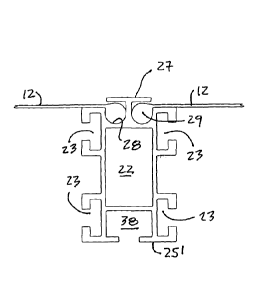
As shown in Figures 4A and 46, the extruded profile straight metal tubes 15
have a
common transverse profile defining interconnection means in the form of
channels such as a
central interconnecting channel 22 and side interconnecting channels 23. It
also defines a
T-shaped projection 24 extending above a top wall 25 thereof. The T-shaped
projection
defines a central wall 26 and a transverse top wall 27. Opposed, generally U-
shaped tarp
connecting channels 28 are formed under the transverse top wall 27 for
receiving the
enlarged connecting side edges 29 of a tarp section 12.
Referring now to Figures 5A and 7 to 10B, there will be described the
construction of
.. the corner connector 16 as better shown in Figures 7 to 9. The corner joint
connector 16 is
comprised of a rigid central body portion 30 having opposed connecting wing
portions 31
integrally formed therewith. The central body portion and the wing connecting
portions have
transversal holes 32 therein for interconnection with profile straight metal
tubes 15 and for
connection with a corner connecting joint plate 33, as illustrated in Figures
10A and 1013.
As can be seen from these drawings, the central body portion 30 and the
opposed wing
portions 31 extending from both ends of the central body portion and define an
interconnecting axis, herein a curved axis 34, which determines the angle
between the
straight metal tubes 15 in the opposed side sections with respect to the
straight metal tubes
15 in the roof section 18. These opposed connecting wing sections 31 are
received in close
sliding fit in the central interconnecting channel 22 of a straight metal tube
15. As shown in
Figure 5A, connecting bolt fasteners 34 secure the wing portions 31 to the end
of the
extruded metal tubes 15. The connecting fastener 35 secures the corner
connecting joint
CA 02884195 2015-03-04
WO 2014/036635
PCT/CA2013/000758
plate 33 to each of the opposed side walls 30' of the rigid central body
portion 30. The
fastener 35 is engaged in the hole 32'. These holes 32 and 32' may be threaded
to receive
the connecting bolt fasteners 34 and 35.
Stub connecting projections 37 of rectangular cross-section extend from the
central
body portion 30 and are spaced under each of the opposed connecting wing
portions 31 and
are dimensioned for close-fit connection in a lower joint interconnecting
channel 38 of the
profile straight metal tube 15, as shown in Figure 4A, whereby to provide
added connection
strength between the connectors and the straight metal tubes.
With reference now to Figures 9, it can be seen that the corner connector 16
is also
provided with a T-shaped projection 24' and it also has a central wall 26' to
define on
opposed sides thereof U shaped channels 28'. This T-shaped projection 24' is
positioned to
align itself with the T shaped projection 24 form on the top wall 25 of the
straight metal tubes
once the corner connector 16 is secured thereto. In order to install the tarp
sections 12
across two of the structural bow frames structures 11, the enlarged opposed
beaded side
15 edges 29 of
the tarp section, see Figure 4B, is inserted into one of the U-shaped channels
28 of the straight metal tube forming the roof section 18 via the larger U-
shaped channel 28'
above the rigid central body portion 30. The tarp enlarged beaded side edge 29
is secured
to a wire or rope which pulls the enlarged beaded side edge 29 through the U-
shaped
channel 28 of the two cross bow frames selected. The selected bow frames may
be
alternate bow frames of bow frames of alternating fourth bow frames with the
intermediate
bow frames being mainly tarp supporting bow frames. After the tarp is pulled
to the bottom
of the opposed side section 19 it is secured to the bottom thereof and the
remaining tarp
section is then inserted into the U-shaped channel 28 of the vertical straight
metal tubes 15"
as illustrated in Figure 5A via the U-shaped channel 28'.
After the tarp section is installed between two bow frames, the corner
connecting
joint plate 33 is secured in position to cause the tarp beaded edge to assume
a smooth
11
CA 02884195 2015-03-04
WO 2014/036635
PCT/CA2013/000758
curve. As shown in Figures 4A and 5A, the U-shaped channels form a restricted
throat
opening 38 through which the tarp 12 extends and prevents foreign matter from
lodging into
the U-shaped channels 28. Likewise, the corner connecting joint plate 33 is
dimensioned to
form an aligned restricted throat opening 38', as shown in Figure 5A.
Figure 5B shows the construction of the peak connector 17 and its construction
is the
same as described for the corner connector 16 except that the shape is
different. It performs
the same function as a corner connector and therefore it will not be described
in detail herein
as its construction is obvious to a person skilled in the art.
Figures 6A, 6B and 11A and 11B illustrate a variant of the corner connector,
herein
corner connector 16' and the peak connector, herein peak connector 17'. In
this variant, the
corner connecting joint plate 33' of the corner connector and the peak
connector has an
extended lower portion 39 and 39', respectively, which is adapted to receive
an attachment
bolt 40 and 40' whereby to secure thereto truss arms 41 or truss cables as
will now be
described, and shown in Figures 17A and 17B. A truss structure is attached
under the pitch
roof section 18 and between the opposed side sections 19 at a top end thereof.
The truss
structure is constituted by MF tubes or tension wire cables or straight flat
metal bars 42
interconnected together between the corner joint plates and peak connecting
joint plates as
shown in Figures 6A and 6B and which also constitutes truss connectors. Truss
connectors
43 are also mounted in the joint interconnecting channel 38 of the profiled
straight metal
tubes 15 constituting the pitch roof section 18. As herein shown, the straight
metal rod 42
extends from across opposed ones of the corner joint connectors 16' and the
truss arms 41
interconnect vertically thereto. A tie cable 44 provide load transfer
connections between the
lower end of the truss arms 41 and the peak joint connector 17' to transfer
the loading of the
roof sections to the opposed side sections 19.
Referring now to Figures 12A to 12C, there will be described the construction
of one
embodiment of the leg support assembly 20. As hereinshown, the leg support
assembly 20
12
CA 02884195 2015-03-04
WO 2014/036635
PCT/CA2013/000758
is comprised by a pair of rectangular metal plates 50 and 50' which are
identical to one
another and which are formed from an extrusion and define opposed profiled
connecting
edges 51 which are of T-shaped cross-section. To each of these plates is
connected at
least one load bearing support wheel 52 which extends from a flat side wall 53
of each of the
pair of rectangular metal plates 50 and 50. An attachment flange 54 extends
transversally
of the flat side wall 53 of each of the plates and is spaced under the load
bearing support
wheel 52 at a predetermined distance. At least one guide wheel, herein two
guide wheels
55, are supported vertically on the flange 54 and spaced away from the flat
side wall 53.
The load bearing support wheel 57 and guide wheels 55 provide a wheel assembly
for
connection to a support track or rail.
As shown more clearly in Figures 12A and 12B, each of the rectangular metal
plates
50 and 50' are interconnected together by a lower interconnecting extruded
channel member
56 which slidingly receives a lower portion of the profiled connecting side
edge 51 of the
opposed plates 50,50' in side end channels thereof. As illustrated in Figure
12B, the
interconnecting extruded channel member 56 has tarp attachment channels 57
extending
therealong and formed like the U-shaped channels 28, as illustrated in Figure
4A, and these
are disposed on an inner side 58 of the plates 50 and 50' behind the load
bearing support
wheel 52. The channel member 56 also provides a clearance on an outer side
thereof, see
Figure 12C, for the support wheel assembly. A lower end section 15" of the
extruded profile
straight metal tubes 15 of the opposed side sections 19 interconnects to the
metal plates 50
and 50' and sits on top of the interconnecting extruded channel member 56 and
with its U-
shaped channels 28 aligned with the U-shaped channels 57 of the
interconnecting channel
member 56.
Referring now to Figures 13A and 136, there is shown the construction of a
support
rail on which the wheel assembly of the leg support assembly 20 is connected
to. The
support rail 60 has an attachment section 61 which is of L-shaped cross-
section for
immovable securement of the support rail on a ground attachment which may be a
concrete
13
CA 02884195 2015-03-04
WO 2014/036635
PCT/CA2013/000758
wall 62 as illustrated in Figure 13A. The support rail 60 also has a wheel
engaging section
63 defining a support wheel cavity 64 having a wheel supporting horizontal
wall 65 for
support displacement of the load bearing support wheel 52 therein, as
illustrated in Figure
13B. Also, the leg plate may have an additional load bearing wheel 52'
positioned to be
supported on top of the attachment section 61. A depending cavity 67 is formed
under the
wheel supporting horizontal wall 65 for receiving the guide wheels 55
displaceably captive
therein. A top horizontal wall 66 extends parallel above the wheel supporting
horizontal wall
65 and is closely spaced to the top edge of the wheel of the load bearing
support wheel
when displaced therein. This top wall 66 also protects the cavity 64 from
foreign matter.
Also, double leg plates 50 can provide support of the bow frame on opposed
sides of a
support 62 where a rail 60 is secured to opposed top sides of the support. If
the rail expands
or retracts due to temperature fluctuation, the bracket 50 will simply slide
slightly on the rail
and the rail will not buckle. Although Fig. 136 shows the rail 60 with the
attachment section
61 upwards, the rail can also be inserted with the attachment section disposed
flat on a
support surface such as a slab and the wheels inverted on the plates 50, as
shown in
Fig. 13C.
Referring to Figure 14, there is shown another embodiment of the load bearing
support wheel assembly. As hereinshown, it is comprised of a load bearing
support wheel
70 having a concave V-shaped cross-section support surface 71 for seated
rolling support
on a convex V-shaped track 72. A wheel support bracket 73 is secured to a
lower side
portion 74 of the extruded profile straight metal tube 15 of the opposed side
sections 19 of
the structural bow frame. The wheel 70 is supported on an axle 75 supported at
both ends
between a lower portion of the straight metal tube 15 and the lower end 73' of
the bracket
73.
As also shown in Figure 18B, the leg support assembly may comprise solely of a
load bearing support wheel 76 secured under a lower end 77 of the extruded
profile straight
metal tube 15 of the opposed side sections 19 of the inverted bow shape frame.
As herein
14
CA 02884195 2015-03-04
WO 2014/036635
PCT/CA2013/000758
shown, the wheel 76 is secured to a fork 78 having a top connecting post, not
shown, but
secured in the central interconnection channel 22 of the extruded straight
metal tube 15.
With reference now to Figures 15A to 15D, there will be described the
construction of
a reinforce structural bow frame. As hereinshown the reinforced bow frame is
comprised of
two profiled straight metal tubes 15 interconnected together side-by-side in
spaced
relationship by spacer connectors 80. These spacer connectors 80 are simply
short sections
of the straight metal tube 15. These straight sections can be slid between
opposed tubes
and spot welded in place by weld joints not shown. The spacer connectors are
interconnected as illustrated by the transverse views of Figures 15B to 15D.
These double
metal tube structures are interconnected at their corners and peak by corner
connectors as
previously described. The spacer connectors 80 are interconnected to the
opposed tubes
by their T-shaped projection 24 projecting above the top wall 25 and their
joint
interconnecting channel 38 at the other end of the spacer connector 80. The
thickness of
the inner wall 25' (see Figure 4A) provides a close fit under the transverse
tarp wall 27 of the
15 T-shaped projection.
Figure 156 is a top cross-section view illustration of the reinforced
structural bow
frame of Figure 15A and secured to a leg support assembly 20 as previously
described.
Figure 15C illustrates a further reinforced structural bow frame wherein two
of the reinforced
frames as shown in Figure 15A are secured in spaced parallel relationship by
the metal plate
50 of the leg support assembly as shown in Figure 12A. A further metal plate
50 is
connected at the opposite ends of the two interconnected straight metal tubes
15. Figure
15D illustrates a still further reinforced structural bow frame wherein there
are three of these
double straight metal tubes interconnected together by metal plates 50.
With reference now to Figures 16, 17A to 17D, there will be described the
construction of lift bow assemblies 82 which are secured to alternate ones of
the structural
bow frame structures and on opposite sides thereof. The lift bow assemblies 82
are each
comprised by a bow-shaped tubular member 83 which is shaped to define a slope
roof section 84 and
opposed support side arm sections 85. The opposed side arm sections 85 are
pivotally connected at a
lower end thereof to a support bracket 86 which is connected to a side channel
15 of the side sections of
the bow frame structure. The slope roof section 84 extends a predetermined
distance above the roof
section of the structural bow frame, as better seen in Figure 17D, when said
opposed side arm sections
extend upright on their support bracket. However, in use the side arms extend
substantially at the same
level as the roof section 18 of the bow frame.
As shown in Figure 17C, the slope roof section 84 of the lift bow assembly 82
is formed in three
sections 88, 88' and 88". The three sections are pivotally interconnected to
support brackets 86 and
intermediate brackets 87. The intermediate brackets 87 are secured to the
truss rod 42 which is attached
to the reinforced tubes 15' by vertical support rods 41.
Referring now to Figures 18A to 18C there will be described the construction
of the pantograph
frame 90 which interconnects adjacent ones of the displaceable structural bow
frame structures. The
pantograph frame comprises a pair of bars or rods 91 and 91' which are
pivotally connected to one
another at a central crossing point by a pivot connection 92. A lower end 93
of each of the pair of rods is
pivotally secured to a stationary support bracket 94 secured in a connection
channel 95 of an extruded
connector member 95 which is profiled to interconnect with the lower end of a
straight metal tube 15 of
the opposed side sections 19 of the bow frame through a central
interconnecting channel 38'. The
support bracket 94 is fastened to extruded connector member 95. The extruded
connector 95 can also
be secured between the metal plates 50 and 50 of the leg support assembly 20
as illustrated in Figure
12A. The upper end of the rods 91 and 92 are pivotally secured to a sliding
support bracket 96 slidingly
retained captive in the joint interconnecting channel 38 of the straight metal
tube 15 of opposed one of the
side sections of the bow frame. It is pointed out that the upper ends of the
rods 91 and 91' may be fixed
and the lower end displaced on
16
CA 2884195 2019-11-07
CA 02884195 2015-03-04
WO 2014/036635
PCT/CA2013/000758
a slide connector. It is pointed out that additional pantograph frames 90 can
be secured
between the bow frame structures if the enclosure is made higher. The
pantograph frames
also give additional strength to the side sections of the bow frames.
Figures 19A and 19B illustrate the connection of the side arm section 85 of
the lift
bow assemblies to the straight metal tubes 15. As shown, the bow attachment
bracket 86 is
immovably secured in a side interconnecting channel 23 of the straight metal
tube 15 on a
pivot connection 99.
As previously described with reference to Figure 1 the retractable enclosure
of the
present invention may be constructed in shell units consisting of a plurality
of bow frames,
particularly when the retractable enclosure is very long whereby to facilitate
the opening and
closing of the structure from end-to-end or to the sides thereof. Shell units
are identified by
reference numeral 105 illustrated in Figure 1 and they are formed by a
plurality of the
displaceable structural bow frames 11.
The shell units 105 each have interconnectable end frames 200, one of which is
illustrated in Figure 20. Each of the opposed end frame 200 and 200' of
adjacent shell units
105 are interconnected together by slide connectors 107 as will be described
later. As can
be seen from Figure 20 each end frame is constructed of two bow frames 11 and
11'
interconnected in spaced-apart relationship by spacer elements 106 at spaced
intervals
between the two bow frames. The spacer elements 106 which are welded across
the bow
frames 11 and 11'.
Referring now to Figures 20 to 23, it can be seen that the slide connectors
107 are in
the form of flat plates which are provided with attachment legs 109 on the
rear face thereof,
and which are displaceably secured in the side interconnecting channels 23 of
the straight
metal tubes of the bow frames 11 and 11'. A guide tether 110, see Figures 22
and 23, in the
form of a wire or cable interconnects all these slide plates together whereby
the slide plates
can all be displaced in unison. The displacement of these plates is actuated
by an actuating
17
CA 02884195 2015-03-04
WO 2014/036635
PCT/CA2013/000758
means in the form of a ratchet 111 of a type well-known in the art. Of course
other types of
tensioners can be used and operated mechanically or electrically. This ratchet
has a locking
mechanism as is well-known in the art. Each of the slide connectors 107 are
identically
formed and define a retracting notch 112 formed therein. The retracting notch
112 define a
.. slope inner edge 114 behind an outer plate projecting finger formation 113
to capture an
engageable element, herein a pin 115, see Figure 21 which is secured to the
opposed one
200' of the two bow frames 200 and 200'. The engagement pin 15 slides on the
slope inner
edge 114 as the slide plate 107 is displaced to draw the pin towards the base
116 of the
retracting notch 112, thus drawing in the adjacent bow frame 200' in tight fit
with the bow
frame 200. In order to provide a better seal between these two interconnected
bow frames
gaskets 117, as shown in Figure 4C, may be secured in the side interconnecting
channels
23 of the straight metal tubes 15 at opposed ends of the two end frames being
brought into
interlocking relationship.
As shown in Figures 22 and 23, it can be seen that the sliding plate 107', see
Figure
20, secured to one of the opposed side sections 19 of the end frame 200 is
secured to
retracting spring means in the form of a pair of springs 120 whereby to
maintain all the
sliding plates 107 in a disengaged position. The spring force of the springs
120 is selected
to pull all of the sliding locking plates in that position via their
interconnection by the tether
wire 110. The sliding plate 107" secured to the opposed one of the opposed
side sections
19, herein side sections 19', see Figure 23, is connected to a ratchet 111
through a belt 121.
This belt is secured at a lower end 122 thereof about a coil 123 of the
ratchet. The coil is
operated by the crank arm 124 to activate the ratchet, and coil the lower end
of the strap 121
thereabout, thereby drawing the sliding plate 107" into a locked position. To
unlock the
plates, the ratchet 111 is provided with a release mechanism which disengages
the ratchet,
and causes the belt 121 to unwind from the coil by the pulling force of the
springs 120. This
type of ratchet is well-known in the art as above mentioned. Also, the tether
wire 110 is
guided by pulleys secured to the corner connectors and peak connectors.
18
CA 02884195 2015-03-04
WO 2014/036635
PCT/CA2013/000758
With reference now to Figures 24 to 29, there will be described the
construction of
the end bow frames 13 and 13' by the retractable enclosure as illustrated in
Figure 1. The
end frames 13 and 13' are constructed like the interconnecting end frames 200
described
with reference to Figure 20 but do not have sliding connectors. Therefore, the
construction
of the end bow frames 13 and 13' will not be repeated. As hereinshown, one or
both end
bow frames 13 and 13' is provided with a brace arm assembly 130. The brace arm
assembly comprises a brace arm 131 pivotally connected at a top end 132 to a
vertical slide
connector 133 which is a flat slide plate 134 having attachment legs 135, see
Figure 27,
which are slidingly secured in interconnection channel 38 of adjacent bow
frames 11 and
11'. The other end 139 of the brace arm 131 has an abutting formation 140 for
abutting
retention against an abutment bracket 141 and specifically against a vertical
abutment wall
142 of the attachment bracket. It is restrained between opposed side walls 143
of that
bracket whereby to wedge the lower end 139 of the brace arm 131 against the
abutment wall
142. The slide plate 134 is connected at a lower end thereof to a strap 144
which is
connected at a lower end, between the opposed bow frames 11 and 11', to a
ratchet of the
type as described in Figure 23. The actuating lever 124' of this ratchet is
illustrated herein
and the ratchet construction is obvious to a person skilled in the art and has
been briefly
described hereinabove with reference to Figure 23. By positioning the brace
arm 131 in the
position as shown in Figure 24 and actuating the ratchet, causes the slide
plate 134 to be
pulled down by the strap 144. This exerts a pushing force against the end bow
frame 13 to
push it towards the end of the enclosure and thereby exerting a pulling force
on all of the
bow frames of the structure thereby applying a tension to the tarp sections
between the
plurality of the displaceable structural bow frames intermediate opposed end
frames 13 and
13'. When the end frames 13 or 13' required to be displaced, the ratchet is
unlocked thereby
releasing the strap 144 and causing the end frames to move slightly inwardly
of the
enclosure to permit the disengagement of the brace arms 131 and permitting the
brace arm
to be positioned at its stored vertical position, as shown in Figure 28, where
the slide plate
19
CA 02884195 2015-03-04
WO 2014/036635
PCT/CA2013/000758
134 has been pulled to an upper position. Retention means 145 is provided to
maintain the
brace arm in this stored position.
Referring to Figures 30 to 32, there is shown a tarp section 12 interconnected
between the extruded metal tubes 15 of alternate opposed side sections 19 of
structural bow
frame structures. This tarp section 12 is formed of wear-resistant flexible
material. The
inner surface 12', inside the retractable enclosure 10, has a wear-resistant
fin skirt 150
secured thereto, as better illustrated in Figures 31 and 32. The fin skirt 150
extends on a
lower end portion of the tarp and is angled towards the support rail, such as
the rail 60
shown in Figure 30, to stop air flow in and out of the retractable enclosure.
The fin skirt 150
extends between adjacent ones of the plurality of displaceable structural bow
frames 11. As
also illustrated in Figure 31, a flexible rod or flat bar or strip 151 is
secured to the inner
surface 12' of the tarp in an envelope 152 and disposed above the fin skirt
150. The rod 151
has a memory bend whereby to push the lower end of the tarp section between
each of the
bow frames 11 outwardly from the enclosure as the bow frames are displaced
closer to one
another. As also seen in these Figures, the lower end of the tarp section 12
is further
provided on the inner surface 12' thereof with a condensation wicking fin 153
constructed of
material capable of absorbing condensation forming on the inner surface of the
tarp and
dripping down and to direct this condensation inwardly of the support rail 60
to prevent water
from freezing on the support rail.
With reference to Figure 33, it can be seen that the extruded profile straight
metal
tubes 15 may be reinforced by inserting a reinforcing insert 160 in closed
sliding fit in at least
sections of the central interconnecting channel 22 of the straight metal tubes
15 to provide
reinforcement. The insert can be constructed of rigid plastic material or
other suitable
material and as hereinshown, the insert is formed from an extrusion. These
extruded profile
straight metal tubes 15 are also extruded from structural aluminum and are of
suitable
gauge.
CA 02884195 2015-03-04
WO 2014/036635
PCT/CA2013/000758
With reference now to Figure 34, there is shown two snow/ice removal devices
155
and 155' secured to carriages 156 displaceably secured to connecting channels,
such as the
U-shaped channels 28 of an intermediate bow frame structures, such as the bow
frame 19'
to which the tarp is not connected. Accordingly, an unattached tarp section
extends over the
intermediate bow frame structure. The snow/ice removal devices can be
displaced back and
forth by a guided tether wire or cable 157 which is trained about pulleys 158.
Opposed
depending end sections 157' of the cable is made accessible adjacent the
opposed side
sections of the structural bow frame structure to permit a person to pull the
tether from
opposed ends whereby to displace the carriages 156 back and forth along the
intermediate
bow frame structure whereby to dislodge ice or packed snow on the tarp section
intermediate their end connections.
It is within the ambit of the present invention to cover any obvious
modifications of
the preferred embodiments described herein. For example, the tarp sections may
be formed
of one or more layers of flexible textile material and that material may have
insulation
properties. Various other attachment mechanisms or articles can be connected
to the
profiled channels of the straight metal tubes to hang storage structures or
tools from the roof
structural metal tubes or the trusses. A suitable electrical wiring can also
be supported by
brackets secured to the opposed side sections of the bow frames or the roof
sections thereof
by attachments and these attachments may also support fixtures. Flexible
heating ducts
may also be supported by brackets attached to these bow frame structures
particularly when
the retractable enclosure is used as a permanent closed enclosure.
21