Note: Descriptions are shown in the official language in which they were submitted.
METHODS AND SYSTEMS FOR PERFORMING A POSTERIOR CAPSULOTOMY
AND FOR LASER EYE SURGERY WITH A PENETRATED CORNEA
CROSS-REFERENCE
100011 This application claims the benefit of U.S. Provisional Application No.
61/698,516.
filed September 7, 2012, and U.S. Provisional Application No. 61/699,204,
filed September
10,2012.
BACKGROUND
100021 Cataract extraction is one of the most commonly performed surgical
procedures in
the world. A cataract is formed by opacification of the crystalline lens or
its envelope - the
lens capsule - of the eye. A cataract obstructs passage of light through the
lens. A cataract
can vary in degree from slight to complete opacity. Early in the development
of an age-
related cataract the power of the lens may be increased, causing near-
sightedness (myopia).
Gradual yellowing and pacification of the lens may reduce the perception of
blue colors as
those wavelengths are absorbed and scattered within the crystalline lens.
Cataract formation
typically progresses slowly resulting in progressive vision loss. Cataracts
arc potentially
blinding if untreated.
100031 A common cataract treatment involves replacing the opaque crystalline
lens with an
artificial intraocular lens (1014 Presently, an estimated 15 million cataract
surgeries per year
are performed worldwide. The cataract treatment market is composed of various
segments
including intraocular lenses for implantation, viscoclastic polymers to
facilitate surgical
maneuvers, and disposable instrumentation including ultrasonic
phacocmulsification tips,
tubing, various knives, and forceps.
100041 Presently, cataract surgery is typically performed wing a technique
termed
phacoemulsification in which an ultrasonic tip with associated irrigation and
aspiration ports
is used to sculpt the relatively hard nucleus of the lens to facilitate its
removal through an
opening made in the lens anterior capsule. The nucleus of the lens is
contained within an
outer membrane of the lens that is referred to as the lens capsule. Access to
the lens nucleus
can be provided by performing an anterior capsulotomy in which an opening is
formed in the
anterior side of the lens capsule. Access to the lens nucleus can also be
provided by
performing a manual continuous curvilinear capsulorhexis (CCC) procedure,
which has been
recently developed. After removal of the lens nucleus, a synthetic foldable
intraocular lens
-1-
CA 2884235 2019-12-20
CA 02884235 2015-03-05
WO 2014/039869 PCT/US2013/058580
(IOL) can be inserted into the remaining lens capsule of the eye through a
small incision.
Typically, the IOL is held in place by the lens anterior capsule. The IOL may
also be held by
the lens posterior capsule, either alone or in unison with the lens anterior
capsule. This latter
configuration is known in the field as a "bag-in-lens" implant.
[0005] One of the most technically challenging and critical steps in the
cataract extraction
procedure is providing access to the lens nucleus. The manual continuous
curvilinear
capsulorhexis (CCC) procedure evolved from an earlier technique termed can-
opener
capsulotomy in which a sharp needle was used to perforate the lens anterior
capsule in a
circular fashion followed by the removal of a circular fragment of lens
anterior capsule
typically in the range of 5-8 mm in diameter. The smaller the capsulotomy, the
more difficult
it is to produce manually. The capsulotomy facilitates the next step of
nuclear sculpting by
phacoemulsification. Due to a variety of complications associated with the
initial can-opener
technique, attempts were made by leading experts in the field to develop a
better technique
for forming an opening in the lens anterior capsule preceding the
emulsification step.
[0006] The desired outcome of the manual continuous curvilinear capsulorhexis
is to
provide a smooth continuous circular opening through which not only the
phacoemulsification of the nucleus can be performed safely and easily, but
also to provide for
easy insertion of the intraocular lens. The resulting opening in the lens
anterior capsule
provides both a clear central access for tool insertion during removal of the
nucleus and for
IOL insertion, a permanent aperture for transmission of the image to the
retina by the patient,
and also support of the IOL inside the remaining capsule that limits the
potential for
dislocation. The resulting reliance on the shape, symmetry, uniformity, and
strength of the
remaining capsule to contain, constrain, position, and maintain the IOL in the
patient's eye
limits the placement accuracy of the IOL, both initially and over time.
Subsequently, a
patient's refractive outcome and resultant visual acuity are less
deterministic and intrinsically
sub-optimal due to the IOL placement uncertainty. This is especially true for
astigmatism
correcting ("tonic") and accommodating ("presbyopic") 10Ls.
[0007] Problems may also develop related to inability of the surgeon to
adequately
visualize the lens capsule due to lack of red reflex, to grasp the lens
capsule with sufficient
security, and to tear a smooth circular opening in the lens capsule of the
appropriate size and
in the correct location without creating radial rips and extensions. Also
present are technical
difficulties related to maintenance of the depth of the anterior chamber after
opening the lens
-2-
CA 02884235 2015-03-05
WO 2014/039869 PCT/US2013/058580
capsule, small pupil size, and/or the absence of a red reflex due to lens
opacity. Some of the
problems with visualization can be minimized through the use of dyes such as
methylene blue
or indocyanine green. Additional complications may also arise in patients with
weak zonules
(typically older patients) and very young children that have very soft and
elastic capsules,
which are very difficult to controllably and reliably rupture and tear.
[0008] The implantation of a "bag-in-lens" IOL typically uses anterior and
posterior
openings in the lens capsule of the same size. Manually creating matching
capsulotomies for
the "bag-in-lens" configuration, however, is particularly difficult.
[0009] Many cataract patients have astigmatic visual errors. Astigmatism can
occur when
the corneal curvature is unequal in all directions. IOLs can be used to
correct for astigmatism
but require precise rotational and central placement. Additionally, 10Ls are
not typically
used for correction beyond 5D of astigmatism. Many patients, however, have
astigmatic
visual errors exceeding 5D. Higher correction beyond 5D typically requires
reshaping the
cornea to make it more spherical. There are numerous existing approaches for
reshaping the
cornea, including Corneaplasty, Astigmatic Keratotomy, Corneal Relaxing
Incision (CRI),
and Limbal Relaxing Incision (LRI). In Astigmatic Keratotomy, Corneal Relaxing
Incision
(CRI), and Limbal Relaxing Incision (LRI), corneal incisions are made in a
well-defined
manner and depth to allow the cornea to change shape to become more spherical.
Presently,
these corneal incisions are typically accomplished manually often with limited
precision.
[0010] Thus, improved methods and systems for treating cataracts are needed.
SUMMARY
[0011] Methods and apparatus for performing a posterior capsulotomy and for
performing
laser eye surgery with a penetrated cornea are disclosed. The disclosed
methods provide for
the formation of precise openings in the anterior and posterior sides of the
lens capsule,
thereby preparing the lens capsule to receive a replacement lens (e.g., a "bag-
in-lens" lens, or
any other suitable lens including an existing IOL). And the disclosed methods
for performing
laser eye surgery with a penetrated cornea can be used, for example, to treat
an eye having a
pupil that does not dilate sufficiently to provide adequate surgical access.
[0012] In one aspect, a method is provided for performing laser-assisted
cataract surgery on
an eye having a lens posterior capsule and an anterior hyaloid membrane. The
method
includes injecting fluid between the lens posterior capsule and the anterior
hyaloid membrane
to separate the lens posterior capsule and the anterior hyaloid membrane. With
the lens
-3-
CA 02884235 2015-03-05
WO 2014/039869 PCT/US2013/058580
posterior capsule separated from the anterior hyaloid membrane, a posterior
capsulotomy is
performed on the lens posterior capsule by using a laser to incise the lens
posterior capsule.
The fluid can be injected into the Berger's space of the eye. In many
embodiments, the fluid
is an ophthalmic viscosurgical device (OVD). In many embodiments, the
posterior
capsulotomy leaves the anterior hyaloid membrane completely intact.
[0013] The posterior capsulotomy can be performed using any suitable
parameters. For
example, the posterior capsulotomy can be performed using an incision depth
between 400
um and 800 ium. In many embodiments, the posterior capsulotomy is performed
using pulse
energy between 7 J and 10 0. In many embodiments, the posterior capsulotomy is
performed using a capsulotomy diameter of at least 3.5 mm.
[0014] The method for performing laser-assisted cataract surgery on an eye
having a lens
posterior capsule and an anterior hyaloid membrane can include one or more
additional acts.
For example, the method can include installing a replacement lens so that the
replacement
lens is at least partially constrained by the lens capsule. For example, the
replacement lens
can be installed using a posterior optic buttonholing technique. As another
example, the
replacement lens can be installed using a bag-in-lens technique. The method
can include
performing an anterior capsulotomy on the lens capsule by using a laser to
incise the lens
capsule. The method can include removing at least a portion of the lens
nucleus.
[0015] In another aspect, a method is provided for performing laser eye
surgery on an eye
having a cornea. The method includes coupling an eye having a penetration
through the
cornea to a laser surgery system by using a liquid interface disposed between
the cornea and
the laser surgery system, and forming one or more incisions in the eye by
using the laser
surgery system to transmit light through the liquid interface.
[0016] The method for performing laser eye surgery on an eye having a cornea
can include
additional acts. For example, the method can include forming the penetration
through the
cornea. The method can include inserting an iris-expanding device through the
penetration in
the cornea.
[0017] In another aspect, a system is provided for performing laser-assisted
cataract
surgery on an eye having an anterior chamber. The system includes a laser
configured to
generate a laser beam comprising a plurality of laser pulses, a scanning
assembly configured
to scan a focal point of the laser beam within the eye to incise eye tissue,
and a controller
configured to scan the focal point to incise eye tissue so as to account for
at least one optical
-4-
CA 02884235 2015-03-05
WO 2014/039869 PCT/US2013/058580
characteristic of an OVD in the anterior chamber to determine one or more
control
parameters used to control scanning of the focal point.
[0018] In many embodiments, the system for performing laser-assisted cataract
surgery on
an eye having an anterior chamber further includes an imaging device
configured to generate
output in response to imaging the eye. In many embodiments, the controller is
configured to
process output from the imaging device to determine dimensional attributes of
the anterior
chamber and use the dimensional attributes of the anterior chamber in
conjunction with an
index of refraction for the OVD disposed in the anterior chamber to operate
the scanning
assembly to scan the focal point to incise eye tissue so as to account for the
at least one
optical characteristic of the OVD.
[0019] In another aspect, a method is provided for performing laser-assisted
cataract
surgery on an eye having an anterior chamber. The method includes generating a
laser beam
comprising a plurality of pulses, and scanning a focal point of the laser beam
within the eye
to incise tissue of the eye disposed posterior to the anterior chamber so as
to account for at
least one optical characteristic of an OVD disposed in the anterior chamber to
determine one
or more control parameters used to control scanning of the focal point. In
many
embodiments, the OVD has an index of refraction and the accounted for at least
one optical
characteristic of the OVD includes the index of refraction.
[0020] In many embodiments, the method includes processing output from an
imaging
device to determine dimensional attributes of the anterior chamber. The
dimensional
attributes of the anterior chamber are used in conjunction with the index of
refraction of the
OVD to operate the scanning assembly to scan the focal point to incise eye
tissue so as to
account for the at least one optical characteristic of the OVD.
[0021] In another aspect, a method is provided for performing a laser-assisted
posterior
capsulotomy on a lens posterior capsule of an eye. The method includes
injecting fluid
between a replacement lens and the lens posterior capsule to separate the lens
posterior
capsule and the replacement lens, and performing a posterior capsulotomy on
the lens
posterior capsule by using a laser to incise the lens posterior capsule. In
many embodiments,
the injected fluid is an OVD.
[0022] The method for perfoHning a laser-assisted posterior capsulotomy on a
lens
posterior capsule of an eye can include one or more additional acts. For
example, the method
can include injecting fluid between the lens posterior capsule and an anterior
hyaloid
-5-
membrane of the eye to separate the lens posterior capsule and the anterior
hyaloid
membrane. In many embodiments, the posterior capsulotomy leaves the anterior
hyaloid
membrane completely intact.
100231 The posterior capsulotomy can be performed using any suitable
parameters. For
example, the posterior capsulotomy can be performed using an incision depth
between 400
trn to 800 gam. The posterior capsulotomy can be performed using pulse energy
between 7
Ili to 10 tt.J. The posterior capsulotomy can be performed using a capsulotomy
diameter of at
least 3.5 mm.
100241 In many embodiments, performing the posterior capsulotomy includes
compensating for the presence of the replacement lens. For example, performing
the
posterior capsulotomy can include using an index of refraction for the
replacement lens to
determine control parameters used to scan the laser to incise the lens
posterior capsule.
100251 In many embodiments, the method for performing a laser-assisted
posterior
capsulotomy on a lens posterior capsule of an eye includes onc or more
additional acts. For
example, the method can include performing an anterior capsulotomy on the tens
capsule by
using a laser to incise the lens capsule, removing at least a portion of the
lens nucleus, and
installing the replacement lens so that the replacement lens is at least
partially constrained by
the lens capsule having the anterior capsulotomy.
100261
BRIEF DESCRIPTION OF THE DRAWINGS
100271 The novel features of the invention are set forth with particularity in
the appended
claims. A better understanding of the features and advantages of the present
invention will be
obtained by reference to the following detailed description that sets forth
illustrative
embodiments, in which the principles of the invention arc utilized, and the
accompanying
drawings of which:
-6-
CA 2884235 2019-12-20
CA 02884235 2015-03-05
WO 2014/039869
PCT/US2013/058580
[0028] FIG. 1 shows a schematic representation of an embodiment of a system
that can be
used to perform a posterior capsulotomy and to perform surgery on an eye
having a
penetrated cornea.
[0029] FIG. 2 shows a schematic representation of aspects of another
embodiment of a
system that can be used to perform a posterior capsulotomy and to perform
surgery on an eye
having a penetrated cornea.
[0030] FIG. 3 shows a schematic representation of another embodiment of a
system that
can be used to perform a posterior capsulotomy and to perform surgery on an
eye having a
penetrated cornea.
[0031] FIG. 4 shows a schematic representation of another embodiment of a
system that
can be used to perform a posterior capsulotomy and to perform surgery on an
eye having a
penetrated cornea.
[0032] FIG. 5 is a cross-sectional diagrammatic view of a lens capsule and an
adjacent
portion of the anterior hyaloid membrane of the vitreous, in accordance with
many
embodiments.
[0033] FIG. 6 is a cross-sectional diagrammatic view showing the lens
posterior capsule
inverted and displaced relative to the anterior hyaloid surface of the
vitreous and a closed
boundary incision surface transecting the lens posterior capsule, in
accordance with many
embodiments.
[0034] FIG. 7 is a cross-sectional diagrammatic view of an implanted bag-in-
lens 10L, in
accordance with many embodiments.
[0035] FIG. 8 is a side view diagram of an IOL positioned in a lens capsule
and an
adjacent portion of the anterior hyaloid membrane of the vitreous displaced
relative to the
lens posterior capsule, in accordance with many embodiments.
[0036] FIG. 9 is a side view diagram showing the lens posterior capsule
displaced relative
to the IOL of FIG. 8 and a closed boundary incision surface transecting the
lens posterior
capsule, in accordance with many embodiments.
[0037] FIG. 10 is a simplified block diagram of acts of a method for
installing an iris-
expanding device, in accordance with many embodiments.
[0038] FIG. 11 is a cross-sectional diagrammatic view of an anterior chamber
of an eye
that contains an ophthalmic visco surgical device (OVD) and how the refractive
index of the
-7-
CA 02884235 2015-03-05
WO 2014/039869 PCT/US2013/058580
OVD can impact the targeting of a laser beam transmitted through the OVD, in
accordance
with many embodiments.
[0039] FIG. 12 shows a cross-sectional view image of an eye obtained via OCT
imaging,
in accordance with many embodiments.
[0040] FIG. 13 is a simplified block diagram of acts of a method of performing
laser eye
surgery on an eye having one or more corneal penetrations, in accordance with
many
embodiments.
[0041] FIG. 14A and FIG. 14B are simplified diagrammatic views of flat and
curved
applanation interfaces, respectively, coupled to an eye.
[0042] FIG. 14C is a simplified diagrammatic view of a liquid optical
interface, in
accordance with many embodiments, coupled to an eye.
[0043] FIG. 15 is a chart presenting observed intraocular pressures before,
during, and
after surgery on eyes using an embodiment of a liquid optical interface.
DETAILED DESCRIPTION
[0044] The present invention can be implemented by a system that projects or
scans an
optical beam into a patient's eye 68, such as system 2 shown in FIG. 1. System
2 includes an
ultrafast (UF) light source 4 (e.g., a femtosecond laser). Using system 2, a
beam can be
scanned in the patient's eye 68 in three dimensions: X, Y, Z. Short-pulsed
laser light can be
focused into eye tissue to produce dielectric breakdown to cause
photodisruption around the
focal point (the focal zone), thereby rupturing the tissue in the vicinity of
the photo-induced
plasma. In this embodiment, the wavelength of the laser light can vary between
800nm to
1200nm and the pulse width of the laser light can vary from 10fs to 10000fs.
The pulse
repetition frequency can also vary from 10 kHz to 500 kHz. Safety limits with
regard to
unintended damage to non-targeted tissue bound the upper limit with regard to
repetition rate
and pulse energy. Threshold energy, time to complete the procedure, and
stability bound the
lower limit for pulse energy and repetition rate. The peak power of the
focused spot in the
eye 68 and specifically within the crystalline lens 69 and lens anterior
capsule of the eye is
sufficient to produce optical breakdown and initiate a plasma-mediated
ablation process.
Near-infrared wavelengths are preferred because linear optical absorption and
scattering in
biological tissue is reduced for near-infrared wavelengths. As an example,
laser 4 can be a
repetitively pulsed 1035 nm device that produces 500 fs pulses at a repetition
rate of 100 kHz
and individual pulse energy in a suitable range (e.g., from 7 to 10
microjoule).
-8-
CA 02884235 2015-03-05
WO 2014/039869 PCT/US2013/058580
[0045] The laser 4 is controlled by control electronics 300, via an input and
output device
302, to create optical beam 6. Control electronics 300 may be a computer,
microcontroller,
etc. In this example, the controller 300 controls the entire system and data
is moved through
input/output device TO 302. A graphical user interface GUI 304 can be used to
set system
operating parameters, process user input (UI) 306, and display gathered
information such as
images of ocular structures.
[0046] The generated UF light beam 6 proceeds towards the patient eye 68
passing through
a half-wave plate 8 and a linear polarizer, 10. The polarization state of the
beam can be
adjusted so that the desired amount of light passes through the half-wave
plate 8 and the
linear polarizer 10, which together act as a variable attenuator for the UF
beam 6.
Additionally, the orientation of the linear polarizer 10 determines the
incident polarization
state incident upon a beam combiner 34, thereby optimizing the beam combiner
34
throughput.
[0047] The UF light beam 6 proceeds through a system-controlled shutter 12, an
aperture
14, and a pickoff device 16. The system-controlled shutter 12 ensures on/off
control of the
laser for procedural and safety reasons. The aperture 14 sets an outer useful
diameter for the
UF light beam 6 and the pickoff device 16 monitors the resulting beam. The
pickoff device
16 includes a partially reflecting mirror 20 and a detector 18. Pulse energy,
average power,
or a combination can be measured using the detector 18. Output from the
detector 18 can be
used for feedback to the half-wave plate 8 for attenuation and to verify
whether the system-
controlled shutter 12 is open or closed. In addition, the system-controlled
shutter 12 can have
position sensors to provide a redundant state detection.
[0048] The beam passes through a beam conditioning stage 22, in which beam
parameters
such as beam diameter, divergence, circularity, and astigmatism can be
modified. In this
illustrative example, the beam conditioning stage 22 includes a two-element
beam expanding
telescope comprised of spherical optics 24, 26 in order to achieve the
intended beam size and
collimation. Although not illustrated here, an anamorphic or other optical
system can be used
to achieve the desired beam parameters. The factors used to determine these
beam
parameters include the output beam parameters of the laser, the overall
magnification of the
system, and the desired numerical aperture (NA) at the treatment location. In
addition, the
beam conditioning stage 22 can be used to image aperture 14 to a desired
location (e.g., the
center location between a 2-axis scanning device 50 described below). In this
way, the
-9-
CA 02884235 2015-03-05
WO 2014/039869 PCT/US2013/058580
amount of light that makes it through the aperture 14 is assured to make it
through the
scanning system. The pickoff device 16 is then a reliable measure of the
usable light.
[0049] After exiting the beam conditioning stage 22, the beam 6 reflects off
of fold
mirrors 28, 30, 32. These mirrors can be adjustable for alignment purposes.
The beam 6 is
then incident upon the beam combiner 34. The beam combiner 34 reflects the UF
beam 6
(and transmits both the imaging, in this exemplary case, an optical coherence
tomography
(OCT) beam 114, and an aim 202 beam described below). For efficient beam
combiner
operation, the angle of incidence is preferably kept below 45 degrees and the
polarization of
the beams is fixed where possible. For the UF beam 6, the orientation of the
linear polarizer
provides fixed polarization. Although OCT is used as the imaging modality in
this non¨
limiting example, other approaches, such as Purkinje imaging, Schcimpflug
imaging,
confocal or nonlinear optical microscopy, fluorescence imaging, ultrasound,
structured light,
stereo imaging, or other known ophthalmic or medical imaging modalities and/or
combinations thereof may be employed.
[0050] Following the beam combiner 34, the beam 6 continues onto a z-adjust or
Z scan
device 40. In this illustrative example the z-adjust 40 includes a Galilean
telescope with two
lens groups 42, 44 (each lens group includes one or more lenses). The lens
group 42 moves
along the z-axis about the collimation position of the telescope. In this way,
the focus
position of the spot in the patient's eye 68 moves along the z-axis as
indicated. In general,
there is a fixed linear relationship between the motion of lens 42 and the
motion of the focus.
In this case, the z-adjust telescope has an approximate 2x beam expansion
ratio and a 1:1
relationship of the movement of lens 42 to the movement of the focus.
Alternatively, the lens
group 44 could be moved along the z-axis to actuate the z-adjust, and scan.
The z-adjust 40
is the z-scan device for treatment in the eye 68. It can be controlled
automatically and
dynamically by the system and selected to be independent or to interplay with
the X-Y scan
device described next. The mirrors 36, 38 can be used for aligning the optical
axis with the
axis of the z-adjust device 40.
[0051] After passing through the z-adjust device 40, the beam 6 is directed to
the x-y scan
device 50 by mirrors 46, 48. The mirrors 46, 48 can be adjustable for
alignment purposes.
X-Y scanning is achieved by the scanning device 50 preferably using two
mirrors 52, 54
under the control of the control electronics 300, which rotate in orthogonal
directions using
motors, galvanometers, or any other well known optic moving device. The
mirrors 52, 54 are
-10-
CA 02884235 2015-03-05
WO 2014/039869 PCT/US2013/058580
located near the telecentric position of an objective lens 58 and a liquid
optical interface 66
combination described below. Tilting the minors 52, 54 changes the resulting
direction of
the beam 6, causing lateral displacements in the plane of UF focus located in
the patient's eye
68. The objective lens 58 may be a complex multi-element lens element, as
shown, and
represented by lenses 60, 62, and 64. The complexity of the objective lens 58
will be
dictated by the scan field size, the focused spot size, the available working
distance on both
the proximal and distal sides of objective lens 58, as well as the amount of
aberration control.
An f-theta objective lens 58 of focal length 60mm generating a spot size of
101um, over a
field of lOmm, with an input beam size of 15mm diameter is an example.
Alternatively, X-Y
scanning by the scanning device 50 may be achieved by using one or more
moveable optical
elements (e.g., lenses, gratings), which also may be controlled by the control
electronics 300,
via the input and output device 302.
[0052] The scanning device 50 under the control of the control electronics 300
can
automatically generate the aiming and treatment scan patterns. Such patterns
may be
comprised of a single spot of light, multiple spots of light, a continuous
pattern of light,
multiple continuous patterns of light, and/or any combination of these. In
addition, the
aiming pattern (using the aim beam 202 described below) need not be identical
to the
treatment pattern (using the light beam 6), but preferably at least defines
its boundaries in
order to assure that the treatment light is delivered only within the desired
target area for
patient safety. This may be done, for example, by having the aiming pattern
provide an
outline of the intended treatment pattern. This way the spatial extent of the
treatment pattern
may be made known to the user, if not the exact locations of the individual
spots themselves,
and the scanning thus optimized for speed, efficiency and accuracy. The aiming
pattern may
also be made to be perceived as blinking in order to further enhance its
visibility to the user.
[0053] The liquid optical interface 66, which can include any suitable
ophthalmic lens, can
be used to help further focus the light beam 6 into the patient's eye 68 while
helping to
stabilize eye position. The positioning and character of the light beam 6
and/or the scan
pattern the light beam 6 forms on the eye 68 may be further controlled by use
of an input
device such as a joystick, or any other appropriate user input device (e.g.,
GUI 304) to
position the patient and/or the optical system.
[0054] The UF laser 4 and the control electronics 300 can be set to target the
targeted
structures in the eye 68 and ensure that the light beam 6 will be focused
where appropriate
-11-
CA 02884235 2015-03-05
WO 2014/039869 PCT/US2013/058580
and not unintentionally damage non-targeted tissue. Imaging modalities and
techniques
described herein, such as those mentioned above, or ultrasound may be used to
determine the
location and measure the thickness of the lens and lens capsule to provide
greater precision to
the laser focusing methods, including 2D and 3D patterning. Laser focusing may
also be
accomplished using one or more methods including direct observation of an
aiming beam, or
other known ophthalmic or medical imaging modalities, such as those mentioned
above,
and/or combinations thereof In the embodiment of FIG. 1, an OCT device 100 is
described,
although other modalities are within the scope of the present invention. An
OCT scan of the
eye will provide information about the axial location of the lens anterior and
posterior
capsule, the boundaries of the cataract nucleus, as well as the depth of the
anterior chamber.
This information is then loaded into the control electronics 300, and used to
program and
control the subsequent laser-assisted surgical procedure. The information may
also be used
to determine a wide variety of parameters related to the procedure such as,
for example, the
upper and lower axial limits of the focal planes used for cutting the lens
capsule and
segmentation of the lens cortex and nucleus, and the thickness of the lens
capsule among
others.
[00551 The OCT device 100 in FIG. 1 includes a broadband or a swept light
source 102
that is split by a fiber coupler 104 into a reference arm 106 and a sample arm
110. The
reference arm 106 includes a module 108 containing a reference reflection
along with
suitable dispersion and path length compensation. The sample arm 110 of the
OCT device
100 has an output connector 112 that serves as an interface to the rest of the
UF laser system.
The return signals from both the reference and sample arms 106, 110 are then
directed by
coupler 104 to a detection device 128, which employs a time domain detection
technique, a
frequency detection technique, or a single point detection technique. In FIG.
1, a frequency
domain technique is used with an OCT wavelength of 920nm and bandwidth of
100nm.
[0056] After exiting the connector 112, the OCT beam 114 is collimated using a
lens 116.
The size of the collimated OCT beam 114 is determined by the focal length of
the lens 116.
The size of the beam 114 is dictated by the desired NA at the focus in the eye
and the
magnification of the beam train leading to the eye 68. Generally, the OCT beam
114 does
not require as high an NA as the UF light beam 6 in the focal plane and
therefore the OCT
beam 114 is smaller in diameter than the UF light beam 6 at the beam combiner
34 location.
Following the collimating lens 116 is an aperture 118, which further modifies
the resultant
-12-
CA 02884235 2015-03-05
WO 2014/039869 PCT/US2013/058580
NA of the OCT beam 114 at the eye. The diameter of the aperture 118 is chosen
to optimize
OCT light incident on the target tissue and the strength of the return signal.
A polarization
control element 120, which may be active or dynamic, is used to compensate for
polarization
state changes. The polarization state changes may be induced, for example, by
individual
differences in corneal birefringence. 122, 124 are then used to direct the OCT
beam 114
towards beam combiners 126, 34. Mirrors 122, 124 can be adjustable for
alignment purposes
and in particular for overlaying of the OCT beam 114 to the UF light beam 6
subsequent to
the beam combiner 34. Similarly, the beam combiner 126 is used to combine the
OCT beam
114 with the aim beam 202 as described below.
[0057] Once combined with the UF light beam 6 subsequent to beam combiner 34,
the
OCT beam 114 follows the same path as the UF light beam 6 through the rest of
the system.
In this way, the OCT beam 114 is indicative of the location of the UF light
beam 6. The OCT
beam 114 passes through the z-scan 40 and x-y scan 50 devices then the
objective lens 58, the
liquid optical interface 66, and on into the eye 68. Reflections and scatter
off of structures
within the eye provide return beams that retrace back through the optical
system, into the
connector 112, through the coupler 104, and to the OCT detector 128. These
return back
reflections provide OCT signals that are in turn interpreted by the system as
to the location in
X, Y, and Z of UF light beam 6 focal location.
[0058] The OCT device 100 works on the principle of measuring differences in
optical path
length between its reference and sample arms. Therefore, passing the OCT beam
114
through the z-adjust device 40 does not extend the z-range of the OCT system
100 because
the optical path length does not change as a function of movement of the lens
group 42. The
OCT system 100 has an inherent z-range that is related to the detection
scheme, and in the
case of frequency domain detection it is specifically related to the
spectrometer and the
location of the reference arm 106. In the case of OCT system 100 used in FIG.
1, the z-range
is approximately 1-2mm in an aqueous environment. Extending this range to at
least 4mm
involves the adjustment of the path length of the reference arm within OCT
system 100.
Passing the OCT beam 114 in the sample arm through the z-scan of z-adjust
device 40 allows
for optimization of the OCT signal strength. This is accomplished by focusing
the OCT
beam 114 onto the targeted structure while accommodating the extended optical
path length
by commensurately increasing the path within the reference arm 106 of OCT
system 100.
-13-
CA 02884235 2015-03-05
WO 2014/039869 PCT/US2013/058580
[0059] Because of the fundamental differences in the OCT measurement with
respect to the
UF focus device due to influences such as immersion index, refraction, and
aberration, both
chromatic and monochromatic, care must be taken in analyzing the OCT signal
with respect
to the UF beam focal location. A calibration or registration procedure as a
function of X, Y,
and Z should be conducted in order to match the OCT signal information to the
UF focus
location and also to the relative to absolute dimensional quantities.
[0060] Observation of an aim beam may also be used to assist the user to
directing the UF
laser focus. Additionally, an aim beam visible to the unaided eye in lieu of
the infrared OCT
beam and the UF light beam can be helpful with alignment provided the aim beam
accurately
represents the infrared beam parameters. An aim subsystem 200 is employed in
the
configuration shown in FIG. 1. The aim beam 202 is generated by an aim beam
light
source 201, such as a helium-neon laser operating at a wavelength of 633nm.
Alternatively a
laser diode in the 630-650nm range can be used. An advantage of using the
helium neon
633nm beam is its long coherence length, which would enable the use of the aim
path as a
laser unequal path-length interferometer (LUPI) to measure the optical quality
of the beam
train, for example.
[0061] Once the aim beam light source 201 generates the aim beam 202, the aim
beam 202
is collimated using a lens 204. The size of the collimated beam is determined
by the focal
length of the lens 204. The size of the aim beam 202 is dictated by the
desired NA at the
focus in the eye and the magnification of the beam train leading to the eye
68. Generally, the
aim beam 202 should have close to the same NA as the UF light beam 6 in the
focal plane
and therefore the aim beam 202 is of similar diameter to the UF light beam 6
at the beam
combiner 34. Because the aim beam 202 is meant to stand-in for the UF light
beam 6 during
system alignment to the target tissue of the eye, much of the aim path mimics
the UF path as
described previously. The aim beam 202 proceeds through a half-wave plate 206
and a linear
polarizer 208. The polarization state of the aim beam 202 can be adjusted so
that the desired
amount of light passes through the polarizer 208. The half-wave plate 206 and
the linear
polarizer 208 therefore act as a variable attenuator for the aim beam 202.
Additionally, the
orientation of polarizer 208 determines the incident polarization state
incident upon the beam
combiners 126, 34, thereby fixing the polarization state and allowing for
optimization of the
throughput of the beam combiners 126, 34. Of course, if a semiconductor laser
is used as the
aim beam light source 200, the drive current can be varied to adjust the
optical power.
-14-
CA 02884235 2015-03-05
WO 2014/039869 PCT/US2013/058580
[0062] The aim beam 202 proceeds through a system-controlled shutter 210 and
an
aperture 212. The system-controlled shutter 210 provides on/off control of the
aim beam
202. The aperture 212 sets an outer useful diameter for the aim beam 202 and
can be
adjusted appropriately. A calibration procedure measuring the output of the
aim beam 202 at
the eye can be used to set the attenuation of aim beam 202 via control of the
polarizer 206.
[0063] The aim beam 202 next passes through a beam-conditioning device 214.
Beam
parameters such as beam diameter, divergence, circularity, and astigmatism can
be modified
using one or more well known beaming conditioning optical elements. In the
case of the aim
beam 202 emerging from an optical fiber, the beam-conditioning device 214 can
simply
include a beam-expanding telescope with two optical elements 216, 218 in order
to achieve
the intended beam size and collimation. The final factors used to determine
the aim beam
parameters such as degree of collimation are dictated by what is necessary to
match the UF
light beam 6 and the aim beam 202 at the location of the eye 68. Chromatic
differences can
be taken into account by appropriate adjustments of the beam conditioning
device 214. In
addition, the optical system 214 is used to image aperture 212 to a desired
location such as a
conjugate location of the aperture 14.
[0064] The aim beam 202 next reflects off of fold mirrors 220, 222, which are
preferably
adjustable for alignment registration to the UF light beam 6 subsequent to the
beam combiner
34. The aim beam 202 is then incident upon the beam combiner 126 where the aim
beam 202
is combined with the OCT beam 114. The beam combiner 126 reflects the aim beam
202 and
transmits the OCT beam 114, which allows for efficient operation of the beam
combining
functions at both wavelength ranges. Alternatively, the transmit function and
the reflect
function of the beam combiner 126 can be reversed and the configuration
inverted.
Subsequent to the beam combiner 126, the aim beam 202 along with the OCT beam
114 is
combined with the UF light beam 6 by the beam combiner 34.
[0065] A device for imaging the target tissue on or within the eye 68 is shown
schematically in FIG. 1 as an imaging system 71. The imaging system 71
includes a camera
74 and an illumination light source 86 for creating an image of the target
tissue. The imaging
system 71 gathers images that may be used by the control electronics 300 for
providing
pattern centering about or within a predefined structure. The illumination
light source 86 is
generally broadband and incoherent. For example, the light source 86 can
include multiple
LEDs as shown. The wavelength of the illumination light source 86 is
preferably in the range
-15-
CA 02884235 2015-03-05
WO 2014/039869 PCT/US2013/058580
of 700nm to 750nm, but can be anything that is accommodated by a beam combiner
56,
which combines the viewing light with the beam path for the UF light beam 6
and the aim
beam 202 (beam combiner 56 reflects the viewing wavelengths while transmitting
the OCT
and UF wavelengths). The beam combiner 56 may partially transmit the aim
wavelength so
that the aim beam 202 can be visible to the viewing camera 74. An optional
polarization
element 84 in front of the light source 86 can be a linear polarizer, a
quarter wave plate, a
half-wave plate or any combination, and is used to optimize signal. A false
color image as
generated by the near infrared wavelength is acceptable.
[0066] The illumination light from the light source 86 is directed down
towards the eye
using the same objective lens 58 and the liquid optical interface 66 as the UF
light beam 6
and the aim beam 202. The light reflected and scattered off of various
structures in the eye
68 are collected by the same lenses 58, 66 and directed back towards the beam
combiner 56.
At the beam combiner 56, the return light is directed back into the viewing
path via beam
combiner 56 and a mirror 82, and on to the viewing camera 74. The viewing
camera 74 can
be, for example but not limited to, any silicon based detector array of the
appropriately sized
format. A video lens 76 forms an image onto the camera's detector array while
optical
elements 80, 78 provide polarization control and wavelength filtering
respectively. An
aperture or iris 81 provides control of imaging NA and therefore depth of
focus and depth of
field. A small aperture provides the advantage of large depth of field that
aids in the patient
docking procedure. Alternatively, the illumination and camera paths can be
switched.
Furthermore, the aim light source 200 can be made to emit infrared light that
would not be
directly visible, but could be captured and displayed using the imaging system
71.
[0067] Coarse adjust registration is usually needed so that when the liquid
optical interface
66 is coupled with the eye 68, the targeted structures are in the capture
range of the X, Y scan
of the system. Therefore a docking procedure is preferred, which preferably
takes in account
patient motion as the system approaches the contact condition (i.e. contact
between the
patient's eye 68 and the liquid optical interface 66). The viewing system 71
is configured so
that the depth of focus is large enough such that the patient's eye 68 and
other salient features
may be seen before the liquid optical interface 66 makes contact with the eye
68.
[0068] Preferably, a motion control system 70 is integrated into the overall
system 2, and
may move the patient, the system 2 or elements thereof, or both, to achieve
accurate and
reliable contact between the liquid optical interface 66 and the eye 68.
Furthermore, a
-16-
vacuum suction subsystem and flange may be incorporated into the system 2, and
used to
stabilize the eye 68. Alignment of the eye 68 to the system 2 via the liquid
optical interface
66 can be accomplished while monitoring the output of the imaging system 71,
and
performed manually or automatically by analyzing the images produced by the
imaging
system 71 electronically by means of the control electronics 300 via the 10
302. Force and/or
pressure sensor feedback can also be used to discern contact, as well as to
initiate the vacuum
subsystem. An alternate patient interface can also be used, such as that
described in U.S. Pat.
Application No. 13/225,373.
100691 An alternative beam combining configuration is shown in the alternate
embodiment
of FIG. 2. For example, the passive beam combiner 34 in FIG. 1 can be replaced
with an
active combiner 140 as shown in FIG. 2. The active beam combiner 140 can be a
moving or
dynamically controlled element such as a galvanometric scanning mirror, as
shown. The
active combiner 140 changes its angular orientation in order to direct either
the UF light
beam 6 or the combined aim and OCT beams 202,114 towards the scanner 50 and
eventually
towards the eye 68 one at a time. The advantage of the active combining
technique is that it
avoids the difficulty of combining beams with similar wavelength ranges or
polarization
states using a passive beam combiner. This ability is traded off against the
ability to have
simultaneous beams in time and potentially less accuracy and precision due to
positional
tolerances of active beam combiner 140.
100701 Another alternate embodiment is shown in FIG. 3 and is similar to that
of FIG. I
but utilizes an alternate approach to the OCT 100. In FIG. 3, an OCT 101 is
the same as the
OCT 100 in FIG. 1, except that the reference arm 106 has been replaced by a
reference
arm 132. This free-space OCT reference arm 132 is realized by including a beam
splitter 130
after the lens 116. The reference beam 132 then proceeds through a
polarization controlling
element 134 and then onto a reference return module 136. The reference return
module 136
contains the appropriate dispersion and path length adjusting and compensating
elements and
generates an appropriate reference signal for interference with the sample
signal. The sample
arm of OCT 101 now originates subsequent to the beam splitter 130. Potential
advantages of
this free space configunttion include separate polarization control and
maintenance of the
reference and sample arms. The fiber based beam splitter 104 of the OCT 101
can also be
replaced by a fiber based circulator. Alternately, both the OCT detector 128
and the beam
splitter 130 might be moved together as opposed to the reference return module
136.
-17-
CA 2884235 2019-12-20
100711 FIG. 4 shows another alternative embodiment for combining the OCT beam
114
and the UF light beam 6. In FIG. 4, an OCT 156 (which can include either of
the
configurations of OCT 100 or 101) is configured such that an OCT beam 154
output by the
OCT 156 is coupled to the UF light beam 6 after the z-scan device 40 using a
beam combiner
152. In this way, the OCT beam 154 avoids using the z-scan device 40. This
allows the OCT
156 to possibly be folded into the beam more easily and shortening the path
length for more
stable operation. This OCT configuration is at the expense of an optimized
signal return
strength as discussed with respect to FIG. I. There arc many possibilities for
the
configuration of the OCT interferometer, including time and frequency domain
approaches,
single and dual beam methods, swept source, etc, as described in U.S. Pat.
Nos. 5,748,898;
5,748,352; 5,459,570; 6,111,645; and 6,053,613.
100721 The system 2 can be set to locate the surface of the lens capsule and
ensure that the
light beam 6 will be focused on the lens capsule at all points of the desired
opening. Imaging
modalities and techniques described herein, such as for example, Optical
Coherence
Tomography (OCT), such as Purkinje imaging, Schcimpflug imaging, confocal or
nonlinear
optical microscopy, fluorescence imaging, ultrasound, structured light, stereo
imaging, or
other known ophthalmic or medical imaging modalities and/or combinations
thereof may be
used to determine the shape, geometry, perimeter, boundaries, and/or 3-
dimensional location
of the lens and lens capsule to provide greater precision to the laser
focusing methods,
including 2D and 3D patterning. Laser focusing may also be accomplished using
one or
more methods including direct observation of an aiming beam, or other known
ophthalmic or
medical imaging modalities and combinations thereof, such as but not limited
to those
defined above.
100731 Optical imaging of the anterior chamber and lens can be performed on
the lens
using the same laser and/or the same scanner used to produce the patterns for
cutting. This
scan will provide information about the axial location and shape (and even
thickness) of the
lens anterior and posterior capsule, the boundaries of the cataract nucleus,
as well as the
depth of the anterior chamber. This information may then be loaded into the
laser 3-D
scanning system or used to generate a three dimensional
model/representation/image of the
anterior chamber and lens of the eye, and used to define the patterns used in
the surgical
procedure.
-18-
CA 2884235 2019-12-20
CA 02884235 2015-03-05
WO 2014/039869 PCT/US2013/058580
[0074] Posterior Capsulotomy
[0075] In some instances, pacification of the lens posterior capsule occurs
subsequent to
the installation of an intraocular lens (IOL) in place of the natural lens.
Posterior
capsulotomy can be used to prevent vision degradation due lens posterior
capsule
pacification by removing the optically central portion of the lens posterior
capsule, but is
currently limited in application owing to the high level of difficulty
involved in manual
posterior capsulorhexis.
[0076] In many embodiments, the system 2 is configured to perform a posterior
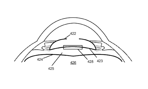
capsulotomy prior to IOL implantation. FIG. 5 illustrates an eye following
anterior
capsulotomy and lens removal. The lens posterior capsule surface of the empty
lens capsule
422 is adjacent to a portion of the anterior hyaloid membrane 424 anterior to
the vitreous 426.
To avoid damage to the anterior hyaloid membrane 424 so as to avoid
potentially
compromising containment of the vitreous 426, the anterior hyaloid membrane
424 can be
separated and displaced relative to the lens posterior capsule 423 using any
suitable approach.
For example, a suitable device (e.g. a 27 gauge self-bent needle 427) can be
guided in a
direction parallel to the lens posterior capsule surface 423 to create a small
opening without
touching the anterior hyaloid surface 424. A small amount of suitable fluid,
such as an OVD,
can be injected through this puncture into the Berger's space 425 behind the
lens posterior
capsule 423 and forward of the anterior hyaloid membrane 424, so as to elevate
and separate
the lens posterior capsule 423 relative to the anterior hyaloid membrane 424.
FIG. 6
illustrates the lens posterior capsule 423 inverted in the anterior direction
following injection
of an OVD into the Berger's space 425.
[0077] An automatic 3D spectral domain OCT can then be performed as described
herein
to generate image data that can be processed by the system 2 to accurately
measure the spatial
disposition of the inverted lens posterior capsule and to characterize the
size, shape, and
dimensions of the corresponding anterior chamber. Such intra-operative OCT
visualization
can be accomplished just prior to and/or during laser incising of the inverted
lens posterior
capsule so as to accurately account for the spatial disposition of the
inverted lens posterior
capsule and/or the configuration of the anterior chamber as it exists during
the incising of the
inverted lens posterior capsule to accomplish the posterior capsulotomy.
[0078] The closed boundary incision surface 428 can be formed using any
suitable system
or method, including those described herein such as the system 2. For example,
the closed
-19-
CA 02884235 2015-03-05
WO 2014/039869 PCT/US2013/058580
boundary incision surface 428 can be formed using concurrent imaging as
described herein to
accurately locate the lens posterior capsule 423 as displaced from the
anterior hyaloid
membrane 424, so as to reduce the extent by which the closed boundary incision
surface 428
extends on one or both sides of the lens posterior capsule 423 to reduce the
probability of
damaging the anterior hyaloid membrane. In many embodiments, system 2 is
configured to
generate surface definitions corresponding to intra-ocular tissue surfaces
(e.g., lens anterior
capsule, lens posterior capsule, corneal anterior surface, corneal posterior
surface). The
generated surface definitions can be depicted in conjunction with displayed
OCT generated
images of the intra-ocular tissues. For example, a cross-sectional display of
an OCT
generated image of intra-ocular tissues can be displayed with overlaid curves
corresponding
to the cross-section of the generated surface definitions for the anterior and
posterior portions
of the lens capsule. In many embodiments, the generated surfaces displayed on
the OCT
images can be adjusted by the system 2 so that the capsulotomy incision is
positioned on the
lens posterior capsule 423. The system 2 can be configured to set a suitable
incision depth
(e.g., 400 to 800 lam), a suitable pulse energy (e.g., 7 to 10 0), and a
suitable capsulotomy
diameter (e.g., at least 3.5 mm). After confirmation of the treatment zones,
the laser
application can be started. A suitable device, such as a micro forceps, can
then be used to
remove the lens posterior capsule disc without touching the intact anterior
hyaloid surface.
[0079] The system 2 can also be used to perform a posterior capsulotomy before
JUL
implantation (no JUL in) without perforating the posterior capsulotomy with a
needle. Such
an approach can be used if there is a circumscript posterior capsular tear to
prevent extension
of the tear by performing a posterior capsulotomy without bringing the lens
posterior capsule
up into a convex shape. Such an approach can be used with an intact anterior
hyaloid
membrane as well as in case of vitreous prolapse.
[0080] An JUL can then be installed by any suitable method. For instance, in
accordance
with a posterior optic buttonholing technique, an open-loop JUL can be
implanted into the
capsular bag. The optic can be buttoned-in by pressing down on the optic such
that lens
posterior capsule is anterior to the JUL and wraps around the periphery of the
JUL optic
between the haptic junctions. Alternatively, in accordance with a bag-in-the-
lens technique, a
suitable JUL (e.g., a BIL 89 A JUL) can be implanted such that the lens
anterior capsule and
the lens posterior capsule are placed in the flanks of the JUL optic. FIG. 7
is a cross-
sectional view illustrating an implanted bag-in-lens JUL 430. The bag-in-lens
JUL 430 has
-20-
CA 02884235 2015-03-05
WO 2014/039869 PCT/US2013/058580
anterior flange 432 and a posterior flange 434 that extend around the
perimeter of the JUL
430 thereby forming a retention groove 436 there between. The retention groove
436
accommodates the lens anterior capsule 438 having an anterior capsulotomy
therein and the
lens posterior capsule 440 having a posterior capsulotomy therein.
[0081] Posterior Capsulotomy with In-situ JUL
[0082] Existing treatment of lens posterior capsule opacification subsequent
to the
installation of an JUL includes removal of the JUL to facilitate access to
performing a
posterior capsulotomy to remove a suitable portion of the opacified lens
posterior capsule so
as to provide a sufficiently sized optical pathway through the lens posterior
capsule. In many
embodiments, the system 2 is configured to perform a posterior capsulotomy
through an IOL,
thereby avoiding removal of the JUL. For example, the system 2 can use an
optical beam
having any suitable wavelength that is sufficiently transmitted through the
IOL. While any
suitable wavelength can be used, a wavelength between 320 nm to 430 nm may be
beneficial
by maximizing scattering of the electromagnetic radiation beam by the vitreous
so as to
minimize possible damage to the retina. The posterior capsulotomy can be
performed after
the surgical procedure used to implant the JUL is done and the access
incisions through the
cornea are closed/hydrated. The eye can be redocked to the system 2 and the
system 2 used
to laser incise the posterior capsulotomy without the need to open the eye
again. Typically,
the cut posterior capsule does not need to be removed as it disappears within
hours latest
because of inward rolling and contraction. It has been observed that a
majority of eyes do not
need any further injection or manipulation at all despite some little OVD or
Optic ridge at the
posterior optic or any other distance keeper behind the JUL optic. And
sometime even this is
not necessary. Iris hooks (with and without OVD) inserted from externally to
internally can
be used in order to dilate the pupil for subsequent lasing the posterior
capsule.
[0083] FIG. 8 illustrates an JUL 420 positioned in a lens capsule 422 and an
adjacent
portion of the anterior hyaloid membrane 424 anterior to the vitreous 426. To
avoid damage
to the JUL 420 during posterior capsulotomy, the JUL 420 can be displaced
relative to the
lens posterior capsule 423 using any suitable approach. For example, a
suitable device, such
as around blunt cannula, can be used to inject a small quantity of a suitable
OVD
homogeneously behind the JUL 420 and forward of the lens posterior capsule
423, such that
the OVD spreads evenly behind to JUL 420 so as to separate the JUL 420
relative to the lens
posterior capsule 423. FIG. 9 illustrates the adjacent portion of the lens
posterior capsule
-21-
CA 02884235 2015-03-05
WO 2014/039869 PCT/US2013/058580
423 displaced relative to the IOL 420 and a closed boundary incision surface
428 transecting
the lens posterior capsule 423.
[0084] An automatic 3D spectral domain OCT can then be performed as described
herein
to generate image data that can be processed by the system 2 to detect and
identify the
anterior and posterior surfaces of the IOL 420, the lens posterior capsule
423, and the anterior
hyaloids membrane 424. The closed boundary incision surface 428 can then be
formed using
any suitable system or method, including those described herein such as the
system 2. The
closed boundary incision surface 428 can be formed using concurrent imaging as
described
herein to accurately locate the lens posterior capsule 423, the anterior
hyaloid membrane 424,
and the IOL 420 so as to reduce the probability of damaging the IOL and/or the
anterior
hyaloid membrane.
[0085] In many instances, the lens posterior capsule 423 is not connected to
the anterior
hyaloid surface 424. In many embodiments, the lens posterior capsule 423 can
be seen on
axial and/or sagittal OCT images between the posterior surface of the IOL 420
and the
anterior hyaloid membrane 424 in the Berger's space 425. The incision depth
can be set to a
suitable range adapted to the size of the Berger's space 425 (e.g., between
400 ium to 800
!um). The system 2 can be configured to set a suitable pulse energy (e.g.,
between 7 itiJ to 10
p,J) and a suitable capsulotomy diameter (e.g., at least 3.5 mm). For example,
the system 2
can be configured to start the laser application in the Berger's space without
cutting into the
vitreous 426. After the laser treatment is finished, OCT imaging can be used
to confirm that
the free lens posterior capsule disc has fallen down onto the intact anterior
hyaloid surface
424. The free lens posterior capsule disc may be seen as a triangle or square
under an
operating microscope. No further manipulations on the eye are necessary, as
the lens
posterior capsule disc can be moved out of the visual axis with minimal
movement of the eye.
[0086] The system 2 can also be used to perform a posterior capsulotomy that
results in
intentional damage to the anterior hyaloids membrane. The resulting damage is
very distinct
and circumspect only. For example, in some instances, the lens posterior
capsule 423 is
directly attached to the anterior hyaloid membrane 424. The closed boundary
incision
surface 428 can be formed using concurrent OCT imaging as described herein.
The system 2
can be configured after confirmation of the treatment zones to start the laser
application in the
vitreous 426 and then move in an anterior direction to incise the lens
posterior capsule 423.
The system 2 can be configured to set a suitable pulse energy (e.g., 7 to 10
j1.1) and a suitable
-22-
CA 02884235 2015-03-05
WO 2014/039869 PCT/US2013/058580
capsulotomy diameter (e.g., at least 3.5 mm). After the laser treatment is
finished, in most
cases the cut lens posterior capsule disc curls up and may be seen as a
triangle or square lying
on the anterior hyaloid surface 424. No further manipulations on the eye are
necessary.
[0087] With an IOL already in place, the presence of the IOL may affect the
precision and
accuracy of the laser system. In many embodiments, the system 2 is configured
to
compensate for the presence of the IOL by using an index of refraction for the
IOL to
determine one or more control parameters used to control scanning of the focal
point of the
light beam 6. For example, the system 2 can be configured to receive a user
input, for
example, that specifies the index of refraction for the IOL used, or that is
otherwise processed
to determine the index of refraction for the IOL used. In many embodiments,
the system 2 is
configured to control the z-adjust device 40 and/or the scanning device 50
such that the
scanning of the focal point of the light beam 6 is accomplished so as to
account for any
suitable combination of: 1) the optical characteristics of the IOL including
the index of
refraction of the IOL, 2) the configuration of the IOL, which can be measured
by the system
2 using the approaches described herein, 3) the configuration of the anterior
chamber, which
can be measured by the system 2 as described herein, and 4) the optical
characteristics of the
fluid in the anterior chamber (e.g., the index of refraction of an OVD in the
anterior
chamber). For example, the index of refraction of the 10L, the measured
configuration of the
IOL, the measured configuration of the anterior chamber, and/or an index of
refraction of the
OVD in the anterior chamber can be used with known optical modeling methods
(e.g., ray
tracing) to suitably account for the configuration and optical characteristics
of the anterior
chamber and the IOL so as to accurately scan the focal point of the light beam
6 to incise the
lens posterior capsule through the IOL in situ.
[0088] Anterior Capsulotomv with In-situ IOL
[0089] The system 2 can also be used to perform an anterior capsulotomy with
an in-situ
10L. For example, subsequent to IOL implantation in the capsular bag or
ciliary sulcus, the
system 2 can be used to create a perfect capsulotomy in case of a manual or
too small
capsulotomy for perfect covering capsule or a optic capture of the IOL
posteriorly in case of a
sulcus TOL implantation (for better fixation of the TOL, better centration,
and prevention of
anterior iris shafing).
-23-
CA 02884235 2015-03-05
WO 2014/039869 PCT/US2013/058580
[0090] OVD Compensation
[00911 Ophthalmic viscosurgical devices (OVDs) (also known as viscoelastic
agents)
comprise viscoelastic substances and can be used in eye surgeries. OVDs are
transparent,
gel-like substances that can be used during eye surgery in order to, for
example, maintain and
preserve space, displace and stabilize tissue, and coat and protect tissue.
For example, in
cataract surgery, the anterior chamber can be filled with an OVD to maintain
the anterior
chamber during capsulorhexis and IOL insertion, prevent iris prolapse and
trapping nuclear
fragments, and protect the corneal endothelium from turbulence, lens material,
and/or
ultrasound energy. The fluid in the anterior chamber can also be exchanged
with a suitable
OVD to provide a homogeneous optical medium in the chamber so as to enhance
uniformity
of transmission of the light beam 6 through the anterior chamber.
[00921 An increasing variety of OVDs are available. While many OVDs are
composed of
sodium hyaluronate, chondroitin sulfate, and methylcellulose, OVDs vary in
molecular
weights and viscosities. OVDs have properties of both fluids and solids and
vary among each
other with respect to viscosity, pseudoplasticity, viscoelasticity, and
coatability. Suitable
clinical applications for any particular OVD depend upon its characteristics.
[00931 For example, a high-viscous OVD (e.g., sodium hyaluronate 2.3%) can be
used in
an approach to achieving pupil dilation adequate for cataract surgery (e.g.,
greater than 5
mm) in patients with small and/or non-dilating pupils. As illustrated in FIG.
10,
viscomydriasis using a high-viscous OVD can be used as part of a method 450 to
achieve
adequate pupil dilation for small and/or non-dilating pupils. The method 450
includes
performing anterior chamber paracentesis 452, administering
adrenaline/epinephrine 454,
performing viscomydriasis using high-viscous OVD 456, creating a primary
incision 458,
and installing an iris-exanding device (e.g., a Malyugin ring) act 460.
Subsequent to the
installation of the Malyugin ring, the patient's eye can be docked to the
system 2 to laser
incise the lens capsule and/or lens nucleus (e.g., anterior capsulotomy, lens
fragmentation,
posterior capsulotomy).
[00941 The light beam 6 generated by the system 2 and used to incise the lens
capsule
andlor lens nucleus is transmitted through the OVD disposed in the anterior
chamber. As a
result, the optical characteristics (e.g., index of refraction) of the OVD in
the anterior
chamber impacts how the light beam 6 propagates through anterior chamber. As a
result, the
optical characteristics of the OVD 462 in the anterior chamber can result in
distortion of the
-24-
CA 02884235 2015-03-05
WO 2014/039869 PCT/US2013/058580
light beam 6 as illustrated in FIG. 11. For example, when the refractive
properties of the
cornea and the contents of the anterior chamber are accurately accounted for,
the light beam 6
can be focused to a focal point that is accurately located, for example, to a
focal point 464
that is accurately located relative to the lens anterior capsule. In contrast,
if the refractive
properties of the contents of the anterior chamber are not accurately
accounted for, the light
beam 6 may be focused to a focal point that is not accurately located, for
example, to a focal
point that is offset from the intended focal point 464. Also, the light beam 6
and imaging
system may use light having different wavelengths, such that the adjustments
to the targeted
depth of light beam focal point can improve accuracy of the image guided
treatment.
[0095] Accordingly, in many embodiments, the system 2 is configured to
compensate for
the OVD disposed in the anterior chamber by using an index of refraction for
the OVD. For
example, the system 2 can be configured to receive a user input that specifies
the index of
refraction for the OVD used, or that is otherwise processed to determine the
index of
refraction for the OVD used. The index of refraction for the OVD in the
anterior chamber
can then be used, in conjunction with the measured configuration of the
anterior chamber, to
control the z-adjust device 40 and/or the scanning device 50 such that the
scanning of the
focal point of the light beam 6 is accomplished so as to account for the
presence of the OVD
in the anterior chamber. For example, the index of refraction of the OVD in
the anterior
chamber and the measured configuration of the anterior chamber can be used
with known
optical modeling methods (e.g., ray tracing) to suitably account for the
configuration and
optical characteristics of the anterior chamber so as to accurately scan the
focal point of the
light beam 6 to incise the lens capsule and/or lens nucleus as desired.
[0096] As illustrated in FIG. 12, intra-operative OCT visualization can be
used to generate
image data that can be processed by the system 2 to characterize the size,
shape, and
dimensions of the anterior chamber, for example, when the anterior chamber is
filled with the
OVD. Such intra-operative OCT visualization can be accomplished just prior to
and/or
during laser incising of the lens capsule and/or lens nucleus so as to
accurately account for
the configuration of the anterior chamber as it exists during the incising of
the lens capsule
andlor lens nucleus.
[0097] Many suitable approaches can be used to process the OCT image data to
characterize the size, shape, and dimensions of the anterior chamber. For
example, the
systems and approaches disclosed in U.S. Provisional Patent Application No.
61/722,080,
-25-
entitled "Optical Surface Identification for Laser Eye Surgery", filed
November 2, 2012.
can be used to generate a surface model of the
posterior surface of the cornea and a surface model of the anterior surface of
the lens, thereby
characterizing the anterior and posterior surfaces of the anterior chamber.
100981 Laser Surgery with a Penetrated Cornea
100991 In many embodiments, the system 2 can be used for performing laser eye
surgery on
an eye having a penetrated cornea. For example, FIG. 13 shows acts of a method
500 for
performing laser eye surgery on an eye having a penetrated cornea that can be
accomplished
using the system 2. One or more penetrations in a cornea of an eye may be
formed to provide
surgical access to the anterior chamber for performing a surgical act. The one
or more
penetrations can be formed in any suitable configuration using any suitable
approach. For
example. the eye can be coupled with the system 2 via the liquid optical
interface 66 and the
system 2 used to at least partially form the one or more penetrations in the
cornea. The eye
can then be &coupled from the system 2 so that a surgeon can perform a
surgical procedure
on the eye utilizing the one or more penetrations to access the interior of
the eye. For
example, the method 450 (illustrated in FIG. 10) can be performed utilizing
the one or more
penetrations so as to install an iris-expanding device to increase the portion
of the cornea that
can be laser incised by the system 2. In act 502, an eye having one or more
penetrations
through the cornea can be coupled to a laser surgery system (e.g., system 2)
with a liquid
interface (e.g., liquid optical interface 66) between the cornea and the laser
surgery system.
In act 504, the laser surgery system is used to form one or more incisions in
the eye (e.g..
anterior capsulotomy, posterior capsulotomy, one or more lens fragmentation
incisions) by
transmitting light through the liquid interface.
1001001 Advantageously, the liquid interface between the system 2 and the eye
68 avoids
applying forces to the eye that would typically be applied by a hard surface
interface between
the system 2 and the eye 68. Applying such forces to the eye 68 may cause
internal eye fluid
to escape through the one or more penetrations in the cornea. For example.
FIG. I4A
illustrates a flat interface 508 that, when contacted with the cornea of the
eye 68, can induce a
substantial increase in intraocular pressure in the eye 68, thereby inducing
internal eye fluid
to escape through the one or more penetrations in the cornea of the eye 68.
Even when a
curved interface is used, such as the curved interface 510 illustrated in FIG.
148, differences
in curvature between the curved interface 510 and the cornea of the eye 68
and/or contact
-26-
CA 2884235 2019-12-20
CA 02884235 2015-03-05
WO 2014/039869 PCT/US2013/058580
pressure between the curved interface 510 and the cornea of the eye 68 can
induce a
substantial increase in intraocular pressure in the eye 68, thereby inducing
internal eye fluid
to escape through the one or more penetrations in the cornea of the eye 68. In
contrast, a
liquid interface, such as the liquid optical interface 66 as illustrated in
FIG. 14C, utilizes a
liquid containment member 512 that can be coupled with the sclera of the eye
68 away from
the limbus of the eye 68 via gentle suction, thereby avoiding inducing any
substantial
increase in intraocular pressure in the eye 68. The combination of the eye 68
and the liquid
containment member 512 forms a reservoir for a liquid layer 514, which in many
embodiments is exposed to the surrounding ambient pressure to avoid applying
any
significant pressure to the cornea of the eye 68 via the liquid layer 514.
With the eye 68
coupled to the system 2 via the liquid optical interface 66, the light beam 6
generate by the
system 2 is transmitted through the liquid layer 514 and into the eye 68.
While not illustrated
in FIG. 14C, in many embodiments the liquid optical interface 66 includes a
disposable lens
that is offset from the eye 68 such that the liquid layer 514 is disposed
between the disposable
lens and the cornea of the eye 68 and the liquid layer 514 is in contact with
both the posterior
surface of the disposable lens and the anterior surface of the cornea of the
eye 68.
[00101] FIG. 15 is a chart presenting observed intraocular pressure levels
when using an
embodiment of the liquid optic interface 66. The observed intraocular
pressures include
preoperative intraocular pressures 516, before suction intraocular pressures
518, with suction
intraocular pressures 520, post laser incision with suction intraocular
pressures 522, post laser
incision without suction intraocular pressures 524, and one hour postoperative
intraocular
pressures 526. As shown, the with suction intraocular pressures 520, 524 are
higher than the
preoperative intraocular pressures 516 by approximately 10 mmHg.
[00102] While preferred embodiments of the present invention have been shown
and
described herein, it will be obvious to those skilled in the art that such
embodiments are
provided by way of example only. Numerous variations, changes, and
substitutions will now
occur to those skilled in the art without departing from the invention. It
should be understood
that various alternatives to the embodiments of the invention described herein
may be
employed in practicing the invention. It is intended that the following claims
define the
scope of the invention and that methods and structures within the scope of
these claims and
their equivalents be covered thereby.
-27-