Language selection

Search

Patent 2884441 Summary

Third-party information liability

Some of the information on this Web page has been provided by external sources. The Government of Canada is not responsible for the accuracy, reliability or currency of the information supplied by external sources. Users wishing to rely upon this information should consult directly with the source of the information. Content provided by external sources is not subject to official languages, privacy and accessibility requirements.

Claims and Abstract availability

Any discrepancies in the text and image of the Claims and Abstract are due to differing posting times. Text of the Claims and Abstract are posted:

  • At the time the application is open to public inspection;
  • At the time of issue of the patent (grant).
(12) Patent Application: (11) CA 2884441
(54) English Title: PRESSURE GAUGE FOR POSSIBLE USE IN AN AIRCRAFT
(54) French Title: MANOMETRE UTILISABLE DANS UN AERONEF
Status: Dead
Bibliographic Data
(51) International Patent Classification (IPC):
  • G01L 7/04 (2006.01)
  • G01L 19/16 (2006.01)
(72) Inventors :
  • DOROGI, FRANK (United States of America)
  • JONES, RAYMOND (United States of America)
(73) Owners :
  • AVOX SYSTEMS, INC. (United States of America)
(71) Applicants :
  • AVOX SYSTEMS, INC. (United States of America)
(74) Agent: BERESKIN & PARR LLP/S.E.N.C.R.L.,S.R.L.
(74) Associate agent:
(45) Issued:
(86) PCT Filing Date: 2013-09-17
(87) Open to Public Inspection: 2014-03-20
Availability of licence: N/A
(25) Language of filing: English

Patent Cooperation Treaty (PCT): Yes
(86) PCT Filing Number: PCT/US2013/060033
(87) International Publication Number: WO2014/043662
(85) National Entry: 2015-03-09

(30) Application Priority Data:
Application No. Country/Territory Date
61/701,855 United States of America 2012-09-17

Abstracts

English Abstract

A pressure gauge for possible use in an aircraft. The pressure gauge includes a pointer and at least a first set of indicators and a second set of indicators that indicate an amount of pressure being applied to the gauge. The first set of indicators may be positioned along a front surface of the gauge and the second set of indicators may be positioned along a side surface of the gauge that is generally orthogonal to the front surface. The pointer includes a body that extends in a first direction that is contained in a first plane and a distal tip that extends in a second direction that is contained in a second plane that is generally orthogonal to the first plane.


French Abstract

L'invention porte sur un manomètre utilisable dans un aéronef. Le manomètre comprend une aiguille et au moins un premier ensemble d'indicateurs et un second ensemble d'indicateurs qui indiquent un niveau de pression appliqué au manomètre. Le premier ensemble d'indicateurs peut être positionné le long d'une surface avant du manomètre et le second ensemble d'indicateurs peut être positionné le long d'une surface latérale du manomètre, qui est sensiblement orthogonale à la surface avant. L'aiguille comprend un corps qui s'étend dans une première direction contenue dans un premier plan et une pointe distale qui s'étend dans une seconde direction contenue dans un second plan qui est, de manière générale, orthogonal au premier plan.

Claims

Note: Claims are shown in the official language in which they were submitted.


We claim:
1. A pressure gauge for use in an aircraft, the gauge comprising:
a case comprising a front surface and a side surface that is generally
orthogonal to the front surface;
a first set of pressure indicators along the front surface;
a second set of pressure indicators along the side surface;
a pointer comprising a body and a distal tip, wherein the body extends in a
first direction contained within a first plane and wherein the distal tip
extends in
a second direction contained within a second plane that is generally
orthogonal
to the first plane, and
wherein the body of the pointer is configured to align with the first set of
pressure indicators and wherein the distal tip of the pointer is configured to
align
with the second set of pressure indicators.
2. The pressure gauge of claim 1, further comprising:
a first dial that includes the first set of pressure indicators and that is
affixed to the front surface; and
a second dial that includes the second set of pressure indicators and that is
configured to extend around at least a portion of the side surface.
3. The pressure gauge of claim 1, further comprising a cover that protects
the
pointer and the first and second sets of pressure indicators.
4. The pressure gauge of claim 1, wherein the pointer extends from a coil
that
expands and rotates when pressurized.
5. The pressure gauge of claim 1, further comprising a fitting that
attaches
the pressure gauge to a pressure cylinder of the aircraft.
6. The pressure gauge of claim 1, wherein the pressure gauge is a Bourdon
type pressure gauge.
7. A pressure gauge comprising:
a first set of pressure indicators positioned along a front surface of the
pressure gauge, wherein the first set of pressure indicators indicates a
measurement of pressure passing through the pressure gauge;

6

a second set of pressure indicators positioned along a side surface that is
generally orthogonal to the front surface, wherein the second set of pressure
indicators indicates the measurement of pressure passing through the pressure
gauge.
8. The pressure gauge of claim 7, further comprising a pointer having a
body
and a distal tip,
wherein the body of the pointer is contained within a first plane and aligns
with the first set of pressure indicators, the first set of pressure
indicators being
contained within the first plane, and
wherein a distal tip of the pointer is contained within a second plane that
is generally orthogonal to the first plane and wherein the distal tip aligns
with
the second set of pressure indicators, the second set of pressure indicators
being
contained within the second plane.
9. The pressure gauge of claim 8, wherein the body of the pointer extends
in
a first direction and wherein the distal tip of the pointer extends in a
second
direction that is generally orthogonal to the first direction.
10. The pressure gauge of claim 7, further comprising a cover that covers
the
front surface and the side surface.
11. The pressure gauge of claim 7, wherein the pointer extends from a coil
that
expands and rotates relative to the first and second sets of pressure
indicators
when pressurized.
12. The pressure gauge of claim 7, further comprising a fitting configured
to
attach the pressure gauge to a pressure cylinder.
13. The pressure gauge of claim 7, further comprising a fitting configured
to
attach the pressure gauge to a pressure cylinder of an aircraft.
14. A pressure gauge comprising a pointer comprising a body and a distal
tip,
wherein the body extends in a first direction contained within a first plane
and the distal tip extends in a second direction contained within a second
plane
that is generally orthogonal to the first plane, and

7

wherein the body is configured to align with a first set of pressure
indicators to indicate a measurement of pressure passing through the gauge and

wherein the distal tip is configured to align with a second set of pressure
indicators to indicate the measurement of pressure passing through the gauge.
15. The pressure gauge of claim 14, further comprising a front surface that

includes the first set of pressure indicators and a second surface that is
generally
orthogonal to the first surface and that includes the second set of pressure
indicators.
16. The pressure gauge of claim 15, further comprising a cover that covers
the
front surface and the side surface.
17. The pressure gauge of claim 14, wherein the pointer extends from a coil

that expands and rotates relative to the first and second sets of pressure
indicators when pressurized.
18. The pressure gauge of claim 14, further comprising a fitting configured
to
attach the pressure gauge to a pressure cylinder.
19. The pressure gauge of claim 14, further comprising a fitting configured
to
attach the pressure gauge to a pressure cylinder of an aircraft.

8

Description

Note: Descriptions are shown in the official language in which they were submitted.


CA 02884441 2015-03-09
WO 2014/043662
PCT/US2013/060033
PRESSURE GAUGE FOR POSSIBLE USE IN AN AIRCRAFT
CROSS-REFERENCE TO RELATED APPLICATIONS
[0001] This application claims the benefit of U.S. Provisional
Application Serial No. 61/701,855 filed September 17, 2012 and titled
"Pressure
Gage with Two Pressure Indication Features," the contents of which are
incorporated herein by reference.
FIELD OF THE INVENTION
[0002] Embodiments of the invention generally relate to pressure
gauges.
BACKGROUND OF THE INVENTION
[0003] Pressure cylinders are used to distribute gas or fluids
stored at a
pressure that is different from ambient pressure. Pressure vessels are used in
a
variety of applications and industries, including but not limited to the
storage of
breathing oxygen in aircrafts. A pressure gauge attached to the pressure
cylinder
measures the pressure of the gas or liquid contained within the cylinder.
[0004] One example of a standard pressure gauge is a Bourdon
pressure
gauge, which includes a tube or coil that tends to expand in cross section
when
pressurized. As the pressure increases, the closed end of the tube/coil
rotates,
which rotates a pointer that aligns with an indicator that indicates the
pressure of
the gas or liquid contained within the cylinder. Traditionally, the gauge
includes
one indicator along the front face of the gauge.
SUMMARY OF THE INVENTION
[0005] The terms "invention," "the invention," "this invention" and
"the present invention" used in this patent are intended to refer broadly to
all of
the subject matter of this patent and the patent claims below. Statements
containing these terms should not be understood to limit the subject matter
described herein or to limit the meaning or scope of the patent claims below.
Embodiments of the invention covered by this patent are defined by the claims
below, not this summary. This summary is a high-level overview of various
1

CA 02884441 2015-03-09
WO 2014/043662
PCT/US2013/060033
aspects of the invention and introduces some of the concepts that are further
described in the Detailed Description section below. This summary is not
intended to identify key or essential features of the claimed subject matter,
nor is
it intended to be used in isolation to determine the scope of the claimed
subject
matter. The subject matter should be understood by reference to the entire
specification of this patent, all drawings and each claim.
[0006] In certain embodiments there is provided a pressure gauge
with
more than one pressure indication feature such that the pressure measurement
is
visible when viewed from different angles, such as but not limited to a front
view
and a side view generally orthogonal to the front view. In some embodiments,
the pressure gauge includes a first set of pressure indicators along a front
surface
of the gauge and a second set of pressure indicators along a side surface that
is
generally orthogonal to the front surface.
BRIEF DESCRIPTION OF THE DRAWINGS
[0007] A full and enabling disclosure including the best mode of
practicing the appended claims and directed to one of ordinary skill in the
art is
set forth more particularly in the remainder of the specification. The
specification
makes reference to the following appended figures, in which use of like
reference
numerals in different features is intended to illustrate like or analogous
components.
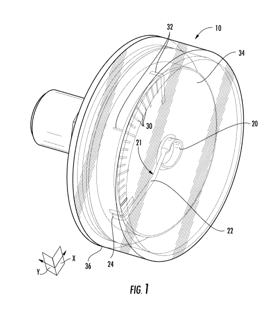
[0008] FIG. 1 is a side perspective view of a pressure gauge
according to
one embodiment.
[0009] FIG. 2 is an exploded view of the pressure gauge of FIG. 1.
[00010] FIG. 3 is a front plan view of the pressure gauge of FIG. 1, shown
assembled with a pressure cylinder.
[00011] FIG. 4 is a side perspective view of the pressure gauge of FIG. 1,
shown assembled with a pressure cylinder.
DETAILED DESCRIPTION OF THE DRAWINGS
[00012] The subject matter of embodiments of the present invention is
described here with specificity to meet statutory requirements, but this
2

CA 02884441 2015-03-09
WO 2014/043662
PCT/US2013/060033
description is not necessarily intended to limit the scope of the claims. The
claimed subject matter may be embodied in other ways, may include different
elements or steps, and may be used in conjunction with other existing or
future
technologies. This description should not be interpreted as implying any
particular order or arrangement among or between various steps or elements
except when the order of individual steps or arrangement of elements is
explicitly described.
[00013] Disclosed herein are pressure gauges for use with pressure
cylinders and the like, including but not limited to portable oxygen cylinders
used in aircraft or other suitable applications. As shown in Figure 1,
pressure
gauge 10 includes a pointer 21 having a body 22 that extends in a first
direction
and that bends at a distal tip 24 in a second direction that is generally
perpendicular to the first direction. The first direction is contained within
plane
X (Figure 1) and the second direction is contained within plane Y (Figure 1),
which is generally orthogonal to plane X.
[00014] A first set of pressure indicators 30 is included along the front
face 34 of the gauge 10. The first set of pressure indicators 30 is generally
contained within the same plane X as body 22. A second set of pressure
indicators 32 is included along the side 36 of the gauge and is generally
contained
within the same plane Y as the distal tip 24. In this way, the pressure
measurement indicated by pointer 21 can be viewed from both the front of the
gauge 10 and the side 36 of the gauge 10.
[00015] As shown in Figure 2, pointer 21 extends from a coil 20 that is
configured to expand when pressurized. As it expands, pointer 21 rotates so
that
it corresponds to the suitable indicator that identifies the pressure being
applied
to coil 20. In particular, body 22 corresponds to the suitable indicator from
the
first set of pressure indicators 30 and distal tip 24 corresponds to the
suitable
indicator from the second set of pressure indicators 32. Since distal tip 24
extends
approximately orthogonally from the body 22 of pointer 21, the body 22 of
pointer 21 points to the appropriate indicator 30 along the front surface 38
of case
3

CA 02884441 2015-03-09
WO 2014/043662
PCT/US2013/060033
28, while the distal tip 24 of pointer 21 points to the appropriate indicator
32
along the side surface 40 of the case 28. Side surface 40 is generally
contained
within plane Y and is generally orthogonal to front surface 38, which is
generally
contained within plane X. In this way, the pressure measurement can be read by
looking at the face of the gauge, as well as by looking at the side of the
gauge.
This eliminates constraints on where pressure cylinders can be stored and
used.
[00016] Indicators, such as indicators 30 and 32, may be printed on or
adhered directly to case 28, or may be included on a first dial 16 and a
second
dial 18 respectively that are then adhered or otherwise attached to case 28.
If
used, second dial 18 is configured to be positioned along the side surface 40
of
the case 28, while first dial 16 is configured to be positioned along the
front
surface 38 of the case 28. In some embodiments, first dial and second dial are

separate components, while in other embodiments they are one piece.
[00017] As shown in Figure 2, gauge 10 may include a fitting 14 for
attaching the gauge to a pressure cylinder, such as pressure cylinder 12 shown
in
Figures 3-4, by threading or otherwise. The pressure gauge 10 may also include
a
cover 26 that protects the internal parts of the gauge, including the coil 20,
the
pointer 21, and the first and second sets of pressure indicators 30, 32, and
prevents access to and/or tampering with the components of the gauge.
[00018] The foregoing is provided for purposes of illustrating,
explaining, and describing embodiments of the present invention. Further
modifications and adaptations to these embodiments will be apparent to those
skilled in the art and may be made without departing from the scope or spirit
of
the invention. Different arrangements of the components depicted in the
drawings or described above, as well as components and steps not shown or
described are possible. Similarly, some features and subcombinations are
useful
and may be employed without reference to other features and subcombinations.
[00019] Embodiments of the invention have been described for
illustrative and not restrictive purposes, and alternative embodiments will
become apparent to readers of this patent. Accordingly, the present invention
is
4

CA 02884441 2015-03-09
WO 2014/043662
PCT/US2013/060033
not limited to the embodiments described above or depicted in the drawings,
and
various embodiments and modifications can be made without departing from the
scope of the claims below. For example, although the various planes, surfaces,

and directions referred to herein are described as generally orthogonal to one
another, they are not so limited and may be oriented at any suitable angle
relative to one another. Similarly, the distal tip may extend from the body of
the
pointer at any suitable angle.
[00020] Moreover, although pressure gauge 10 is illustrated as a Bourdon
type pressure gauge, any suitable type of pressure gauge that has a
needle/pointer may include the at least two sets of pressure indicators
described
herein. Moreover, in some embodiments, the pressure gauge includes more than
two sets of indicators. Pressure gauge 10 is also not limited to use with
pressure
cylinders, but may be used in any suitable application where it is desirable
to
measure pressure and to read such measurements from various angles relative to
the gauge.
5

Representative Drawing
A single figure which represents the drawing illustrating the invention.
Administrative Status

For a clearer understanding of the status of the application/patent presented on this page, the site Disclaimer , as well as the definitions for Patent , Administrative Status , Maintenance Fee  and Payment History  should be consulted.

Administrative Status

Title Date
Forecasted Issue Date Unavailable
(86) PCT Filing Date 2013-09-17
(87) PCT Publication Date 2014-03-20
(85) National Entry 2015-03-09
Dead Application 2017-09-19

Abandonment History

Abandonment Date Reason Reinstatement Date
2016-09-19 FAILURE TO PAY APPLICATION MAINTENANCE FEE

Payment History

Fee Type Anniversary Year Due Date Amount Paid Paid Date
Registration of a document - section 124 $100.00 2015-03-09
Application Fee $400.00 2015-03-09
Maintenance Fee - Application - New Act 2 2015-09-17 $100.00 2015-03-09
Owners on Record

Note: Records showing the ownership history in alphabetical order.

Current Owners on Record
AVOX SYSTEMS, INC.
Past Owners on Record
None
Past Owners that do not appear in the "Owners on Record" listing will appear in other documentation within the application.
Documents

To view selected files, please enter reCAPTCHA code :


To view images, click a link in the Document Description column. To download the documents, select one or more checkboxes in the first column and then click the "Download Selected in PDF format (Zip Archive)" or the "Download Selected as Single PDF" button.

List of published and non-published patent-specific documents on the CPD .

If you have any difficulty accessing content, you can call the Client Service Centre at 1-866-997-1936 or send them an e-mail at CIPO Client Service Centre.


Document
Description 
Date
(yyyy-mm-dd) 
Number of pages   Size of Image (KB) 
Abstract 2015-03-09 2 84
Claims 2015-03-09 3 114
Drawings 2015-03-09 4 126
Description 2015-03-09 5 223
Representative Drawing 2015-03-09 1 40
Cover Page 2015-03-23 2 59
PCT 2015-03-09 12 416
Assignment 2015-03-09 8 320